Fibra é uma tecnologia de comunicação que os dispositivos com fios Ajax utilizam para transmitir alarmes e eventos. Os dispositivos Fibra fazem parte da linha de produtos Superior e são concebidos para os projetos de alto nível. Apenas os parceiros acreditados da Ajax Systems podem vender, instalar e administrar os produtos Superior. Para obter a acreditação, é necessário concluir com êxito um programa de formação especial da Ajax Academy.
Preparámos este artigo para ajudar os profissionais que trabalham com dispositivos com fios Ajax ou que planeiam fazê-lo. Inclui respostas a perguntas básicas sobre dispositivos com fios, sugestões para os instalar e configurar e ligações a materiais educativos úteis.
Todas as categorias de produtos Ajax são compatíveis: Proteção contra intrusão ( Superior e Baseline), Videovigilância, Segurança contra incêndio, ou Conforto e automatização. Isso oferece diversas possibilidades para a construção de sistemas com qualquer configuração.
Este manual será útil tanto para engenheiros de projeto como para instaladores ou engenheiros de colocação em funcionamento. Complementa os manuais de utilizador de cada dispositivo. Por isso, recomendamos que leia os manuais de utilizador dos dispositivos Fibra antes de ler este artigo.
Conceção do projeto
A conceção adequada de um projeto de sistema de segurança garante que os dispositivos do sistema são instalados e configurados corretamente. O projeto deve ter em conta muitos fatores. Estes incluem o número e os tipos de dispositivos na instalação, a sua localização exata e a altura de instalação, o comprimento das linhas Fibra, o tipo de cabo utilizado e outros parâmetros. Além disso, um projeto preciso pode ajudar a resolver problemas do sistema no futuro. Por exemplo, se um dos detetores falhar, será mais fácil encontrá-lo e substituí-lo por um semelhante.
Antes de criar um projeto, é necessário consultar o cliente. Descubra as suas necessidades e preocupações, como utilizam as instalações e o que esperam do sistema de segurança. Por exemplo, o cliente pode precisar apenas de proteção contra roubo ou também de um sistema de prevenção de inundações.
Além disso, antes de conceber um projeto de sistema de segurança, é necessário visitar o local, inspecioná-lo e analisar os projetos de sistemas de utilidade pública. O local pode ser diferente do plano, o que também é importante ter em conta. Além disso, ajudará a identificar fatores menos óbvios que podem afetar a realização do sistema de segurança. Por exemplo, a forma como os raios de sol incidem nas instalações ou onde os proprietários vão instalar um ar condicionado.
Análise do local
Na fase de análise, é necessário considerar todas as formas como os intrusos podem entrar na área protegida. Os dispositivos de segurança devem controlar todas as portas, janelas, portões, portas de vedação e outras entradas e saídas.
Se o local tiver janelas de telhado, também deve prestar atenção a elas. Um intruso pode entrar na sala através do teto.
É igualmente necessário considerar todas as fontes possíveis de alarmes nos locais e os seus tipos. Esta medida contribuirá para garantir a segurança global da instalação. Por exemplo, instale detetores de incêndio Ajax e pontos de chamada manuais para deteção precoce de incêndios, ou integre Button Jeweller e DoubleButton Jeweller nas caixas registadoras da loja para sinalizar um alarme.
As soluções de interior são igualmente tidas em conta na análise e na conceção do projeto. Por exemplo, um armário não deve bloquear a visão do detetor; uma lâmpada não deve iluminar a câmara fotográfica do detetor que suporta a verificação fotográfica; e numa divisão com lareira ou ar condicionado, é preferível instalar um detetor de movimentos com um sensor de micro-ondas adicional.
A distância mínima entre detetores de movimento com sensores de micro-ondas adicionais p. ex. Superior MotionProtect Plus G3 Fibra deve ser de, pelo menos, 7,87″. Caso contrário, pode diminuir a qualidade da deteção ou desencadear falsos alarmes devido à interferência das ondas dos sensores de micro-ondas da banda K.
Não se esqueça de verificar com o cliente se haverá animais de estimação no local. Isto afeta as definições, a localização e a altura de instalação do detetor de movimentos.
Verifique se a instalação possui objetos de particular importância, tais como pinturas caras, vasos, cofres, etc. Podem ser utilizados detetores separados para proteger estes objetos. Por exemplo, instalar Superior SeismoProtect G3 Fibra ou o Superior DoorProtect G3 Fibra no interior do cofre. O detetor ativará um alarme se alguém tentar arrombar o cofre.
Se for necessário ligar fechaduras elétricas, elementos de bloqueio adicionais ou outros dispositivos de terceiros que exijam controlo automático da potência, pode utilizar Superior MultiRelay Fibra ou Superior MultiTransmitter IO (4X4) Fibra.
Seleção de dispositivos
Com base nos resultados da análise, são selecionados os detetores e dispositivos que respondem eficazmente aos requisitos do cliente e protegem o local.
Ao selecionar os dispositivos, tenha em conta a sua zona de deteção. Isto é necessário para evitar ângulos mortos e falsos alarmes. Por exemplo, se instalar um íman grande do detetor de abertura à distância máxima (0,79″) do dispositivo, o detetor pode não responder à abertura de portas ou emitir falsos alarmes.
Para escolher os dispositivos corretos, é importante compreender como funciona o sistema, as diferenças entre detetores e qual o dispositivo mais adequado para cada situação. Para tal, leia o manual do utilizador de cada dispositivo que pretende utilizar no projeto.
Utilize o Superior LineProtect Fibra para proteger o hub e os dispositivos na linha contra curto-circuitos e sabotagem. O dispositivo pode ser instalado em qualquer ponto da linha Fibra. O módulo protege os dispositivos na linha instalada entre o Superior LineProtect Fibra e o hub, bem como o próprio hub. No entanto, o módulo não protege os dispositivos entre o Superior LineProtect Fibra e o último dispositivo na linha.
Se já existir um sistema com fios instalado no local, estes detetores podem ser integrados num sistema Ajax. É possível ligar dispositivos com fios de terceiros a um sistema Ajax utilizando módulos de integração.
Tanto a lógica do sistema como o hardware limitam o número máximo de dispositivos. A lógica do sistema inclui limitações ao número de dispositivos. As limitações da lógica do sistema podem ser encontradas no manual do utilizador da central de controlo nas nossas páginas da web de suporte e de comparação de hubs.
A parte de hardware inclui limitações de potência e de comprimento da linha Fibra. Se precisar de linhas mais longas do que 6,550 ft nas instalações do seu cliente ou se alguns dispositivos não tiverem energia do hub, utilize o Superior LineSupply Fibra. O módulo fornece uma fonte de alimentação adicional para os dispositivos Fibra ligados e aumenta o comprimento da linha para 6,550 ft a mais. Podem ser instalados até 10 módulos Superior LineSupply Fibra numa única linha Fibra. Também pode utilizar Superior LineSplit Fibra para prolongar ou dividir linhas.
A corrente máxima que o painel de controlo híbrido pode fornecer no total para todas as linhas Fibra depende do modelo do hub. Tenha em atenção que o consumo total de corrente dos dispositivos no sistema depende do tipo de cabo, do seu comprimento, do tipo de dispositivo ligado, do estado de ligação do condutor e de outros fatores. Por conseguinte, recomendamos que verifique o projeto com o nosso calculador online depois de selecionar os dispositivos. Mostra com exatidão se a capacidade do sistema de alimentação elétrica é suficiente para a configuração específica do dispositivo.
Topologias
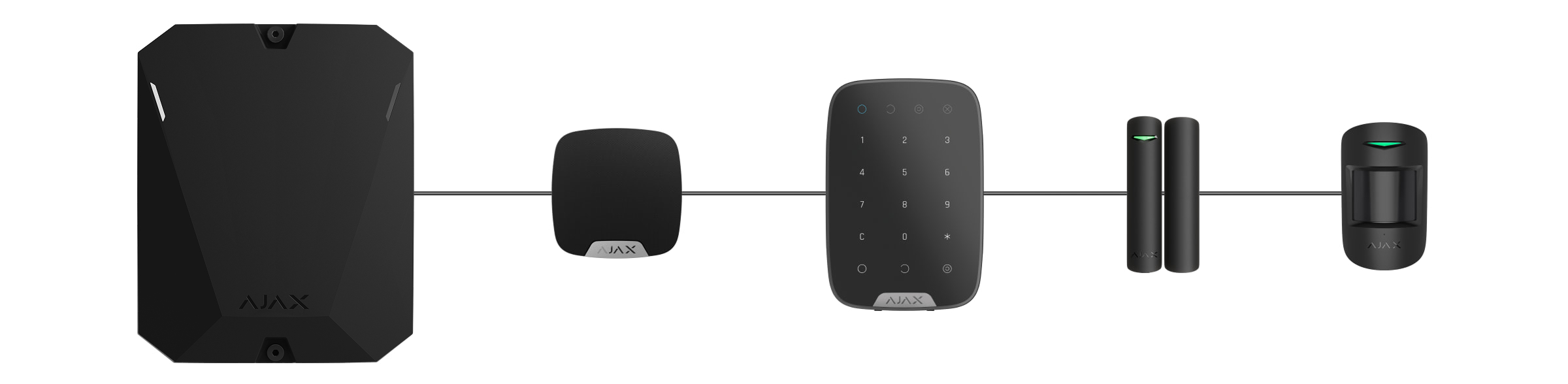
Fibra é um protocolo de transferência de dados para os dispositivos com fios Ajax. A nível físico, Fibra assemelha-se a uma ligação bus: os detetores são ligados à central por um cabo de quatro condutores. Atualmente, os sistemas Ajax suportam três topologias: Feixe (cablagem Radial), Anel e Árvore.
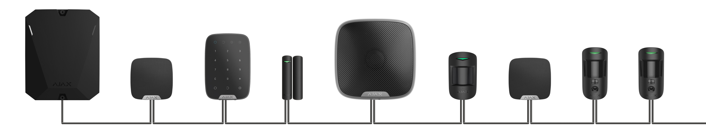
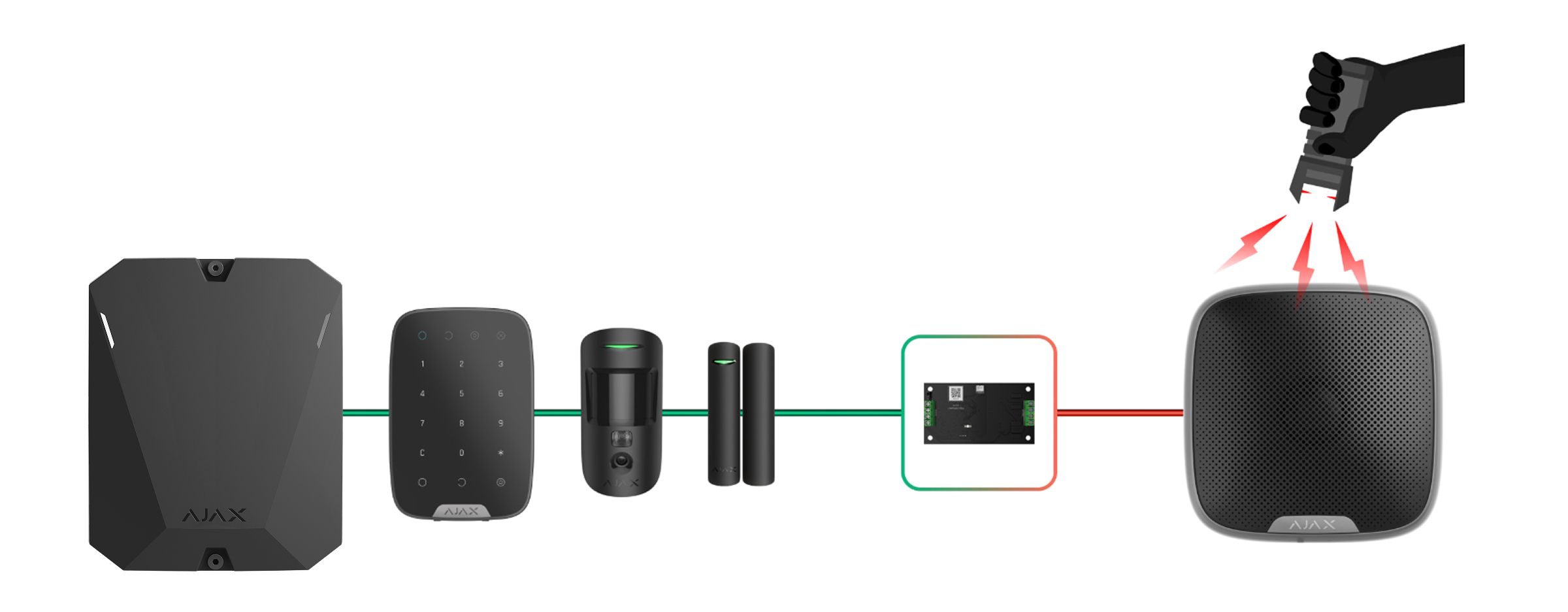
A ligação por Feixe (cablagem Radial) utiliza uma linha Fibra do hub. No caso de uma quebra de linha, apenas o segmento que permanece fisicamente conectado ao hub funcionará. Todos os dispositivos ligados após o ponto de interrupção perderão a ligação com o hub.
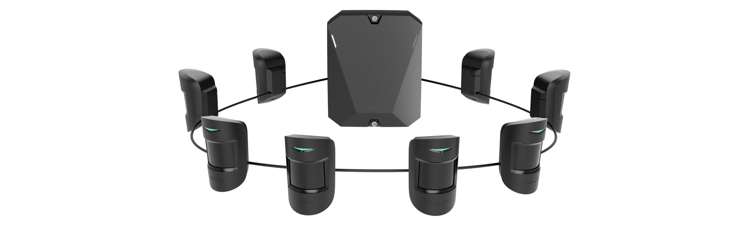
A ligação por Anel utiliza duas linhas Fibra do hub. No caso de uma rutura de anel num local, nenhum dispositivo será desativado: as duas linhas formadas continuarão a funcionar normalmente e a transmitir eventos para o hub. Os utilizadores e a empresa de segurança receberão uma notificação da quebra de linha.
| Feixe (Cablagem Radial) | Anel |
|
|
Os dispositivos são ligados à linha Fibra um por um, conforme demonstrado no diagrama. A ramificação de linhas e a topologia em Árvore só são permitidas quando é utilizado SuperiorLineSplit Fibra.
Superior LineSplit Fibra divide uma linha Fibra em quatro linhas. Cada linha de saída pode ter até 2000 m 6550 ft de comprimento quando ligada com o tipo de cabo recomendado. O módulo pode ser instalado em qualquer ponto da linha, incluindo após outro Superior LineSplit Fibra.
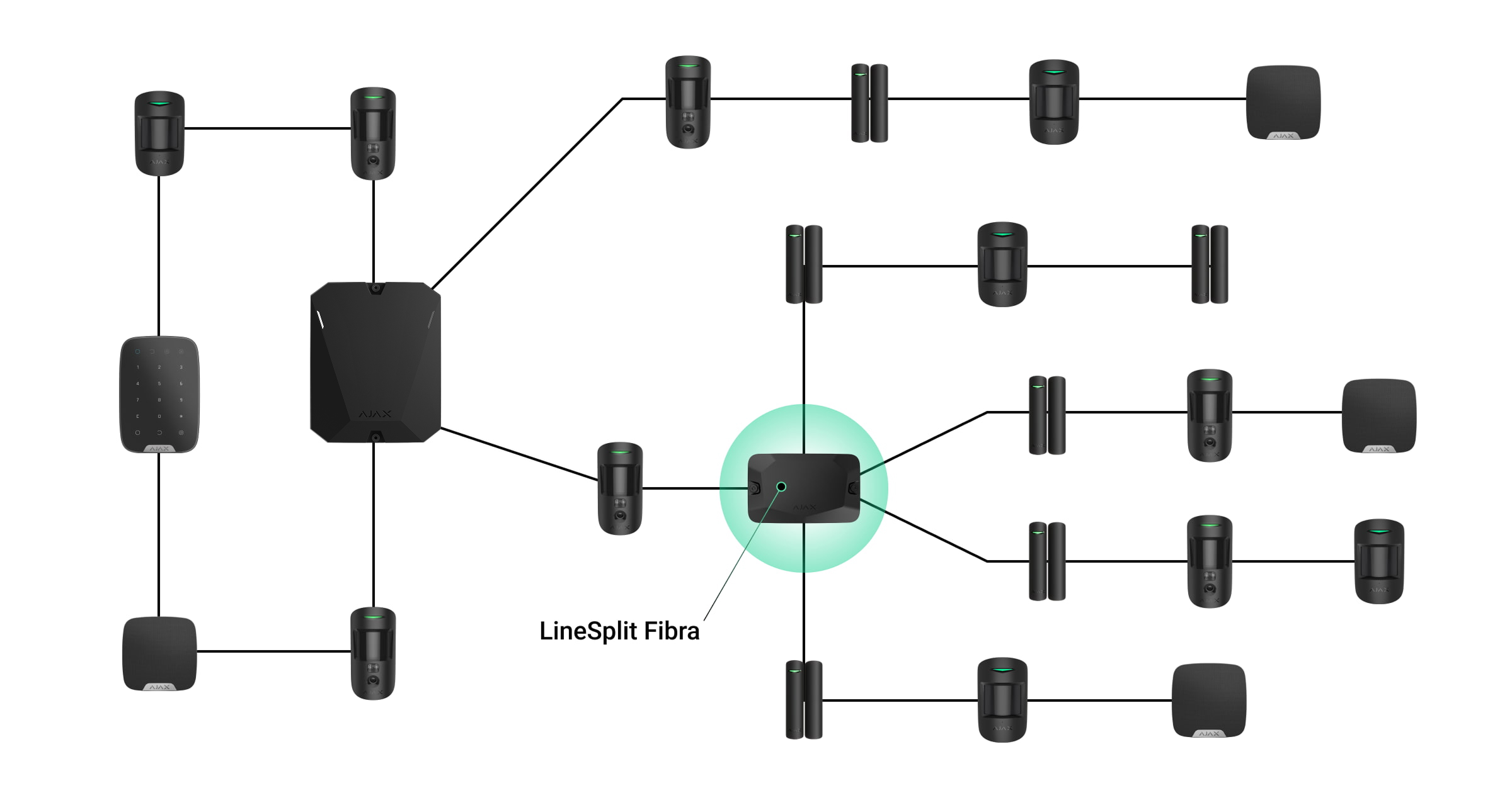
As linhas de saída criadas com o Superior LineSplit Fibra não suportam a topologia em Anel.
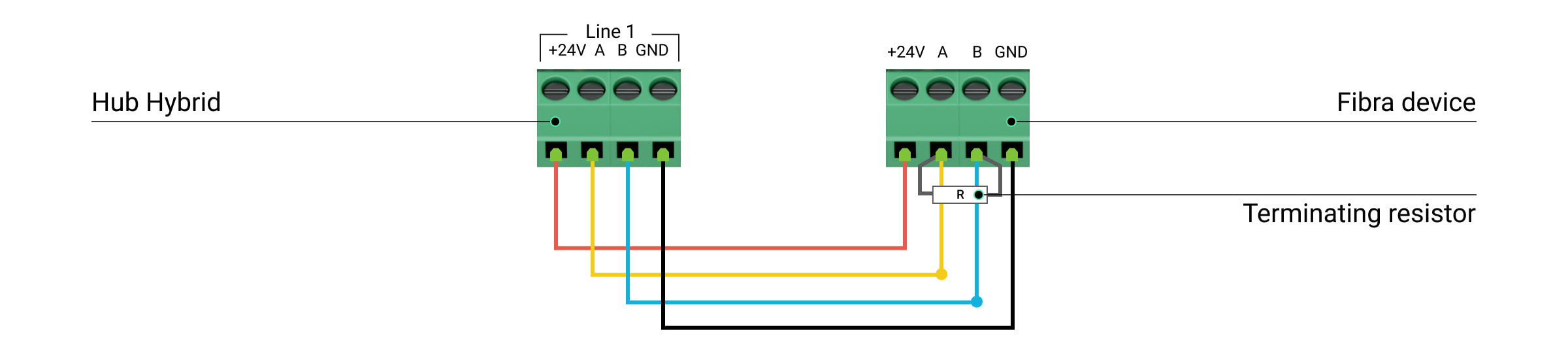
Quando é utilizada a topologia de Feixe, é necessária uma resistência de terminação de 120 Ω no final da linha. É ligado aos terminais de sinal do último detetor da linha. As resistências de terminação estão incluídas no conjunto completo dos painéis de controlo híbridos.
Todas as topologias de ligação de dispositivos podem ser utilizadas no mesmo hub. Por exemplo, pode utilizar duas ligações em Anel e quatro ligações de Feixe.
Se possível, recomendamos a ligação de dispositivos utilizando a topologia em Anel (hub — dispositivo — hub). Isto melhora a proteção contra sabotagem do sistema.
A tecnologia Fibra distingue-se pela sua versatilidade e eficiência energética. Podem ser conectados diferentes tipos de dispositivos a uma única linha Fibra. Por exemplo, pode ligar simultaneamente detetores de abertura, detetores de movimento com suporte de verificação fotográfica, sirenes e teclados à mesma linha.
Os dispositivos com fios da Fibra são energeticamente eficientes. Em média, os detetores consomem até 30–50 mW, o que é significativamente inferior ao desempenho médio dos detetores com fios existentes de outros fabricantes.
Comprimento e tipo do cabo
]Quando é utilizada a topologia de Feixe (cablagem Radial), o alcance máximo de uma ligação com fios é de 6550 ft. Se for utilizada a topologia em Anel, esse alcance é de 500 m 1600 ft. Isto proporciona flexibilidade na conceção do sistema. É possível passar um cabo de uma forma que não seja óbvia para um intruso, cobrindo diferentes dispositivos em todas as divisões. Desta forma, se um intruso tentar sabotar a linha, conseguirá desativar apenas alguns dispositivos, enquanto a proteção de toda a divisão permanecerá intacta.
Tenha em conta os locais de possíveis interferências de sinal. Se o cabo for encaminhado perto de motores, geradores, transformadores, linhas elétricas, relés de controlo e outras fontes de interferência eletromagnética, utilize um cabo de par entrançado nessas áreas.
Tipos de cabos recomendados:
- U/UTP cat.5 4×2×0,51 mm (24 AWG), condutor de cobre
- Cabo de sinal 4×0,22 mm², condutor de cobre
Verificação com um calculador
Para garantir que o projeto seja calculado corretamente e que o sistema funcione na prática, desenvolvemos dois calculadores: o calculador de alcance de comunicação de rádio e ao calculador de alimentação da Fibra.
Estas ferramentas são essenciais para a verificação do projeto. Os calculadores verificam a qualidade da comunicação via rádio entre o hub e os dispositivos do sistema, bem como o comprimento do cabo dos dispositivos com fios para a configuração selecionada.
Trabalhos preparatórios
Organização dos cabos
Ao preparar a instalação dos cabos, verifique as normas de segurança elétrica e contra incêndios da sua região e cumpra-as rigorosamente.
Para tornar os cabos invisíveis e inacessíveis aos intrusos, coloque-os no interior das paredes, do chão ou do teto. Este método de encaminhamento também garante uma maior durabilidade do cabo: o cabo estará exposto a menos fatores externos que afetam o desgaste natural do condutor e a camada isolante.
Regra geral, os cabos do sistema de segurança são colocados durante a fase de construção ou reparação ou quando a cablagem já está instalada no local.
Se não for possível colocar os cabos no interior das paredes, coloque-os de forma a ficarem suficientemente protegidos e escondidos de olhares indiscretos. Para este efeito, pode utilizar um suporte para cabos ou um tubo corrugado de proteção. É recomendável ocultar essas calhas ou tubos, por exemplo, atrás de móveis.
Recomendamos a utilização de tubos de proteção, condutas de cabos ou tubos ondulados para proteger os cabos, independentemente de serem ou não encaminhados para o interior da parede. Os cabos devem ser organizados com cuidado; não é permitido que fiquem soltos, emaranhados ou torcidos.
Passagem de cabos
Ao colocar cabos para um sistema de segurança, é necessário conhecer não só os requisitos e regras gerais para o trabalho de instalação elétrica, mas também as caraterísticas específicas de instalação de cada dispositivo. Estes incluem a altura de instalação, o método de montagem, a forma como o cabo é inserido na carcaça e outros parâmetros. Estes detalhes estão disponíveis nos manuais de utilizador dos dispositivos, que podem ser encontrados e visualizados na nossa página de suporte .
Tente evitar quaisquer desvios à conceção do sistema de segurança. Por exemplo, o aumento do comprimento do cabo pode levar à perda de ligação entre os detetores com fios e o hub. Ao mesmo tempo, a alteração da ordem de ligação dos dispositivos ou a sua substituição pode afetar a segurança do local.
Cubra as extremidades dos cabos com um saco de plástico ou uma película se o encaminhamento for efetuado durante a fase de reparação. Isto irá protegê-los da tinta ou do gesso. A entrada de tais materiais na extremidade do cabo pode afetar significativamente a qualidade do sinal entre o hub e os dispositivos do sistema.
Preparação dos cabos para conexão
Remova a camada isolante do cabo e descasque-o com um alicate de decapar especial para evitar danos no condutor. As extremidades dos fios que vão ser inseridos nos terminais do detetor devem ser estanhadas ou cravadas com uma manga. Isto garante uma conexão fiável e protege o condutor da oxidação.
Tamanhos de terminais de cabos recomendados: 0,75 a 1 mm².
As caraterísticas das carcaças de Superior DoorProtect Fibra, Superior DoorProtect Plus Fibra e Superior GlassProtect Fibra excluem a utilização de terminais de cabos isolados. Para ligar estes detetores, utilizar um terminal de virola não isolado com uma secção transversal de pelo menos 0,5 mm² e um comprimento até 0,24″.
Instalação e ligação do sistema
Instalação do painel de controlo e ligação dos cabos
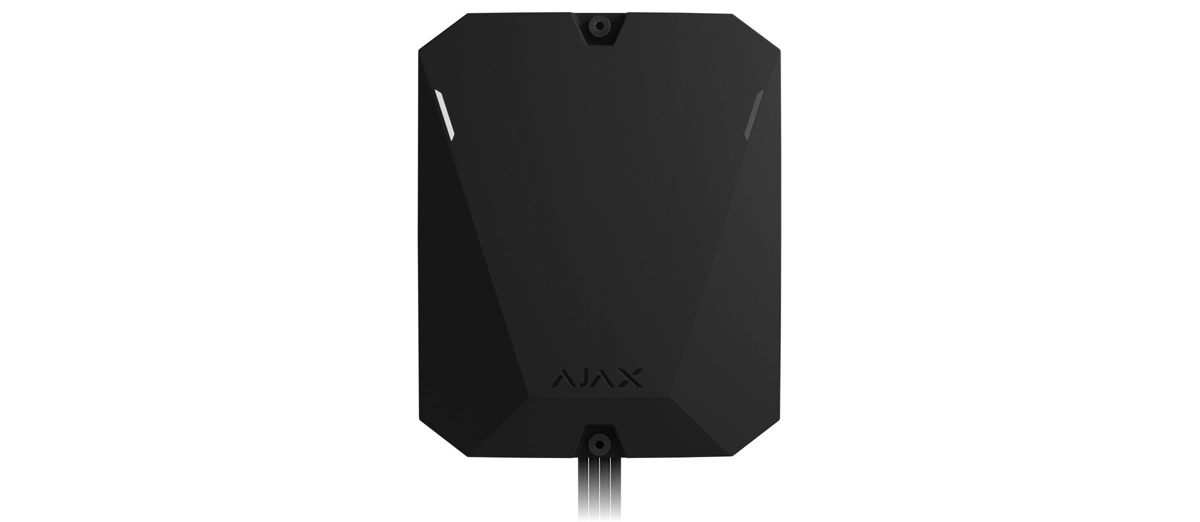
Os painéis de controlo híbridos estão disponíveis em duas versões: numa carcaça padrão (por exemplo, Superior Hub Hybrid (2G) e Superior Hub Hybrid (4G)e como uma placa sem carcaça (por exemplo, Superior Hub Hybrid (4G) (without casing)).
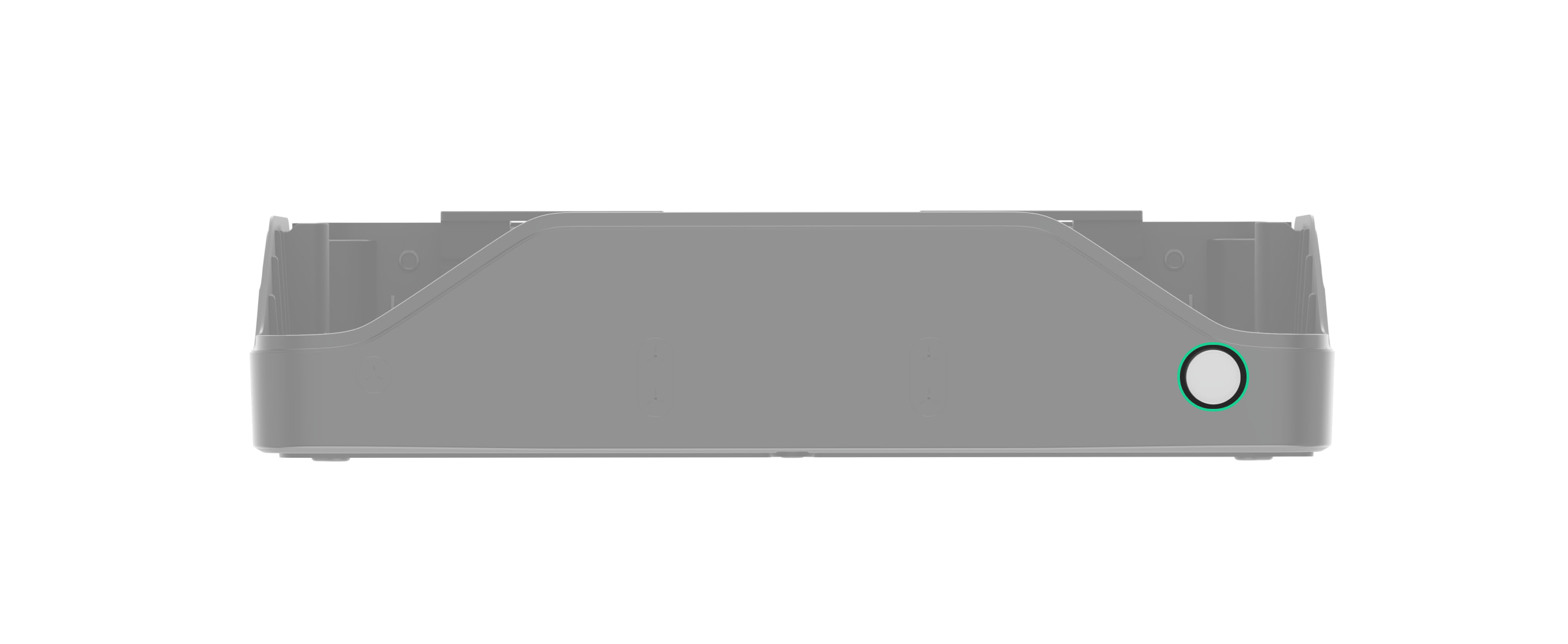
O Superior Hub Hybrid (2G) e o Superior Hub Hybrid (4G) só podem ser instalados na carcaça fornecida. É necessário para acionar os tampers situados em ambos os lados da placa. O lado frontal botão de tamper deteta tentativas de remoção da tampa da carcaça do painel de controlo. O botão de tamper na parte de trás avisa de tentativas de desprender a carcaça do painel de controlo da superfície.
O Superior Hub Hybrid (4G) (without casing) foi concebido para ser instalado na Case D (430), vendida separadamente. A placa do hub tem conectores para ligar a placa de tamper e a placa LED. A placa de tamper está incluída no conjunto completo da Case. Utilize o configurador de Case para determinar a colocação ideal dos dispositivos Fibra na carcaça. Apenas é possível instalar uma placa do painel de controlo numa única carcaça Case.
Para inserir os cabos na carcaça fornecida ou na Case, prepare previamente os furos. Antes de instalar o Superior Hub Hybrid (4G) (without casing), faça um furo para a guia de luz. Em seguida, instale a guia de luz e a placa de LED. Para instalar a placa Superior Hub Hybrid (4G) (without casing), fixe dois dispositivos Module Holder (type B) utilizando as calhas da Case.
A carcaça do hub e a Case estão tão bem preparados quanto possível para a instalação: todos os furos necessários para a montagem do painel de controlo já foram feitos. Os conjuntos completos de hub e Case incluem parafusos e buchas para uma instalação rápida.
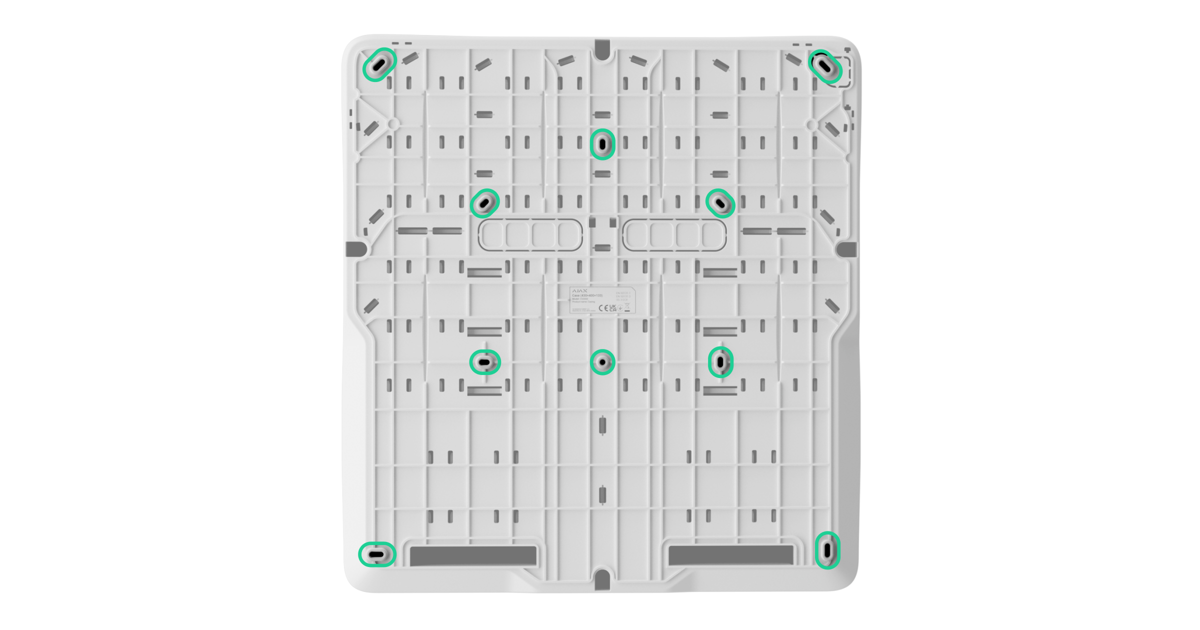
O hub é instalado numa superfície vertical escondida de olhares indiscretos. Para a montagem, utilize todos os pontos de fixação da carcaça. Certifique-se de que utiliza o ponto de fixação na parte perfurada da carcaça, que é necessário para acionar o tamper em caso de tentativas de desprender a carcaça da superfície.

Antes de conectar os cabos, desligue o hub, corte a alimentação e desligue a bateria de reserva. Ao ligar os cabos, certifique-se de que respeita a polaridade e a ordem de ligação dos fios. Fixe bem os condutores aos terminais. A carcaça e a Case do hub fornecem fixações para organizar e fixar os cabos com abraçadeiras de plástico.
Instalação dos dispositivos do sistema
Cada dispositivo tem um painel de montagem SmartBracket ou orifícios especiais na carcaça para montagem numa superfície.
Antes da instalação, retire o painel de montagem ou a parte da carcaça destinada à montagem do dispositivo. Prepare furos no painel de montagem ou numa parte da carcaça para passar os cabos. Retire cuidadosamente a parte perfurada ou perfurá-la, se permitido.
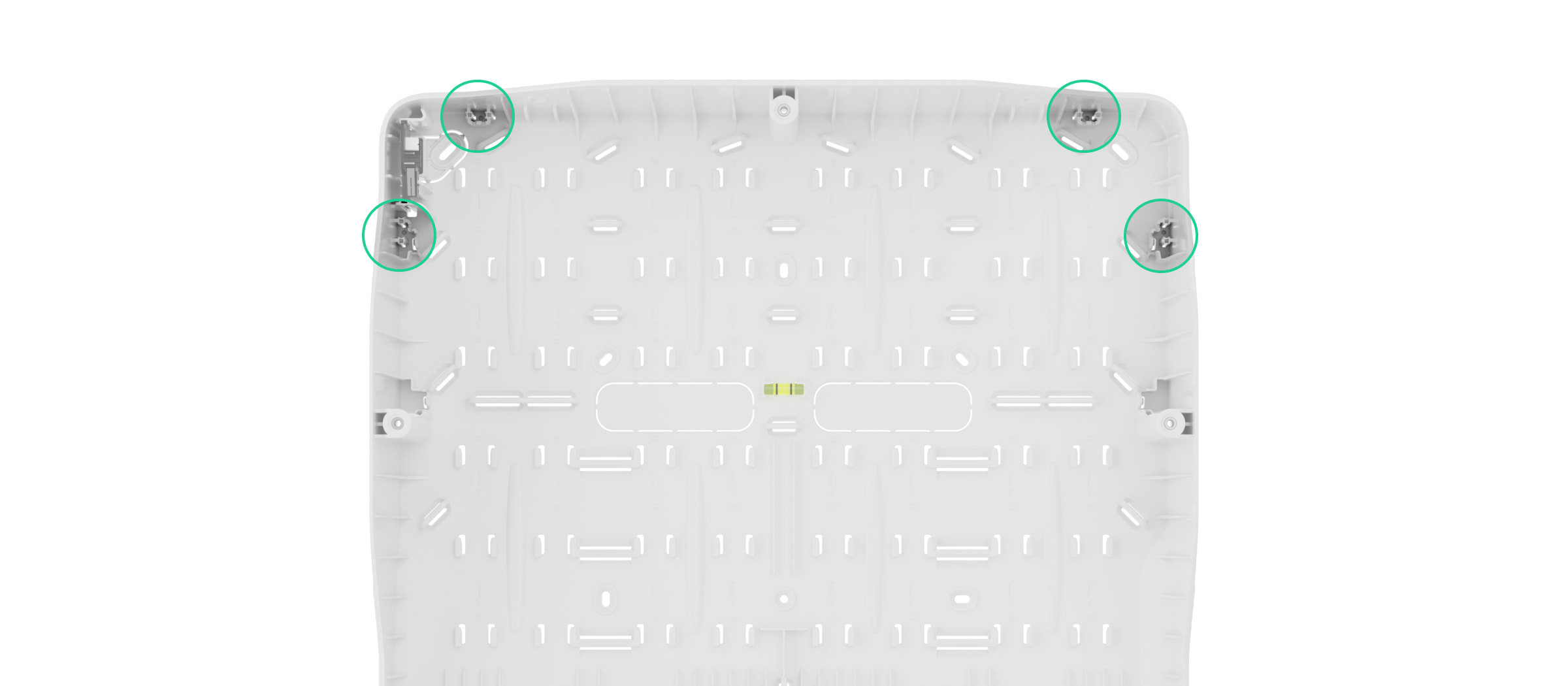
Locais para fazer furos para a passagem de cabos:
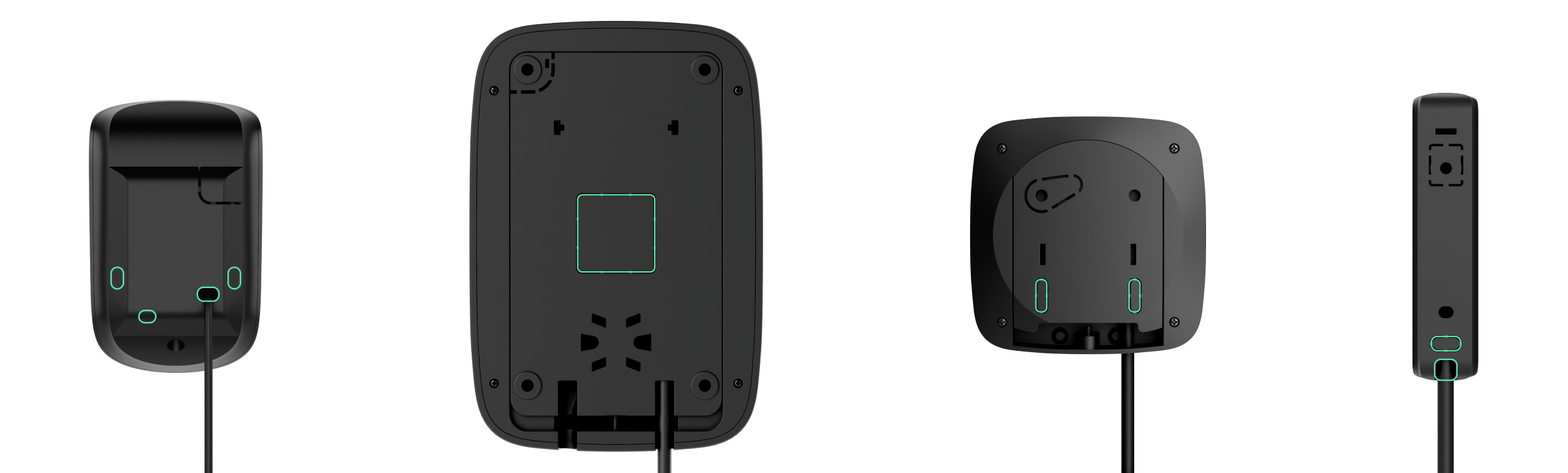
Certifique-se de que o local de instalação selecionado está em conformidade com o manual do utilizador. Todos os manuais podem ser encontrados na nossa página de suporte.
Antes da instalação, retire a placa com o bloco de terminais e passe o cabo pelo furo. Em seguida, fixe o painel de montagem ou parte da carcaça à superfície, utilizando todos os pontos de fixação, incluindo a parte perfurada. É necessário para acionar o tamper se for feita uma tentativa de desmantelamento do dispositivo. Utilize apenas os parafusos incluídos, uma vez que outros fixadores podem danificar ou deformar o painel de montagem ou a carcaça do dispositivo durante a instalação.
Depois de fixar o painel ou parte da carcaça à superfície, volte a instalar a placa de terminais em suportes especiais. Quando os cabos estiverem ligados aos terminais da placa, instale as restantes peças do dispositivo e fixe a carcaça com um parafuso incluído. Na parte inferior de cada dispositivo encontra-se um furo para parafusos.
Instalação na Case
Utilize Case quando precisar de instalar dispositivos Fibra sem carcaça ou aqueles que são compatíveis para instalação em Case. A lista completa de dispositivos compatíveis está disponível aqui. A Case é produzida em várias versões, e cada modelo tem um número diferente de slots, consoante a combinação de dispositivos. Utilize o configurador de Case para determinar a melhor colocação dos seus dispositivos Fibra na carcaça.
Para inserir os cabos na carcaça, prepare previamente os furos. Cada modelo de Case tem partes perfuradas e reentrâncias para fazer os furos de forma cómoda. Recomendamos a utilização de uma serra de furo para plástico, Ø16 mm, Ø20 mm, Ø32 mm, Ø40 mm ou Ø63 mm, consoante a versão da Case.
Para uma organização cómoda dos cabos, utilize fixadores de carcaça para fixar cabos e canais. Depois de passar os cabos, fixe a Case na superfície vertical com os parafusos incluídos, utilizando todos os pontos de fixação. Um deles está localizado na parte perfurada por cima de tamper e é necessário para acionar o tamper se alguém tentar retirar a carcaça. A Case tem o nível de bolha de ar para que possa verificar o ângulo de inclinação do suporte durante a instalação.
A Case possui fechos ou calhas de plástico para fixar os dispositivos Fibra, consoante o modelo da caixa. Quando todos os dispositivos estiverem instalados e os cabos encaminhados, conecte uma placa de tamper para os proteger de sabotagem.
Conexão de dispositivos Fibra
Os dispositivos são ligados à linha Fibra um por um, conforme demonstrado no diagrama. A ramificação de linha só é permitida quando se utiliza Superior LineSplit Fibra ou Superior LineSupply Fibra.
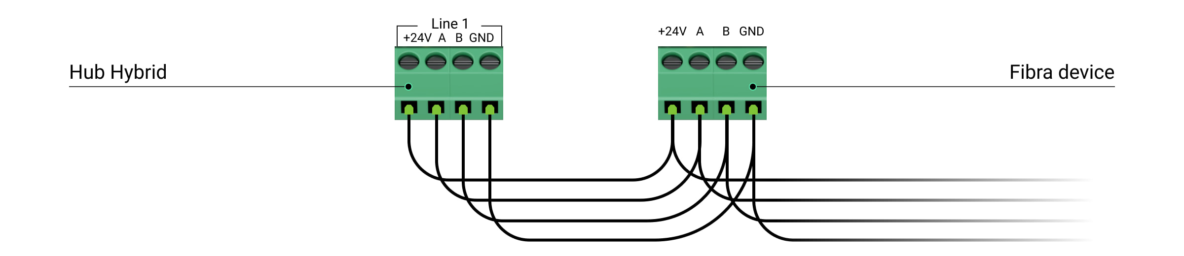
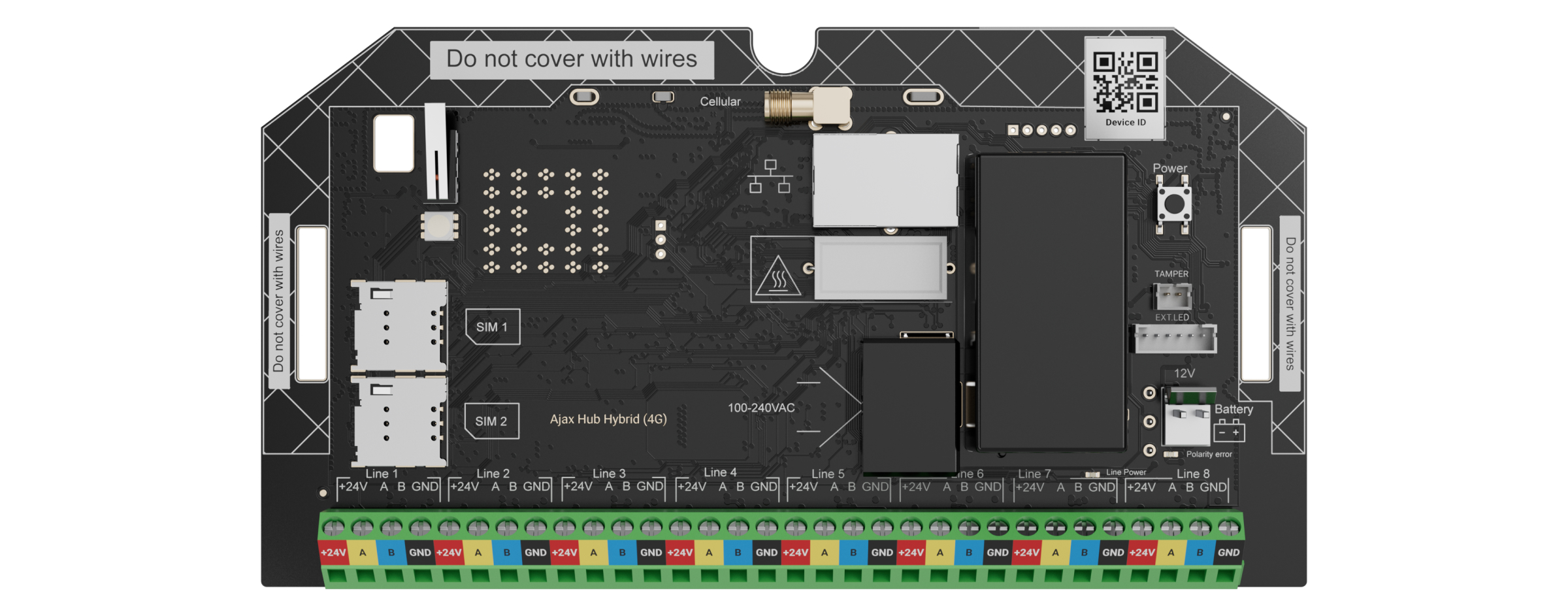
Existem quatro terminais na placa do dispositivo:
+24V — alimentação
A, B — terminais de sinal
GND — terra
Os detetores Superior DoorProtect Fibra, Superior DoorProtect G3 Fibra, Superior DoorProtect Plus Fibra e Superior GlassProtect Fibra têm terminais adicionais para ligar dispositivos de terceiros com um tipo de contacto NC (normalmente fechado).
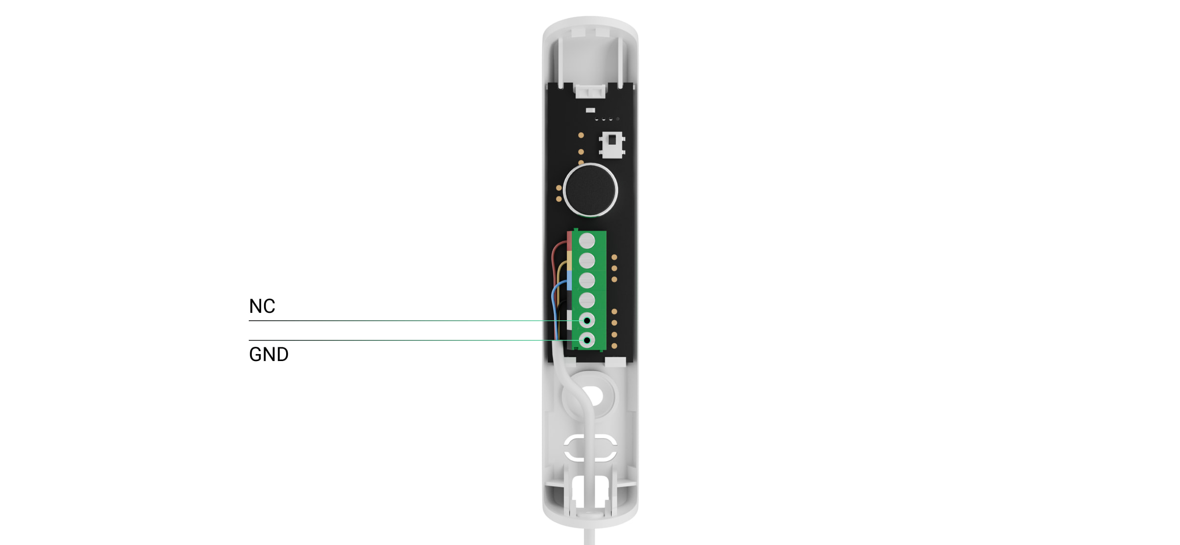
NC — Terminal para ligação de um contacto externo/detetor de persiana (para Superior DoorProtect Plus Fibra)
GND — terra
A Superior HomeSiren Fibra dispõe de um terminal adicional para a ligação de um LED externo.

Ligue os dispositivos apenas às linhas desenergizadas do hub. Pode desligar a fonte de alimentação das linhas nas definições do painel de controlo híbrido. Certifique-se de que respeita a polaridade e a ordem de ligação dos fios. Ligue o cabo aos terminais e fixá-lo com braçadeiras de cabos utilizando os fixadores no interior do painel de montagem.
Configuração do sistema
Adicionar o hub ao espaço
Só é possível adicionar e configurar painéis de controlo híbridos através da app Ajax PRO. Antes de adicionar o hub, crie uma conta na app.
Conecte um cabo Ethernet e/ou cartões SIM, uma fonte de alimentação externa e uma bateria de reserva ao hub.
Ligue o hub e aguarde até que o indicador LED se acenda a verde ou branco, indicando a ligação com o Ajax Cloud. Leia mais sobre a indicação LED no manual do utilizador.
Preste atenção ao conjunto completo do hub para preparar antecipadamente os componentes necessários para a sua conexão.
| Incluído no conjunto completo | Não incluído no conjunto completo |
|
|
Na app, adicione o hub ao espaço digitalizando o código QR do dispositivo ou introduzindo o seu ID manualmente. O código QR com um ID está localizado na placa do hub, na parte de trás da carcaça e na embalagem.
¹ Incluído no conjunto completo do Superior Hub Hybrid (4G) (without casing).
² Incluído no conjunto completo da Case.
Definições do hub
Os manuais de utilizador dos painéis de controlo híbridos contêm uma descrição completa de todas as definições. Esta secção abordará pontos importantes, funcionalidades úteis e definições não óbvias.
Canais de comunicação
Recomendamos a ligação do hub através de todos os canais de comunicação em simultâneo: Ethernet e dois cartões SIM. O sistema estará protegido mesmo que um dos operadores de telemóveis sofra interrupções. A app fornece o estado da ligação do canal de comunicação em qualquer altura.
Ao ligar cartões SIM, defina o APN e outras definições de rede recomendadas pelo operador de telemóvel. Se a rede utilizar endereços IP estáticos, estes também devem ser especificados nas definições de Ethernet.
Grupos
Os dispositivos Fibra com fios podem ser combinados num grupo de segurança com dispositivos sem fios, independentemente da sua ligação física e localização. Ative e configure o Modo de grupo se o projeto o exigir. O número máximo de grupos de segurança para painéis de controlo híbridos é 9.
Calendário de segurança
Num sistema Ajax, é possível definir um calendário de segurança para um local. Os cenários permitem alterar o modo de segurança para grupos de segurança individuais ou para todo o sistema, bem como definir o Modo noturno a uma hora específica.
Configuração do sistema de acordo com as normas
Se o seu projeto exigir o cumprimento de uma determinada norma, tenha-a em conta na instalação e configuração do sistema. Pode obter mais informações sobre a lista de definições necessárias nos nossos materiais:
Definições da bateria
Estas definições permitem aumentar a duração da bateria.
A funcionalidade Maximizar a duração da bateria prolonga a vida útil da bateria de reserva do hub. Quando a definição está ativada, o carregamento pára a 100% e recomeça a 80% da carga da bateria.
Para garantir até 200 horas de duração da bateria, ative a funcionalidade Poupar carga da bateria de reserva do hub¹ e altere o intervalo de consulta do servidor e o tempo durante o qual o hub permanece ligado ao Ajax Cloud após qualquer evento no sistema. A duração da bateria depende da capacidade da bateria de reserva, da configuração do sistema e do número de dispositivos adicionados ao hub.
¹ Quando o modo de Poupança de bateria está ativado, o sistema não cumpre a norma EN 50131 (Grade 3).
Adição de dispositivos ao sistema
Estão disponíveis duas formas de adicionar dispositivos:
- Manualmente. Este é o procedimento normal para adicionar um dispositivo. Para adicionar um dispositivo, é necessário digitalizar o respetivo código QR ou introduzir a ID manualmente. Este método é adequado para adicionar dispositivos sem fios e um pequeno número de dispositivos com fios e é conveniente para substituir um dispositivo avariado durante a manutenção.
- Automaticamente. Este método envolve a adição de dispositivos com fios utilizando a funcionalidade de leitura de linha. O método é adequado para adicionar um grande número de dispositivos Fibra ligados às linhas. Esta caraterística ajudará a reduzir o tempo necessário para configurar o sistema. Quando a leitura estiver concluído, a lista de dispositivos Fibra ligados é ordenada por linhas Fibra. Para identificar um dispositivo, o respetivo LED acende-se quando recebe um comando da app. Também está disponível uma forma alternativa de identificar dispositivos. Quando ocorre um alarme, o dispositivo é apresentado no topo da lista. Pode iniciar a leitura de linhas no menu para adicionar dispositivos e nas definições do hub.
Para mais informações sobre a leitura automática de linhas, consulte os manuais de cada dispositivo Fibra na nossa página de assistência.
Definições do dispositivo
Pode encontrar uma descrição completa de todas as definições para cada dispositivo na nossapágina de assistência . Esta secção abordará pontos importantes, funcionalidades úteis e definições não óbvias que são por vezes ignoradas.
Atraso ao entrar/sair
Atraso à entrada/saída é o tempo que o utilizador tem para alterar o modo de segurança do sistema depois de entrar ou sair das instalações.
É definido separadamente nas definições de cada detetor. As sirenes Ajax podem notificar a contagem decrescente do atraso com som. Esta função é ativada adicionalmente nos ajustes da sirene.
Modo Noturno
Modo Noturno é um modo de segurança em que apenas alguns detetores são ativados.
Modo Noturno só funciona com detetores de abertura, de quebra de vidro e de movimento. O Modo Noturno está desativado por predefinição e é configurado nas definições de cada detetor.
Resposta da sirene aos alarmes
Esta definição ativa as sirenes quando o detetor é acionado. É configurado separadamente para cada detetor. A sirene toca com o volume e a duração do sinal de alarme definidos nas definições da sirene.
Chime
Quando a função Chime (notificações de abertura de portas) está ativada, as sirenes emitem um som especial para indicar que os detetores de abertura são acionados quando o sistema é desarmado. A funcionalidade é utilizada, por exemplo, em lojas, para notificar os empregados de que alguém entrou no edifício.
A configuração da notificação é efetuada em duas fases: configuração das sirenes e configuração dos detetores de abertura. Nas definições dos detetores de abertura, a própria função é ativada. Nas definições da sirene, é necessário ativar a função e selecionar o volume e o som do alerta.
Códigos de acesso ao teclado
Os códigos de acesso são utilizados para gerir os modos de segurança utilizando os teclados Ajax. Um código de acesso e um código de coação podem ser gerais ou pessoais. Os códigos gerais são definidos nas definições do teclado, enquanto os códigos pessoais são definidos nas definições do hub diretamente pelo utilizador a partir da sua conta pessoal.
Sensibilidade do detetor de movimento
A funcionalidade é configurada para cada detetor separadamente com base nas especificidades do local, como a presença de animais de estimação, uma lareira ou outras possíveis interferências térmicas. Para os detetores de movimento exteriores, a distância de deteção também é ajustada através do cursor na parte de trás da carcaça.
Cenários de automatização
O sistema Ajax oferece a possibilidade de configurar dispositivos de automatização e Ajax WaterStop Jeweller em resposta a um alarme, alteração do modo armado, programação ou temperatura. Por exemplo, pode configurar a iluminação da rua para se ligar de acordo com uma programação, premindo Button Jeweller no modo de controlo ou em caso de alarme dos detetores de movimento instalados no perímetro. Além disso, o utilizador pode controlar dispositivos de automatização a partir de KeyPad TouchScreen Jeweller, Superior KeyPad TouchScreen Fibra, KeyPad Outdoor Jeweller, e Superior KeyPad Outdoor Fibra. Os cenários são criados e editados nas definições dos dispositivos de automatização, hubs ou teclados.
Os detetores da série MotionCam que suportam a função Foto por cenário podem tirar fotografias em caso de alarmes de outros dispositivos Ajax ou numa hora especificada. Um utilizador com direitos de administrador pode criar e ajustar esse cenário nas definições do detetor, bem como especificar quando é possível tirar fotografias nas definições de Privacidade do espaço.
Teste do sistema
Um sistema Ajax oferece os seguintes testes para o ajudar a escolher o local certo para instalar dispositivos e verificar a sua funcionalidade:
- Teste de intensidade de sinal do Jeweller
- Teste de intensidade de sinal do Wings
- Teste de intensidade do sinal Fibra
- Teste da zona de deteção
- Ensaio de atenuação
- Teste de alimentação das linhas
- Teste da área de cobertura
- Teste de volume
- Calibração do sensor de mascaramento
- Auto-teste
Os testes de intensidade de sinal Jeweller, Wings e Fibra determinam a intensidade e a estabilidade do sinal no local pretendido para o dispositivo.
O teste da zona de deteção ajuda a determinar a distância a que o dispositivo irá detetar alarmes no local de instalação atual.
O teste de atenuação do sinal permite-lhe reduzir ou aumentar artificialmente a potência do transmissor de rádio. O teste simula alterações no ambiente interior para verificar a estabilidade da ligação entre o dispositivo e o hub.
O teste das linhas de alimentação simula o consumo máximo possível de energia dos dispositivos Fibra com fios: os detetores disparam os alarmes, os teclados são ativados e as sirenes são ligadas. Se o sistema passar no teste, todos os seus dispositivos com fios terão alimentação suficiente em qualquer situação.
A calibração do sensor de mascaramento é importante para o funcionamento correto do Superior DoorProtect G3 Fibra ou dos detetores de movimento Ajax. Se o detetor estiver calibrado, detetará instantaneamente as tentativas de utilização de ímanes fraudulentos. A calibração do sensor de mascaramento do detetor de movimento é importante para garantir que o dispositivo funciona corretamente e pode detetar instantaneamente tentativas de bloquear o campo de visão dos seus sensores. Calibrar o sensor imediatamente após adicionar o dispositivo ao sistema ou alterar o seu local de instalação.
Os auto-testes ajudam a verificar se os sensores incorporados no dispositivo funcionam corretamente. Utilize-os depois de instalar os detetores das séries Superior DoorProtect G3 Fibra, Superior SeismoProtect G3 Fibra ou FireProtect. O teste da área de cobertura dos detetores FireProtect 2 verifica se todos os detetores de incêndio continuam a responder a um alarme em caso de perda da ligação com o hub. O teste envolve detetores que suportam a função de alarme de incêndio interligado de recurso.
O teste de volume da sirene permite verificar o seu nível de volume atual e selecionar o nível ideal para a instalação.
Após a instalação
Formação para clientes
Para utilizar o sistema, os utilizadores têm de descarregar a app Ajax Security System e criar uma conta. Quando uma conta é criada, um instalador adiciona todos os utilizadores ao hub e ajuda-os a configurar notificações e códigos de acesso. Os códigos são configurados se o sistema incluir teclados.
O instalador deve dar instruções ao cliente sobre a forma de gerir o sistema e explicar brevemente a lógica do funcionamento em Modo de grupo e em Modo noturno, caso sejam utilizados. Se existirem cenários no sistema, o instalador deve explicar o seu funcionamento.
Além disso, o instalador deve fornecer aos clientes as informações de contacto para o caso de terem alguma dúvida sobre o sistema. Os clientes também devem ter em conta que podem contactar a equipa de assistência da Ajax 24/7, para qualquer questão relacionada com o funcionamento do sistema, dispositivos e apps.
Contactos do Suporte Técnico Ajax
Manutenção
Verifique regularmente o funcionamento do sistema. A frequência ideal das verificações é regulada pelas leis e regulamentos do estado onde o sistema está instalado. Verifique a carga da bateria dos dispositivos sem fios e substitua as baterias, se necessário. Verifique se os fios estão corretamente ligados aos terminais. Faça testes de funcionalidade. As verificações regulares são importantes e ajudarão a detetar e a evitar avarias.
Apoio ao cliente
Para garantir que o sistema cumpre os requisitos do cliente e se mantém preparado para o futuro, lançamos regularmente novos dispositivos, atualizações de apps e novas versões de firmware para hubs e repetidores.
Os clientes ficam sempre satisfeitos por obterem novas funcionalidades através de atualizações gratuitas de firmware e de apps. Um instalador, por sua vez, pode oferecer-lhes novos dispositivos e um serviço à distância de qualidade.
Por conseguinte, aconselhamos os instaladores a comunicar com os clientes após a instalação do sistema e a informá-los de quaisquer funcionalidades adicionais e de novas versões de dispositivos. Enviamos regularmente e-mails aos parceiros e a todos os utilizadores de apps PRO sobre os lançamentos de atualizações. As notícias da empresa também estão disponíveis no Blogue.