LineSupply (45 W) Fibra

Module for additional power supply of Fibra devices

FAQ

The difference between the modules is the number of output lines for connecting wired devices and the output power.

LineSupply (45 W) Fibra has one output line and up to 45 W of the output power, while LineSupply (75 W) Fibra has two lines and up to 75 W power at the outputs.

The module’s output power is distributed between connected devices and the backup battery.

Copied

The module’s output power is distributed between connected devices and the backup battery.

For LineSupply (45 W) Fibra, the distribution is 30 W for devices and 15 W for the backup battery. For LineSupply (75 W) Fibra, it is 30 W for each of two output lines and 15 W for battery charging.

Copied

The maximum number of devices that can be connected to the module is determined by the hub (100 devices for Hub Hybrid) and the LineSupply Fibra output power. So before installing wired devices, we recommend checking the system configuration with a Fibra power supply calculator and performing a lines power supply test after installation.

Copied

Use a 12 V⎓ battery with a capacity from 7 to 18 Ah.

For batteries of this form factor, there are special holders in Case C (260) or Case D (430). Also, Case D (430) is additionally supplied with the holding stripe for the battery.

Copied

To install LineSupply Fibra, use Case C (260) or Case D (430), which are sold separately. You can mount one LineSupply Fibra in Case C (260) and two modules or other devices in Case D (430).

Each Case is equipped with mounts for modules, wire channels, and a tamper that can be connected to LineSupply.

Copied

Tamper board is a single board with a tamper button. The button contacts change a state when you try to open the casing lid or detach it from the surface. An Ajax hub receives a notification about the tamper triggering of the device. The hub activates the sirens added to the system, triggers scenarios, and notifies users and the security company.

Case has the tamper board. It’s connected to the Ajax device with a loop in the complete set.

Copied

The identifier (ID) is the serial number of the device. It is located under the QR code on the body, board, and packaging of the device.

ID at the bottom of the box

ID under the lid

The ID can also be found in the device states in the Ajax app.

  1. Sign in to the Ajax app.
  2. Select the required hub from the list if you have several of them or if you are using a PRO app.
  3. Go to the Devices menu.
  4. Select a device from the list. Device ID information is located at the bottom of the status screen.
Copied

In the states of each Fibra device, you can see its loop (zone) number as well as number of the line to which it is connected. When using the Ring topology, you can see to which ring the device is connected.

If the device is added to the hub, for example, using LineSupply (75 W) Fibra, you can see the module name and the output line number in the states.

Copied

The lines power test shows which devices and on which Fibra lines may have insufficient power supply.

If the power supply is insufficient, we cannot guarantee the stable operation of the security system.

Before installing wired devices, we recommend calculating the line length using an online calculator.

If a certain device is not getting enough power supply, you can:

  • Add devices to the hub through the LineSupply Fibra module.
  • Connect devices that are not powered enough to another Fibra line.
  • Reduce the number of devices on the Fibra line that is not powered enough.
  • Replace high-power consuming devices with lower-power devices if facility configuration allows.

After any change in the device configuration at the facility, we recommend re-testing the lines power supply.

Copied

When installing Fibra devices, be sure to observe the polarity and order of the wires connected.

Copied

When installing devices near power cables, we recommend using a shielded cable to lay the Fibra wired line.

Copied

Fibra devices work on 24V⎓ voltage.

The minimum allowable voltage for Fibra devices to operate is 8 V⎓. Such a voltage may be at the end of a line to which many devices are connected.

If the voltage on a device is below 8V⎓, a fault counter will appear on that device, and the Voltage field in the device States will turn to red color.

Thus, we recommend that you perform a Lines Power Test after installing the devices to ensure that they work correctly.

Copied

You can install outdoors only the StreetSiren Fibra and StreetSiren DoubleDeck Fibra sirens.

All remaining Fibra devices are designed for indoor installation. Outdoor installation may cause malfunctions and false alarms.

If you need to connect third-party wired outdoor detectors to the Ajax system, use the MultiTransmitter Fibra or Transmitter Fibra integration modules.

Detailed installation guidelines for each Fibra device are available in the User Manual for that device.

Copied

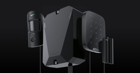
Ajax security system provides several tests to check the operation of wired devices.

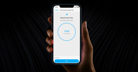
Fibra Signal Strength Test checks the device signal strength and stability at the intended installation location.

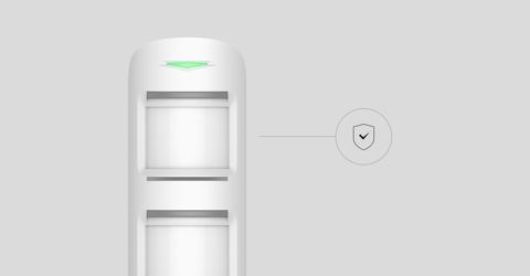
Detection Zone Test checks how the device responds to alarms (the test is only available for Ajax security detectors).

Volume Level Test — checks the siren volume sound at the intended installation location (the test is only available for Ajax sirens).

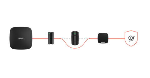
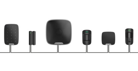
Lines Power Test simulates the maximum possible power consumption of the system: detectors generate alarms, keypads are activated, sirens are turned on. If the system successfully passed the test, then all its wired devices will have enough power supply in any situation.

During the lines power test, connected wired sirens are activated.

We recommend that you perform all security system tests after installing the devices to ensure that they work correctly.

Copied

Fibra devices are connected to the hub using Beam (Radial wiring), Ring, and Tree topologies.

As depicted in the diagram, wired devices should be connected to the Fibra line sequentially, one after the other, without any branching.

Line branching and the Tree topology are only allowed when using LineSplit Fibra.

The Ring topology is also available. If the line breaks, the devices will still be connected to the hub via the Beam (Radial wiring) connection, continuing to transmit events and alarms to the hub.

We recommend connecting devices using the Ring topology if possible. This improves the sabotage protection of the line.

Keep in mind, the output lines created when using LineSplit Fibra or LineProtect Fibra don’t support the Ring topology.

Learn more

Copied

The maximum length of a wired Fibra line is 2,000 meters.

The appropriate wired line length depends on the number and type of connected devices and the type of used cable.

Therefore, before installing wired devices, we recommend calculating the line length using an online calculator.

And after installing the devices, perform a Fibra Signal Strength Test and a Lines Power Test to make sure the system is working correctly.

Copied

Fibra devices are connected using a 4-wire cable.

We recommend using the following types of conductors:

  • U/UTP cat.5 twisted pair (4 × 2 × 0.51).
  • ALARM signal cable (4 × 0.22).
Copied

By default, the hub is set to a hub–detector ping interval of 36 seconds and 30 undeliverable data packets to consider the device lost. With these settings, the hub will detect the loss of the detector in 18 minutes.

To reduce this time, go to the hub settings in the Jeweller section and change the settings. The minimum time for detecting loss of connection with the device is 36 seconds (3 polls of 12 seconds each).

The time before raising the alarm by the communication loss between hub and device is calculated with the following formula:

Detector Ping Interval × Number of missed pings to determine connection failure

Note that with the minimum ping interval, short-term interference can lead to loss of connection with the device. Therefore, set the minimum values only if it is critically important to promptly inform about events in the system.

Copied

The loop (zone) number is required to describe all devices connected to the hub when adding a protected facility to the security company monitoring station.

The number is assigned when adding a device to the hub. The first added device has the first loop (zone) number. After removing the device from the system, its number becomes available. This number can be assigned to the next device to be added to the system.

The loop (zone) number is available in the states of each device in the Ajax app:

Copied

The firmware version can be found in the device states in the Ajax app.

  1. Sign in to the Ajax app.
  2. Select the required hub from the list if you have several of them or if you are using a PRO app.
  3. Go to the Devices menu.
  4. Select a device from the list. The firmware version information is located on the status screen at the bottom.
Copied

Go to the Devices tab , select the device you want to check.

ajax security system application
Copied

Featured articles

How to disable device events once for a time the armed mode is active

What is Fibra Signal Strength Test

Tips for installing and configuring wired Fibra devices

Spelling error report

The following text will be sent to our editors: