Superior LineSupply Fibra is a module for the additional power supply of devices on the Fibra line. The module is available in two versions: Superior LineSupply (45 W) Fibra with an output power of up to 45 W, and Superior LineSupply (75 W) Fibra with an output power of up to 75 W.
The module operates in the Ajax system and exchanges data with the hub using the secure Fibra wired communication protocol.
The device is compatible with Superior Hub Hybrid (2G) and Superior Hub Hybrid (4G). Connection to other hubs, radio signal range extenders, ocBridge Plus, and uartBridge is not provided.
LineSupply is part of the Fibra product line of wired devices. Only accredited Ajax Systems partners can install, sell, and administer these devices.
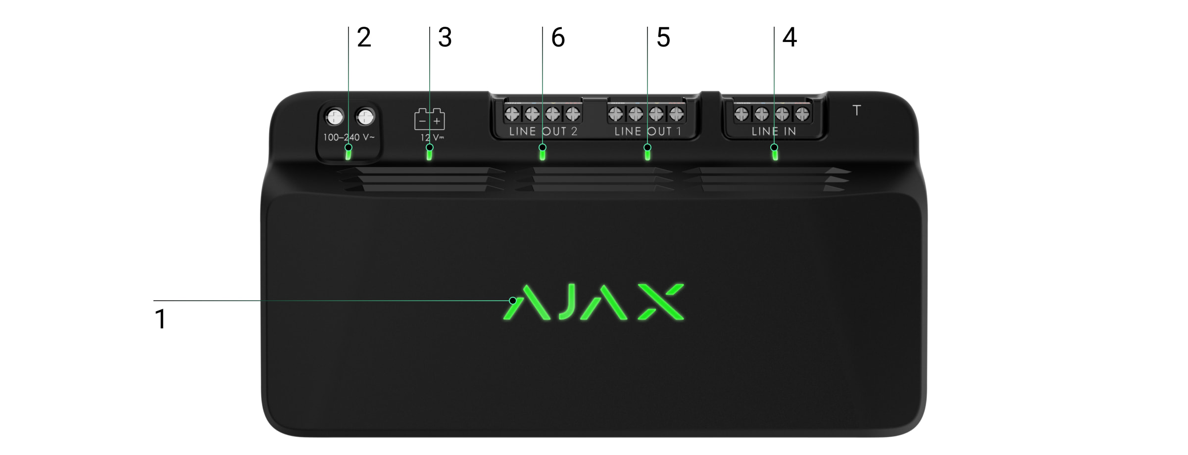
Functional elements
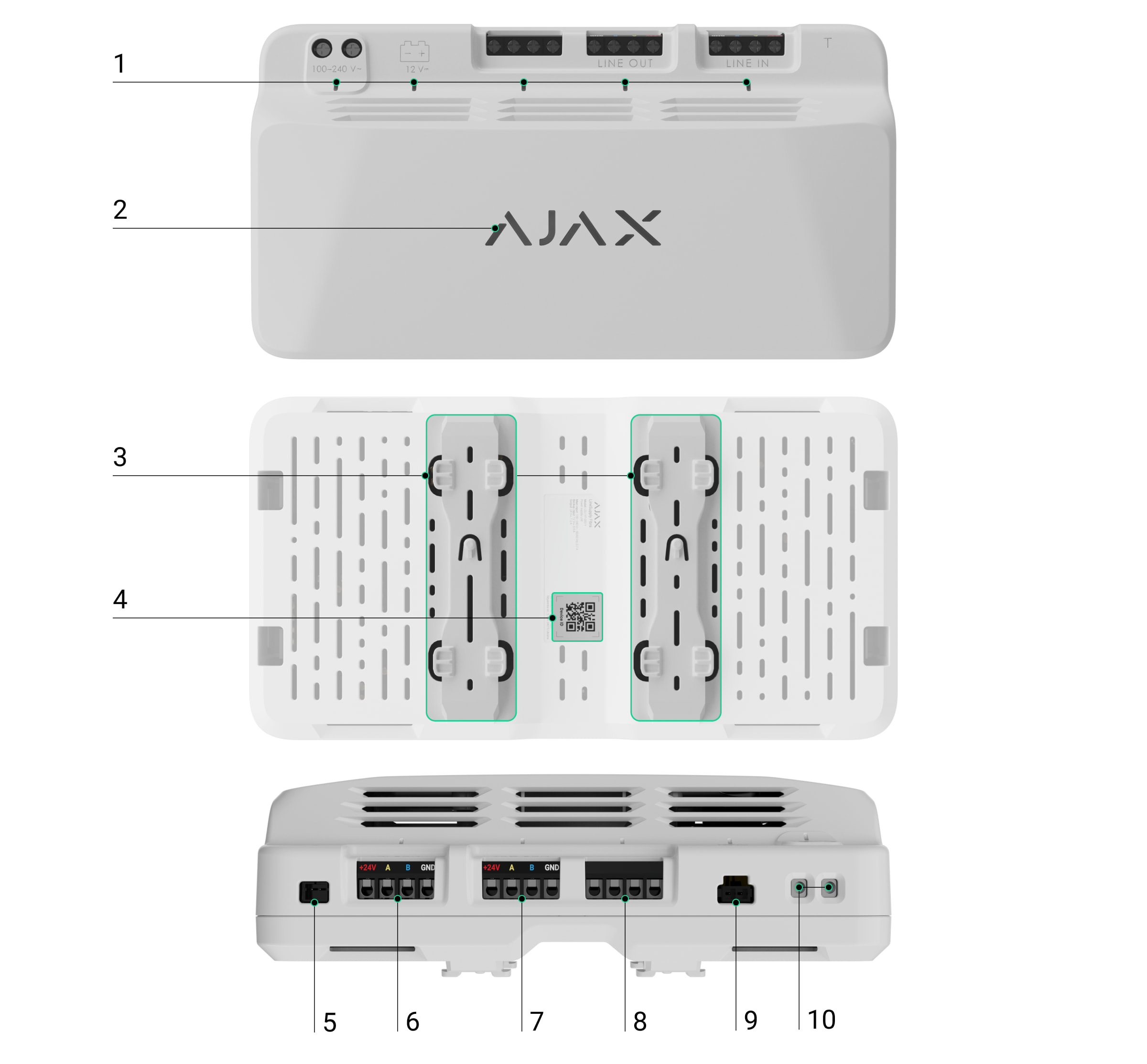
- LED indicators of the module.
- Ajax logo with an LED indicator.
- Rails for installing LineSupply inside a compatible Case (the casing is sold separately).
- QR code with the device ID for adding the module to the Ajax system.
- Connector for attaching the tamper board to the module. The tamper board is included in the Case complete set, which is sold separately.
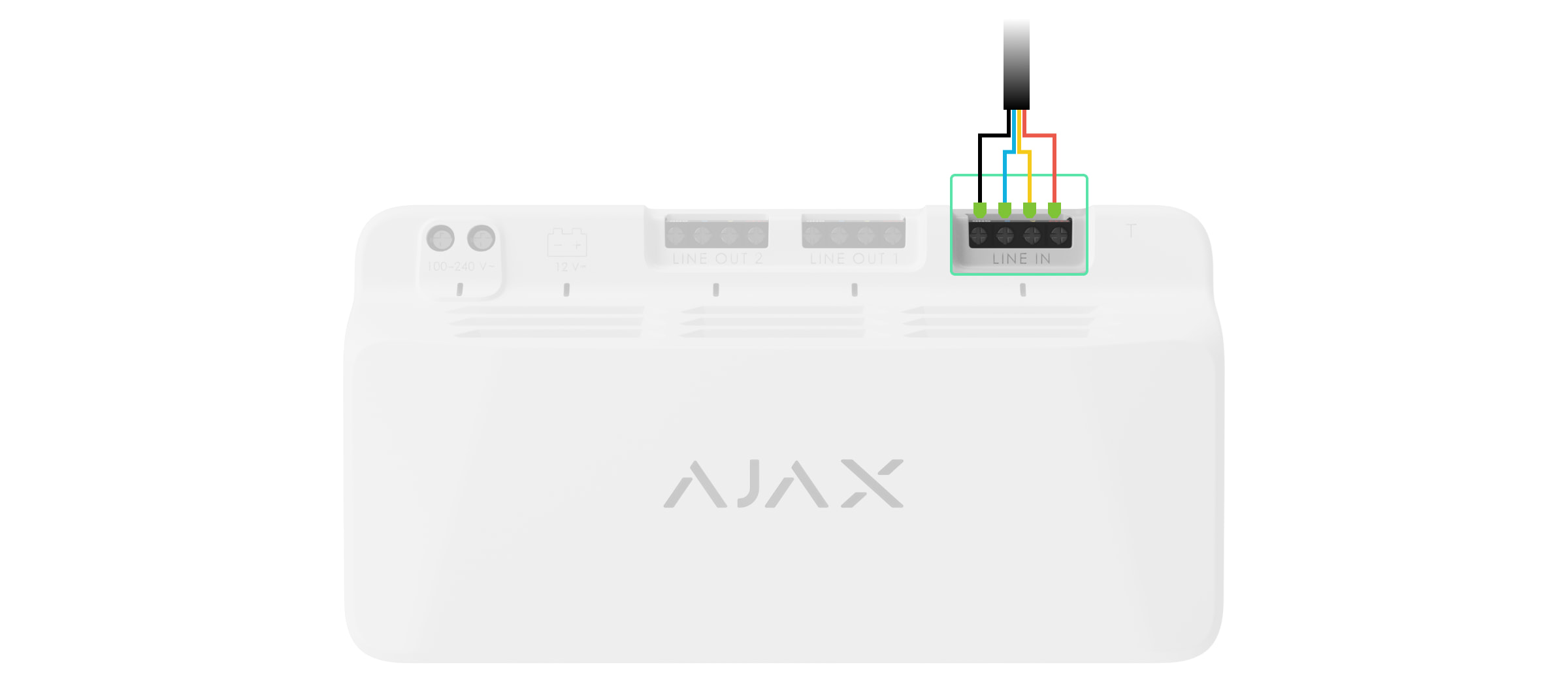
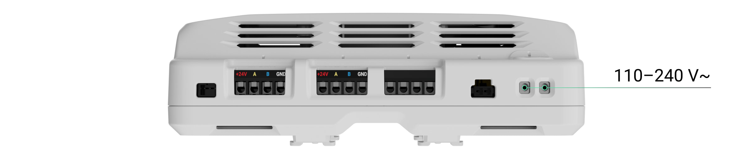
- Input terminals for connecting the Fibra line to LineSupply.
- Output line with terminals for connecting wired devices.
- Unused terminals in this version of the module. In LineSupply (75 W), these serve as a second output line for connecting wired devices.
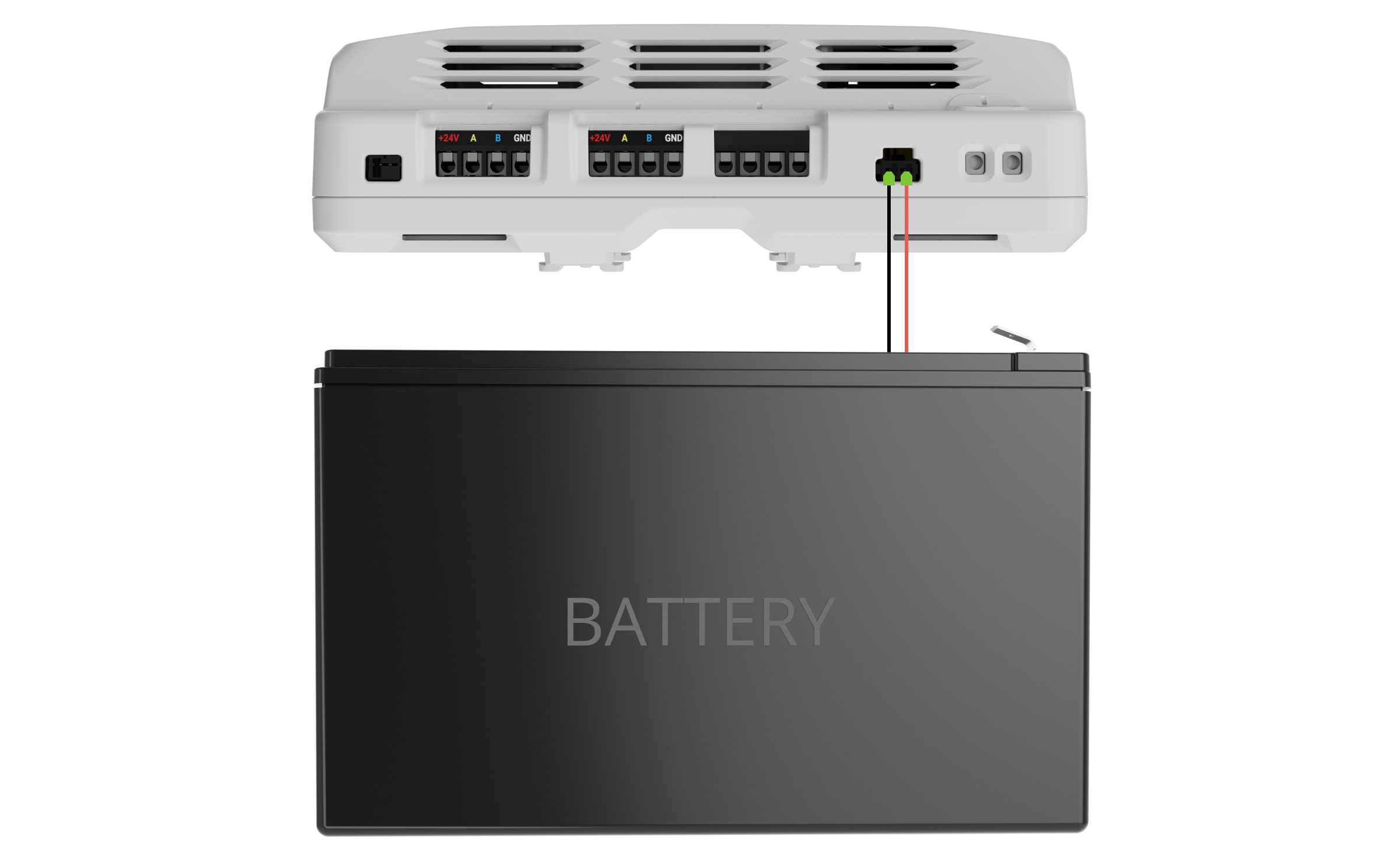
- Connector for connecting a 12 V⎓, 7–18 Ah backup battery.
- Terminals for connecting a 100–240 V~ power supply.

Operating principle
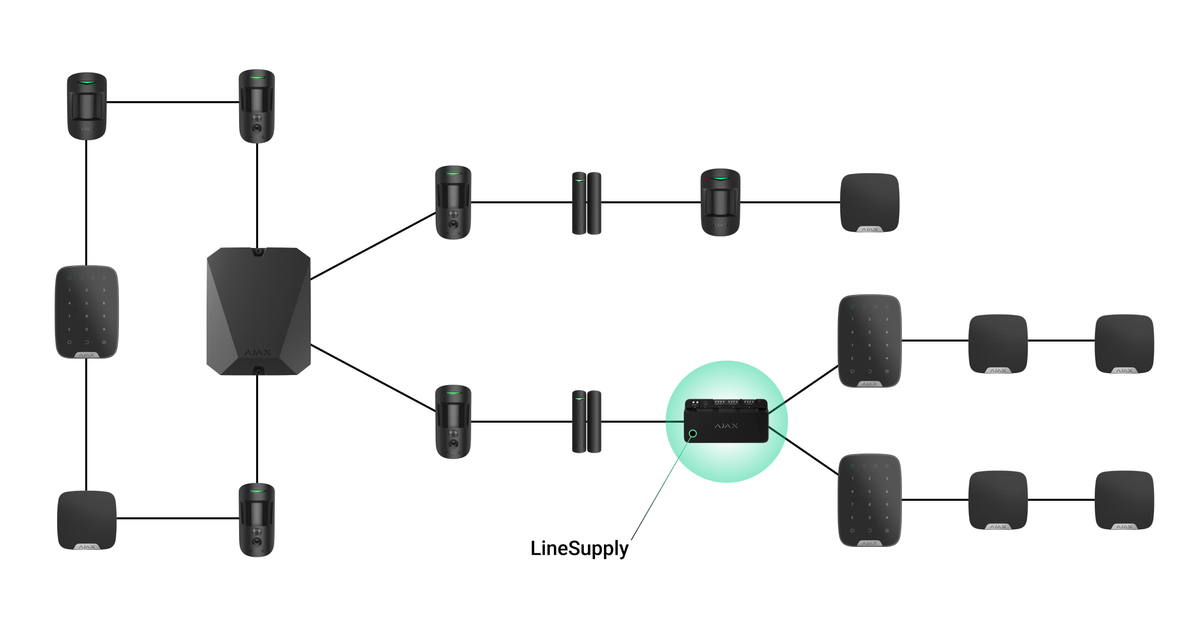
Superior LineSupply Fibra is a module for additional power supply of devices on the Fibra line. You can connect LineSupply at any point along the line, even after another LineSupply.
LineSupply (45 W) features one output line, while LineSupply (75 W) offers two output lines for connecting wired devices. The maximum number of devices that can be connected to the module is determined by the hub (100 devices for Superior Hub Hybrid with standard settings) and the LineSupply output power.
The output power of the module is distributed between the connected devices and the backup battery. For LineSupply (45 W), the distribution is 30 W for devices and 15 W for the backup battery; for LineSupply (75 W) it is 30 W for each output line and 15 W for battery charging.
The module has protection against short circuits and overvoltage on the Fibra output lines. In case of a short circuit or overvoltage, LineSupply turns off the affected output line and attempts to restore power after 12 seconds. If the issue persists, the module de-energizes the line again, repeating this process until normal operation is restored.
LineSupply identifies the malfunction type, and the system sends the corresponding notification to the Ajax apps.
Fibra data transfer protocol
The module uses Fibra technology to transmit alarms and events. It is a wired data transfer protocol for fast and reliable two-way communication between the hub and connected devices.
Sending events to the monitoring station
The Ajax system can transmit alarms to both PRO Desktop monitoring app and the central monitoring station (CMS) in the formats of SurGard (Contact ID), SIA (DC-09), ADEMCO 685, and other protocols.
LineSupply can transmit the following events:
- Tamper alarm and recovery; the module features a connector for attaching a tamper board, included in the Case complete set.
- Tamper board connection/disconnection.
- Low voltage detection on the module output line and voltage restoration to normal values.
- Short circuit detection on the Fibra line and power supply restoration.
- Overvoltage detection on the module output signal lines and voltage restoration to normal values.
- Backup battery connection/disconnection to the module.
- Low backup battery charge and battery charge restoration.
- Backup battery malfunction/restoration.
- Main power supply loss/restoration.
- Connection loss/restoration between LineSupply and the hub.
- Module output line power is turned off/on.
- Malfunction detection; the module cannot charge the backup battery.
- Permanent device deactivation/activation.
- One-time device deactivation/activation.
- Device temperature is out of acceptable limits; temperature restoration to normal values.
Information including the involved line number is transmitted for all events on the LineSupply (75 W) output lines.
When an alarm is received, the operator at the security company’s monitoring station knows what happened and precisely where to dispatch a rapid response team. The addressability of Ajax devices allows sending events to PRO Desktop or the CMS, including the device type, its name, security group, and virtual room. Please note that the list of transmitted parameters might vary depending on the CMS type and the selected communication protocol for the monitoring station.
The device’s ID and number can be found in its states in the Ajax app.
Adding to the system
Superior LineSupply Fibra is compatible only with Superior Hub Hybrid (2G) and Superior Hub Hybrid (4G). Only verified partners can add and configure Fibra devices in Ajax PRO apps.
Before adding a device
- Install an Ajax PRO app.
- Log in to a PRO account or create a new one.
- Select a space or create a new one.

The space functionality is available for apps of such versions or later:
- Ajax Security System 3.0 for iOS;
- Ajax Security System 3.0 for Android;
- Ajax PRO: Tool for Engineers 2.0 for iOS;
- Ajax PRO: Tool for Engineers 2.0 for Android;
- Ajax PRO Desktop 4.0 for macOS;
- Ajax PRO Desktop 4.0 for Windows.
- Add at least one virtual room.
- Add a compatible hub to the space. Ensure the hub is switched on and has internet access via Ethernet, Wi-Fi, and/or mobile network.
- Ensure the space is disarmed, and the hub is not starting an update by checking statuses in the Ajax app.
Connecting to the hub
There are two ways to add devices in the Ajax PRO app: automatically and manually.
- Open the Ajax PRO app and select the hub to which you want to add LineSupply.
- Go to the Devices
 tab and click Add Device.
 - Select Add all Fibra devices. The hub will scan the Fibra lines. After scanning, all devices connected to the hub that have not been added to the system will be displayed.
- Select the desired device from the list. Upon selection, the LED indicator will flash to identify this device.
- Name the device, and select the room and security group if Group Mode is enabled. Click Save.
If the connection attempt fails, verify that the wired connection is correctly set up before trying again. If the maximum number of devices (100 for Superior Hub Hybrid) has already been added to the hub, you will receive an error notification while adding.
Once connected to the hub, the module will appear in the list of hub devices in the Ajax app. The device status update frequency in the list depends on the Jeweller/Fibra settings, with the default value of 36 seconds.
LineSupply works with only one hub. When connected to a new hub, the device stops sending events to the old one.
Adding the module to a new hub does not automatically remove it from the device list of the old hub. This must be done through the Ajax app.
Malfunctions
When a LineSupply malfunction is detected, the Ajax app displays a malfunction counter on the device icon. All malfunctions are indicated in the module states. Fields with malfunctions will be highlighted in red.
A malfunction is displayed if:
- the casing is detached from the surface or its integrity is compromised;
- short circuit on the Fibra line;
- overvoltage on the module output signal lines;
- low voltage on the module output line;
- the backup battery is not installed;
- the backup battery is malfunctioned;
- the backup battery is low;
- the external power supply is disconnected;
- LineSupply module has a malfunction and cannot charge the backup battery;
- the module’s temperature is out of acceptable limits;
- connection with a hub is lost.
If the malfunction occurs on the LineSupply (75 W) output line, the corresponding notification in the Ajax app event feed has its number.
Icons
The icons in the app display some module states. To access them:
- Sign in to the Ajax app.
- Select a hub.
- Go to the Devices tab.
| Icon | Value |
|
Fibra signal strength: displays the signal strength between the hub and the module. |
|
| LineSupply battery charge level, in percentage. | |
| LineSupply temperature threshold has been exceeded. | |
| The backup battery is malfunctioned or not installed. | |
|
LineSupply is permanently deactivated. |
|
|
LineSupply tamper alarm notifications are permanently deactivated. |
|
|
LineSupply is deactivated until the first disarming of the system. |
|
|
LineSupply tamper alarm notifications are deactivated until the first disarming of the system. |
|
| The device has lost connection with the hub or the hub has lost connection with the Ajax Cloud server. | |
|
The device has not been transferred to the new hub. |
States
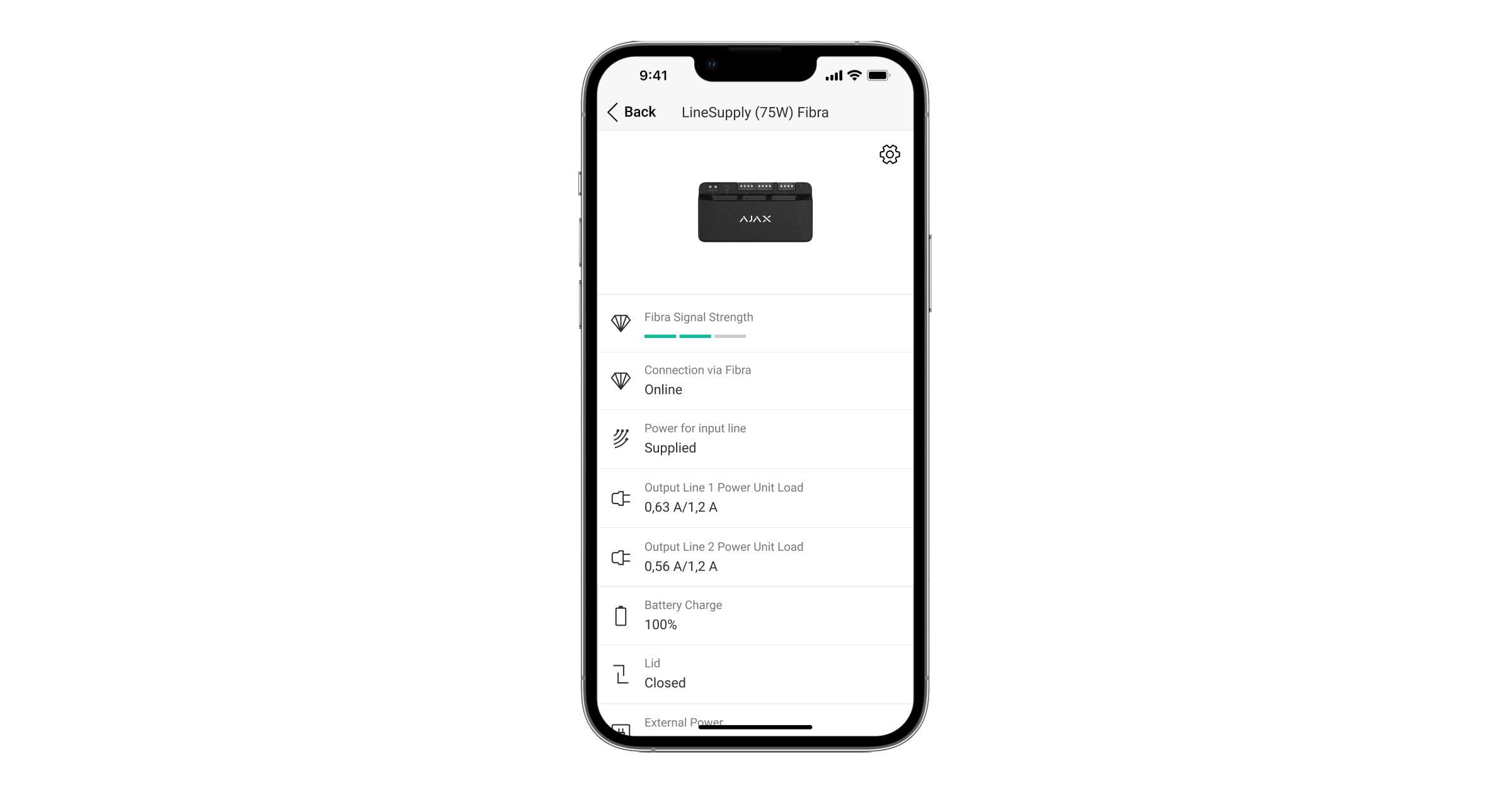
The states include information about the device and its operating parameters. You can find the states of LineSupply in the Ajax app:
- Go to the Devices tab.
- Select LineSupply from the list.
| Parameter | Meaning |
| Data import | Displays the error when transferring data to the new hub:
|
| Malfunction |
Clicking the The field is displayed only if a malfunction is detected. |
| Fibra Signal Strength |
Fibra signal strength between the device and the hub. The recommended value is 2–3 bars. Fibra is a protocol for transmitting LineSupply events and alarms. |
| Connection via Fibra | Connection status on the Fibra channel between the device and the hub:
|
| Power for input line | Power status on the input line:
|
| Power Unit Load / Output Line 1 Power Unit Load |
The current consumed by Fibra devices connected to the module. For LineSupply (75 W), this is the value for the first output line. The module can provide up to 1.2 A of the output current on each line. |
| Output Line 2 Power Unit Load |
The current consumed by Fibra devices connected to the second output line of the module. The module can provide up to 1.2 A of the output current on each line. Displayed only in LineSupply (75 W) states. |
| Battery charge | The backup battery status:
|
| Lid | The tamper status that responds to the casing detachment from the surface or violation of its integrity:
|
| External power | External power supply connection status:
|
| Output line power supply / Output line 1 power supply | Power status on the first output line of the module:
|
| Output line 2 power supply | Power status on the second output line of the module:
Displayed only in LineSupply (75 W) states. |
| Permanent Deactivation | Shows the status of the module permanent deactivation setting:
|
|
One-Time Deactivation
|
Shows the status of the device one-time deactivation setting:
|
| Firmware | Device firmware version. |
| Device ID | Module ID. Also available on the QR code on the device enclosure and its package box. |
| Device No. | Number of the device loop (zone). |
| Line No. | The number of the Fibra line that LineSupply is connected to. |
Settings
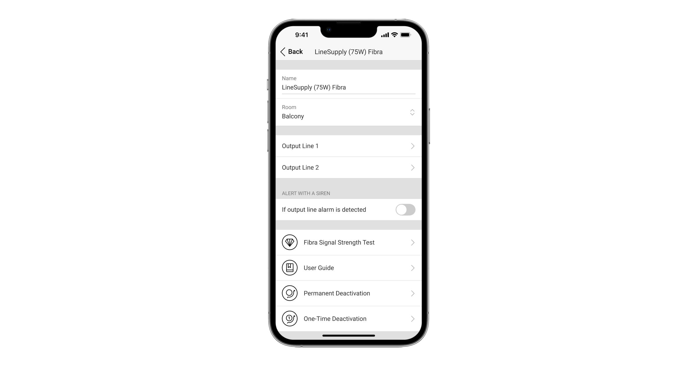
To change the LineSupply settings in the Ajax app:
- Go to the Devices tab.
- Select LineSupply from the list.
- Go to Settings by clicking on the gear icon
 .
. - Set the required parameters.
- Click Back to save the new settings.
| Settings | Value |
| Name |
Name of the module. Displayed in the list of hub devices, SMS text, and notifications in the events feed. To change the name of the device, click on the text field. The name can contain up to 12 Cyrillic characters or up to 24 Latin characters. |
| Room |
Selecting the virtual room to which LineSupply is assigned. The room name is displayed in the text of SMS and notifications in the events feed. |
| Output Line 1/Output Line 2 | |
| Output line power supply |
This option is enabled by default, and the module output line is powered. If the option is deactivated, the output line is not powered. |
| Stop powering line if power supply from hub interrupted | If enabled and the power supply from the hub is interrupted, the module will cut off the power supply to the output line and devices connected to it. |
| Alert with a siren if output line alarm is detected |
When this option is enabled, the sirens added to the system will activate in case of an alarm on the output line (short circuit or overvoltage on the signal lines). The option is disabled by default. |
| Fibra Signal Strength Test |
Switches the device to the Fibra signal strength testing mode. |
| User Guide | Opens LineSupply user manual in the Ajax app. |
| Permanent Deactivation |
Allows the user to deactivate the device without removing it from the system. Three options are available:
|
| One-Time Deactivation |
Allows the user to disable events of the device until the first disarm. Three options are available:
|
| Delete Device | Unpairs the device, disconnects it from the hub, and deletes its settings. |
Indication
LineSupply is equipped with various LED indicators to inform about its states:
- The main indicator.
- Module external power supply indicator.
- Backup battery status indicator.
- Input line connection status indicator.
- Output line 1 power supply status indicator.
- Unused indicator in Superior LineSupply (45 W) Fibra / Output line 2 power status indicator for Superior LineSupply (75 W) Fibra.
| Indicator | Indication | Event |
| Main |
Lights up green. When added automatically — the green LED flashes quickly when LineSupply is selected from the list. When you click Add device, the green LED flashes once. When added manually — the green LED flashes once. |
Standard module indication when it is working correctly. |
| Lights up red. | Malfunction:
|
|
| Input line connection status | Lights up green. | When there is power supply from the hub. |
| Output line 1 power supply status | Lights up green. | When the output line power is on. |
| Output line 2 power supply status |
It is turned off in LineSupply (45 W) module. Lights up green in LineSupply (75 W) module. |
An indicator lights up in LineSupply (75 W) module if the output line is powered. |
| Backup battery status | Lights up red. | If the polarity is reversed when connecting the backup battery. |
| No light. | The backup battery is not installed. | |
| Light up green permanently. | The backup battery is charged. Module external power supply is connected. | |
| Flashes once per 10 seconds. | The backup battery is charged. Module external power supply is disconnected. | |
| In case of alarm, it lights up and goes out smoothly once a minute. | The backup battery is low. | |
| It flashes green every 0.5 seconds. | The backup battery is charging. | |
| Module external power supply status | Lights up green. | When the module external power supply is connected. |
Functionality testing
The Ajax system offers several types of tests to help select the correct installation place for the devices. Tests do not start immediately. However, the waiting time does not exceed the duration of one “hub—device” polling interval. The polling interval can be checked and configured at hub settings (Hub → Settings ![]() → Jeweller/Fibra).
→ Jeweller/Fibra).
To run a test, in the Ajax app:
- Select the required hub.
- Go to the Devices tab.
- Select LineSupply from the list.
- Go to the Settings .
- Run the Fibra Signal Strength Test.
Device placement
Install LineSupply on the line before the Fibra devices with the highest power consumption, which may lack power from the hub. These could be devices like sirens or keypads, for example. LineSupply can also function as a repeater to extend the line’s range.
While you can install the module even after another LineSupply, avoid connecting the module’s Fibra output lines in a Ring topology.
When choosing a location for LineSupply, consider the parameters that affect its operation:
- Fibra signal strength.
- Length of the cable used to connect LineSupply.
- Length of the cable connecting wired devices to LineSupply.
Follow these recommendations when designing the system project for an object. Only professionals should design and install the Ajax system. The list of authorized Ajax partners is available here.
Installing into Case
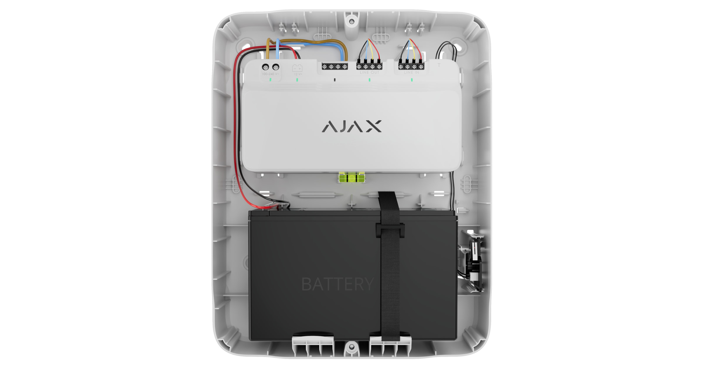
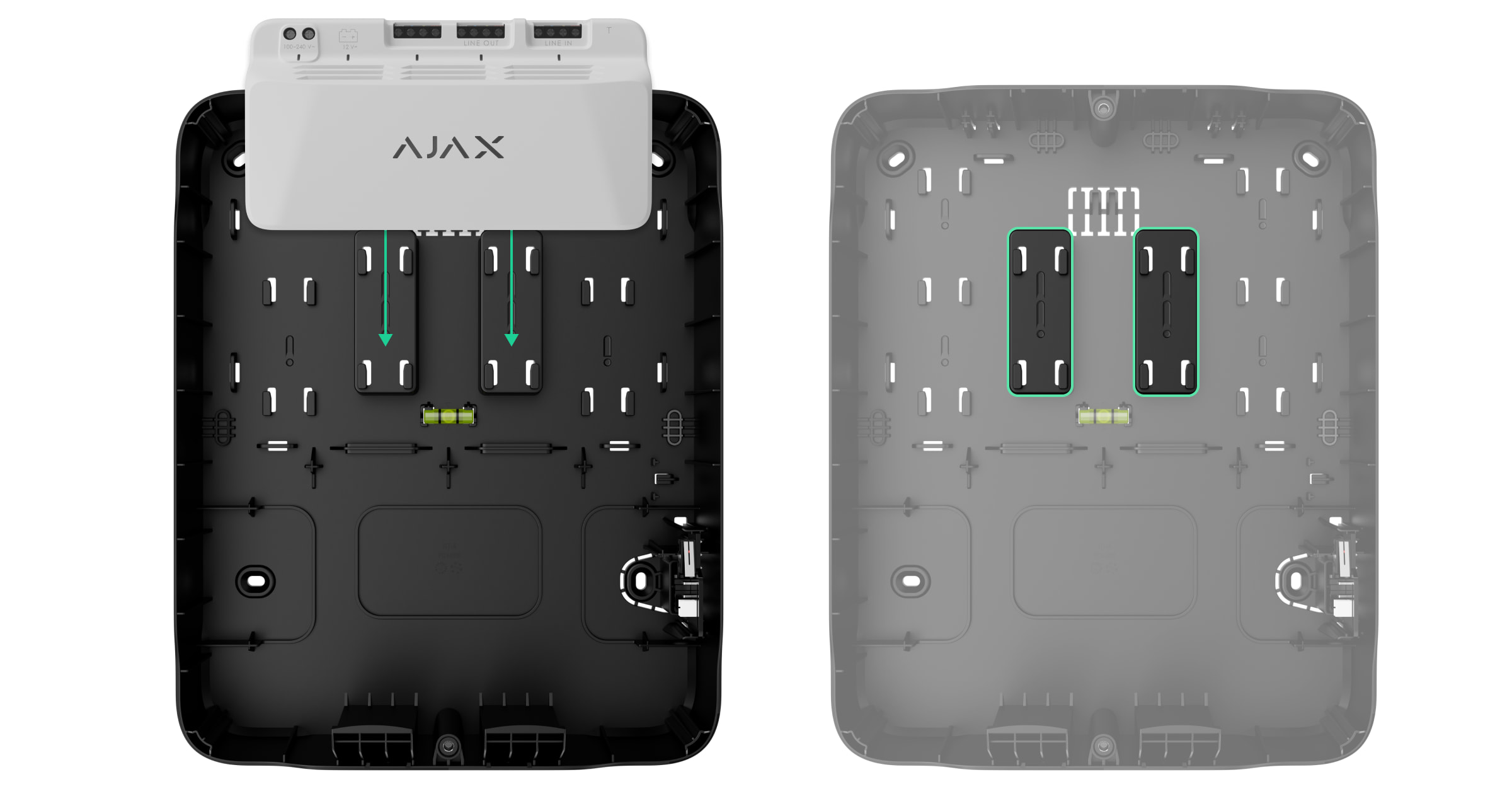
To install LineSupply, use Case C (260) or Case D (430), which are sold separately. You can mount one LineSupply in Case C (260) and several modules or other devices in Case D (430). Use Case configurator to get the most optimal placement of your Fibra devices in the casing.
Each Case is equipped with mounts for the modules, wire channels, and a tamper that can be connected to LineSupply.
 |
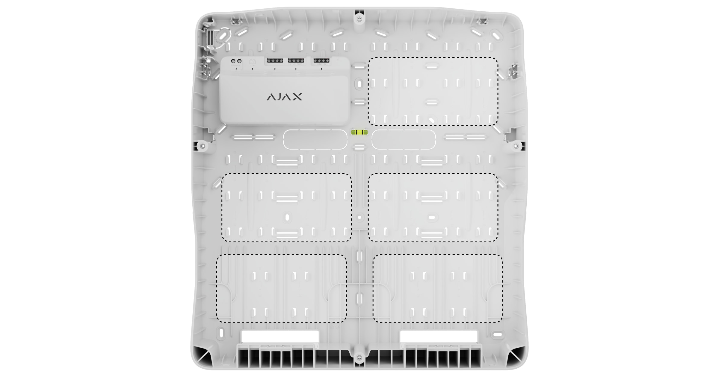 |
| LineSupply in Case C (260) | LineSupply in Case D (430) |
Do not install LineSupply
- Outdoors, as it can lead to module failure.
- Inside premises where temperature and humidity levels exceed the permissible limits, as this can damage the module.
- In places with low or unstable Fibra signal strength, since this might cause a loss of connection with the hub.
Fibra Signal Strength
The Fibra signal strength is determined by the number of undelivered or corrupted data packages over a certain period of time. The icon ![]() in the Devices
in the Devices ![]() tab indicates the signal strength:
tab indicates the signal strength:
- three bars — excellent signal strength;
- two bars — good signal strength;
- one bar — low signal strength, stable operation is not guaranteed;
- crossed out icon — no signal.
Lines Power Test
The test simulates the maximum energy consumption of devices connected to the hub. If the system passes the test successfully, all its devices have enough power in any situation.
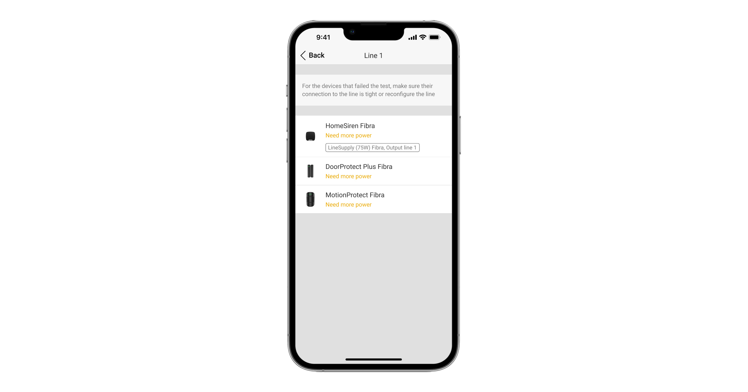
After the test, the app displays a notification with the status of each line:
- test passed;
- test passed with malfunctions;
- test failed.
If Lines Power Test fails or passes with a malfunction, the device list will indicate which devices are connected to the hub via LineSupply.
For devices connected to LineSupply (75 W), the list additionally indicates the number of the output line on which devices are located.
Designing
It is crucial to design the system project properly to ensure the correct installation and configuration of the devices. The design must consider the number and types of devices at the object, their exact locations and installation heights, the length of wired Fibra lines, the type of cable used, and other parameters. Refer to the article to learn tips for designing the Fibra system project.
LineSupply can connect at any point on the Fibra line. When using a U/UTP cat.5 twisted pair cable, the output line length (between LineSupply and the last device) can be up to 2,000 meters. Any Fibra device can be connected to the module’s output line, such as opening detectors, motion detectors, sirens, and keypads. However, the number of wired devices in the system is limited by the module’s output power per line (up to 30 W) and the hub’s technical specification. You can connect up to 100 devices to Superior Hub Hybrid.
While Ajax systems support Beam and Ring topologies, avoid connecting the module’s Fibra output lines in a Ring topology.
Cable length and type
Recommended cable types:
- U/UTP cat.5 4×2×0.51 mm (24 AWG) cable, copper conductor;
- 4×0.22 mm² signal cable, copper conductor.
The maximum line length of up to 2,000 m is relevant when using the recommended cable type. Please note, the wired connection range might vary if other cable types are used. As of now, no other cable types have been tested.
Verification using a calculator
To ensure that the project is designed correctly and the system functions as intended in practice, we have developed a Fibra power supply calculator. It helps to check the communication quality and cable length for wired Fibra devices when designing the system project.
Preparing for installation
Cable arrangement
Before laying cables, check the electrical and fire safety regulations applicable in your region. Strictly follow these standards and regulations. Tips for cable arrangement are available in this article.
Cable routing
Before beginning the installation, we strongly advise reviewing the Device placement section thoroughly. Stick to the outlined system project without deviation. Violation of the basic LineSupply installation rules and the recommendations of this manual may lead to incorrect operation, as well as loss of connection with the device. Tips for cable routing are available in this article.
Preparing cables for connection
First, remove the insulation layer and strip the cable with a special insulation stripper. The ends of the wires inserted into the device terminals must be tinned or crimped with a sleeve. It ensures a reliable connection and protects the conductor from oxidation. Tips for preparing the cables are available in this article.
Installation
- Prepare cable holes in Case in advance.
- Secure Case with the bundled screws using at least two fixing points. Fix Case at a point with a perforated area so its tamper responds to disassembly attempts.
- Turn off the power of lines in the Ajax PRO app:
- Hub → Settings → Lines → Lines Power Supply.
- Hub → Settings
- Route the cable to connect LineSupply to the hub casing. Connect the wires to the required hub line.
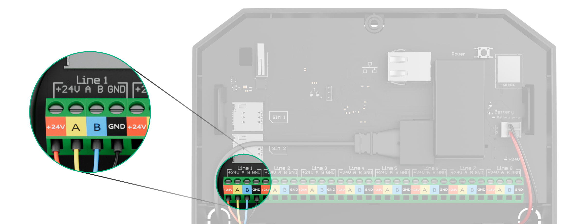
+24V — 24 V⎓ power terminal.
A, B — signal terminals.
GND — ground. - Secure the module in Case using the rails.
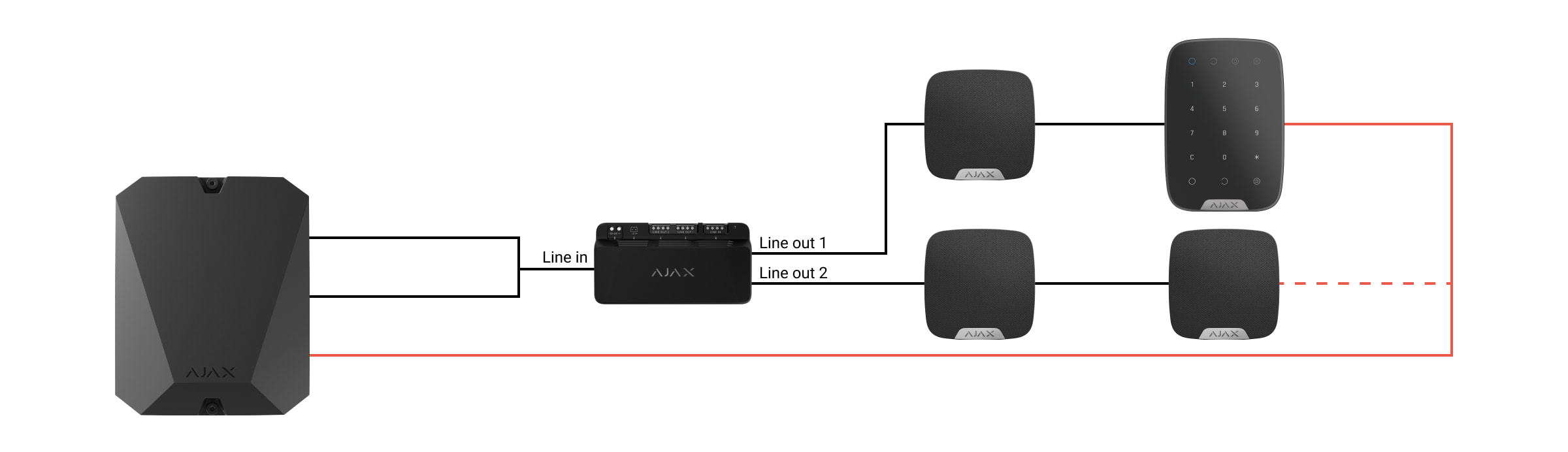
- Connect the wires to the LineSupply input terminals according to the diagram below. Ensure the correct polarity and order of the wire connections. Firmly secure the cable to the terminals.
- Connect the wires to the LineSupply output terminals according to the diagram below. Ensure the correct polarity and order of the wire connections. Secure the cable firmly to the terminals.
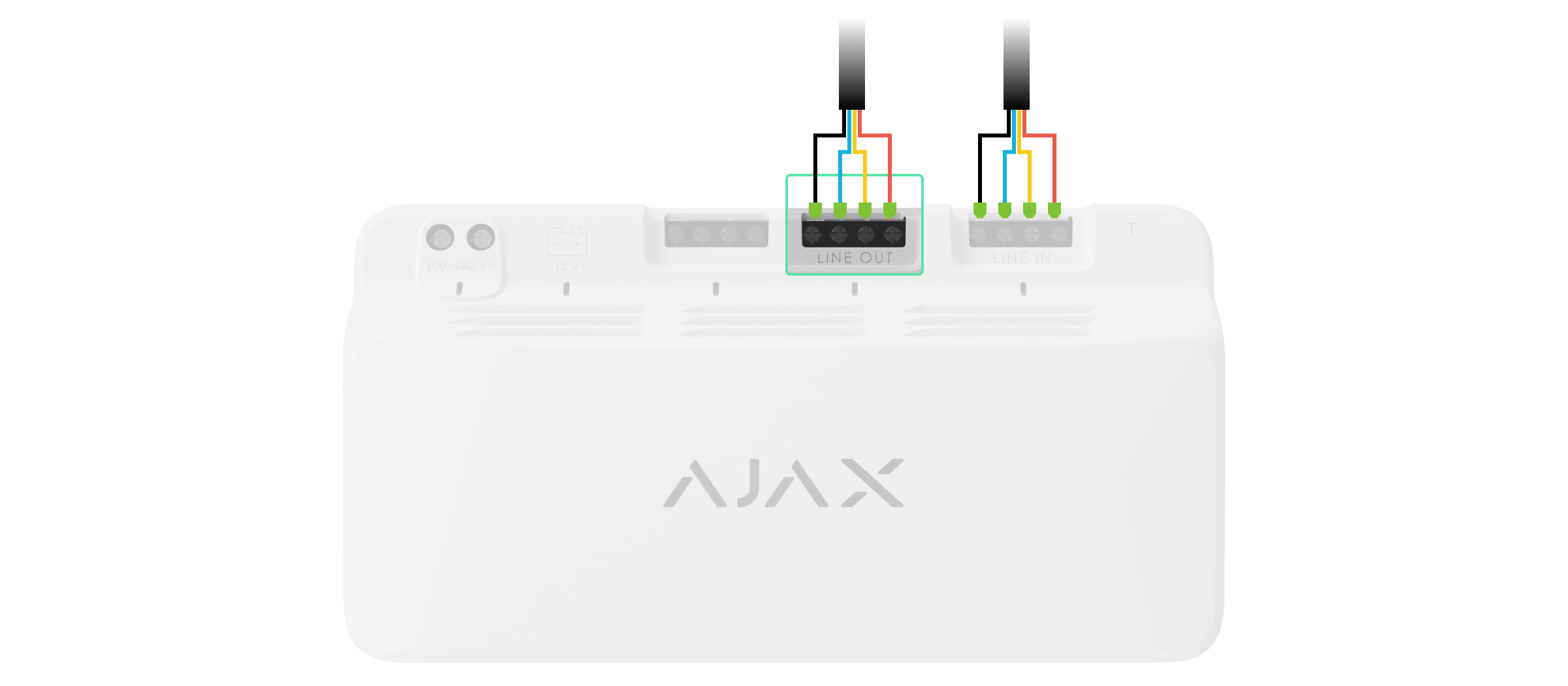
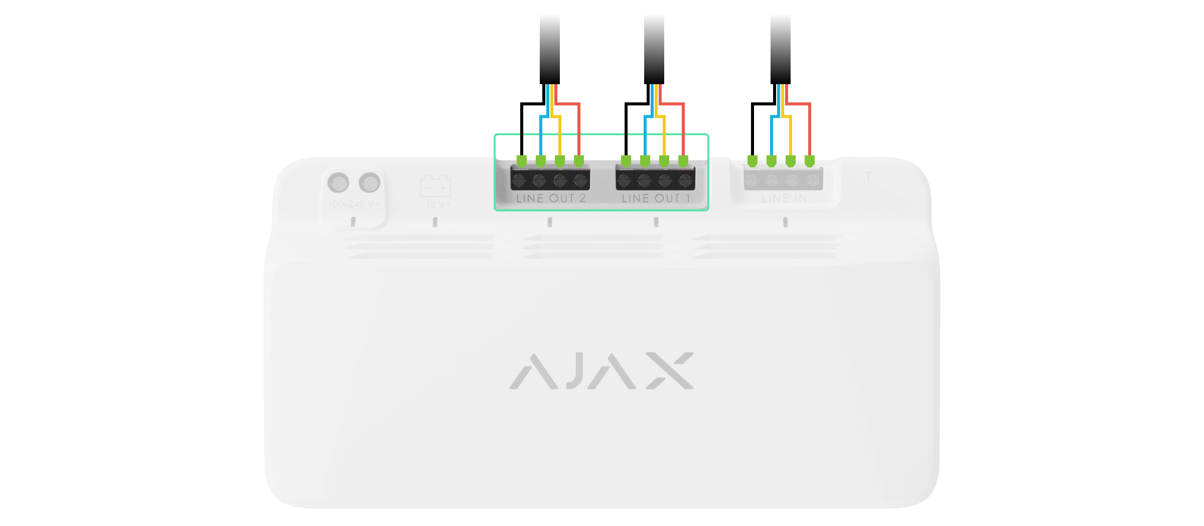
Superior LineSupply (45 W) Fibra Superior LineSupply (75 W) Fibra - Connect the Case tamper board to the appropriate module connector.

- Connect the backup battery to the appropriate module connector. Secure the battery on the special holders provided in Case.
- Connect the main power supply to the appropriate module connector.
- Secure the cable with ties.
- Place the lid on the casing and fasten it with the bundled screws.
- Turn on the power supply of lines in the Ajax PRO app:
- Hub → Settings → Lines → Lines Power Supply.
- Hub → Settings
- Add LineSupply to the hub.
- Add to the hub connected to the module wired devices. Find the algorithm for adding and configuring each device in its user manual.
After adding devices to the hub, their states displayed in the Ajax apps display indicate that they are connected to the hub via LineSupply. For devices connected to LineSupply (75 W), the specific module line number they are connected to is also displayed.
- Run the module functionality testing.
Maintenance
The device does not require maintenance.
Technical specifications
Warranty
Warranty for the Limited Liability Company “Ajax Systems Manufacturing” products is valid for 2 years after the purchase.
If the device does not function correctly, please contact Ajax Technical Support first. In most cases, technical issues can be resolved remotely.
Contact Technical Support:
Manufactured by “AS Manufacturing” LLC
