
Hub (2G) / (4G) Jeweller is a control panel of the Ajax system. It controls the operation of connected devices and interacts with users, PROs, and security companies.
Please note that Hub (2G) / (4G) Jeweller does not support some Ajax devices. Refer to the Ajax devices compatibility table for a detailed list of compatible devices.
Hub (2G) / (4G) Jeweller requires internet access to connect to the Ajax Cloud server. The available communication channels are Ethernet and a SIM card. Both Hub (2G) Jeweller and Hub (4G) Jeweller have identical technical characteristics and settings, differing only in the GSM modem. The 2G version supports only 2G networks, and the 4G version supports 4G (LTE) networks.
Use both communication channels to ensure more reliable communication between the hub and Ajax Cloud, if possible.
Connecting to Ajax Cloud is necessary for configuring and managing the system through Ajax apps, transferring notifications about alarms or events, and updating the software. All data on Ajax Cloud is stored under multilevel protection, and information is exchanged with the hub via an encrypted channel.
You can efficiently manage the system and quickly respond to alarms or notifications with iOS, Android, macOS, and Windows apps. Hub admin or PRO with the rights to configure the system can choose the events to inform users about and how to notify them — by push notifications or SMS.
Functional elements
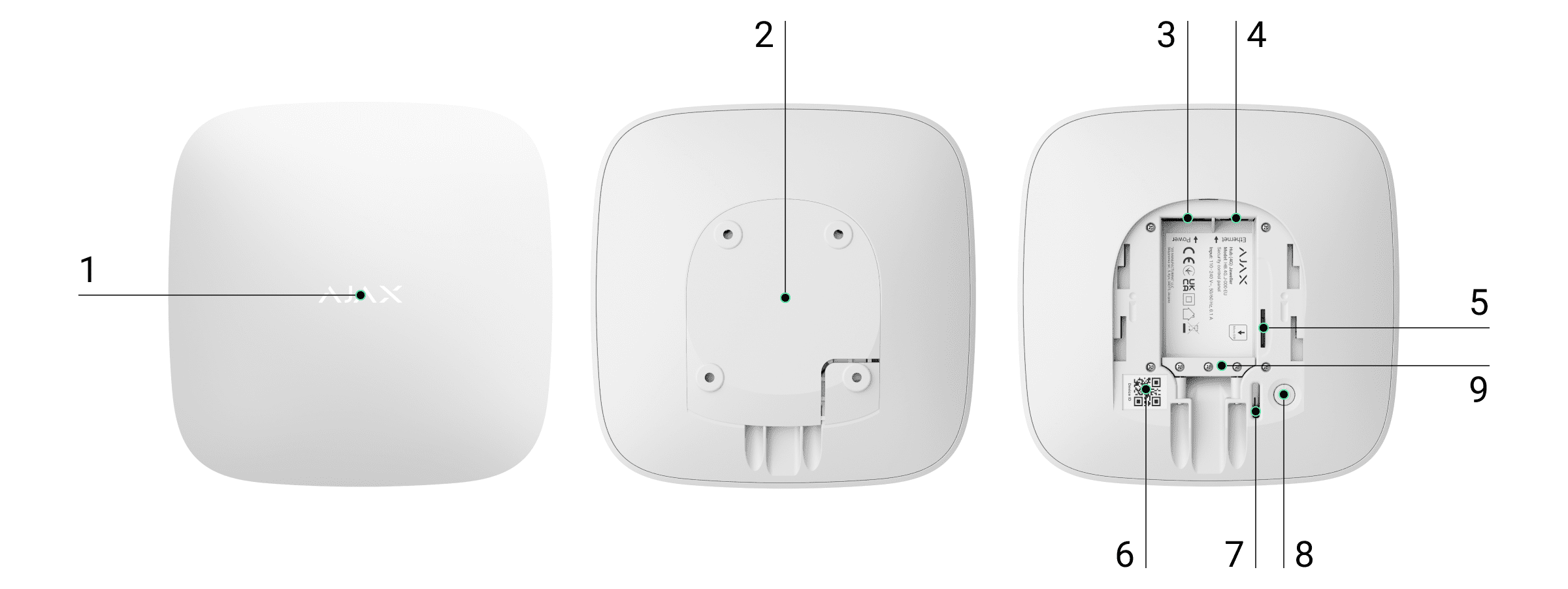
- LED logo indicating the hub status.
- The SmartBracket mounting panel. Slide it down with force to remove it.

Do not break off the perforated part of the mounting panel. It is required for actuating the tamper in case of any attempt to dismantle the hub.
- Power cable socket.
- Ethernet cable socket.
- Slot for the micro SIM.
- QR code.
- Tamper.
- Power button.
- Сable retainer clamp.
Operating principle
Hub (2G) / (4G) Jeweller monitors the system operation by communicating with added devices via the Jeweller encrypted protocol. The communication range is up to 2,000 m in an open space (for example, without walls, doors, or inter-floor constructions). If the detector is triggered, the system immediately raises the alarm, runs scenarios, and notifies the security company’s central monitoring station (CMS) and system users about the incident.
You can add up to 100 Ajax devices to the hub to protect the facility against intrusion, fire, and flooding. Control electrical appliances either automatically using scenarios or manually via Ajax apps.
Sabotage protection
Hub (2G) / (4G) Jeweller has two communication channels for connecting to the Ajax Cloud server: Ethernet and a SIM card. This allows you to connect the device to different communication providers simultaneously. If one communication channel becomes unavailable, the hub automatically switches to another and notifies the security company’s CMS and system users.
In case of interference at Jeweller frequencies or attempted jamming, the system seamlessly switches to an available radio frequency and sends notifications to the security company’s CMS and system users.
The hub regularly checks the communication quality with all added devices. If any device loses connection with the hub, a notification about the incident will be sent to all system users (depending on the settings) and the security company’s CMS.
No one can disconnect the hub unnoticed, even when the facility is disarmed. If an intruder attempts to dismount the device, it immediately triggers the tamper. System users and the security company will receive notifications about triggering.
The hub regularly checks the connection with the Ajax Cloud server. The polling interval is specified in the hub settings. By default, the server notifies users and the security company within 60 seconds after losing the connection.
The built-in backup battery ensures up to 15 hours of autonomous operation when the Ethernet connection is switched off. Due to this, the system continues to operate even if the power supply is cut off at the facility. To increase battery life or connect the hub to a 6 V⎓ or 12–24 V⎓ grid, use a power supply unit:
Hub (2G) Jeweller — 12V PSU for Hub/Hub Plus/ReX
Hub (4G) Jeweller — 6V PSU for Hub 2/Hub 2 Plus/ReX 2, 12–24V PSU for Hub 2/Hub 2 Plus/ReX 2
OS Malevich
Hub (2G) / (4G) Jeweller is run by the real-time operating system OS Malevich. The system is immune to viruses and cyberattacks.
Video surveillance connection
Hub (2G) / (4G) Jeweller is compatible with Ajax cameras and NVRs and with third-party cameras that support RTSP protocol or SDK integration.
Cameras and NVRs that can be connected to Hub (2G) / (4G) Jeweller:
| Devices | Quantity |
| Ajax cameras via Ajax NVRs | up to 224 |
| Third-party cameras via Ajax NVRs using ONVIF | up to 224 |
| Standalone Ajax cameras | up to 200 |
| Standalone third-party cameras using RTSP or SDK | up to 10 |
Automation scenarios
Use scenarios to automate the system and decrease the number of routine actions. Adjust the security schedule and program actions of automation devices in response to an alarm, Button press, or by schedule. A scenario can be created remotely in the Ajax app.
Hub (2G) / (4G) Jeweller doesn’t support scenarios by temperature, humidity, CO2 concentration, and touching LightSwitch Jeweller.
LED indication
Hub has two LED indication modes:
- Hub – Server Connection.
- British Disco.
Hub – Server Connection
Hub – Server Connection mode is enabled by default. The hub LED has a list of indications showing the system state or events occurring. The Ajax logo on the front side of the hub can light up red, white, purple, yellow, blue, or green, depending on the state.
| Indication | Event | Note |
| Lights up white. | Two communication channels are connected: Ethernet and a SIM card. |
If the external power supply is off, the indicator flashes every 10 seconds. In case of a power outage, the hub indicator starts flashing not immediately, but after 180 seconds. |
| Lights up green. |
One communication channel is connected: Ethernet or a SIM card. |
If the external power supply is off, the indicator flashes every 10 seconds. In case of a power outage, the hub indicator starts flashing not immediately, but after 180 seconds. |
| Lights up red. | The hub is not connected to the internet, or there is no connection with the Ajax Cloud server. |
If the external power supply is off, the indicator flashes every 10 seconds. In case of a power outage, the hub indicator starts flashing not immediately, but after 180 seconds. |
| Lights up for 180 seconds after a power outage, then flashes every 10 seconds. | The external power supply is disconnected. | The color of the LED indication depends on the number of connected communication channels. |
| Flashes red. | The hub is reset to factory settings. |
If you see an indication not listed in this user manual, please contact our Technical Support.
Access to indications
Hub users can see the British Disco indication after they:
- arm/disarm the system using the Ajax keypad;
- enter the correct user ID or personal code on the keypad and perform an action that has already been performed (for example, the system is disarmed, and the disarm button is pressed on the keypad);
- press the button on SpaceControl to arm/disarm the system or enable Night Mode;
- arm/disarm the system using Ajax apps.
The function can be enabled in the hub settings in the PRO app (Hub → Settings → Services → LED indication).
Indication is available for hubs with firmware version OS Malevich 2.14 or higher and in apps of the following versions or higher:
- Ajax PRO: Tool for Engineers 2.22.2 for iOS.
- Ajax PRO: Tool for Engineers 2.25.2 for Android.
- Ajax PRO Desktop 3.5.2 for macOS.
- Ajax PRO Desktop 3.5.2 for Windows.
| Indication | Event | Note |
| Changing the hub state | ||
| White LED flashes once per second. | Two-Stage Arming or Delay When Leaving. | One of the devices is performing Two-Stage Arming or Delay When Leaving. |
| Green LED flashes once per second. | Entry indication. | One of the devices is performing Delay When Entering. |
| White LED lights up for 2 seconds. | Arming is completed. | The hub (or one of the groups) is changing its state from Disarmed to Armed. |
| Green LED lights up for 2 seconds. | Disarming is completed. | The hub (or one of the groups) is changing its state from Armed to Disarmed. |
| Alerts and Malfunctions | ||
| Red and purple LEDs flash alternately for 5 seconds. | Confirmed hold-up alarm. |
There is an unrestored state after a confirmed hold-up alarm. The indication is displayed only if Restoration after a confirmed hold-up alarm is enabled in the settings. |
| Red LED lights up for 5 seconds. | Single hold-up alarm. |
There is an unrestored state after a single hold-up alarm. The indication is not displayed if there is a confirmed hold-up alarm state. The indication is displayed only if Restoration after a single hold-up alarm is enabled in the settings. |
| Red LED flashes. | The number of flashes equals the Device No. of a hold-up device (DoubleButton) that first generated the hold-up alarm. | There is an unrestored state after a confirmed or single hold-up alarm:
or
|
| Yellow and purple LEDs flash alternately for 5 seconds. | Confirmed intrusion alarm. |
There is an unrestored state after a confirmed intrusion alarm. The indication is displayed only if Restoration after a confirmed intrusion alarm is enabled in the settings. |
| Yellow LED lights up for 5 seconds. | Single intrusion alarm. |
There is an unrestored state after the intrusion alarm. The indication is not displayed if there is a confirmed intrusion alarm condition. The indication is displayed only if Restoration after a single intrusion alarm is enabled in the settings. |
| Yellow LED flashes. | The number of flashes equals the Device No. of the device that first generated the intrusion alarm. | There is an unrestored state after a confirmed or single intrusion alarm:
or
|
| Red and blue LEDs flash alternately for 5 seconds. | Lid opening. |
There is an unrestored state of a tamper or an open lid on any device or the hub. The indication is displayed only if Restoration after lid opening is enabled in the settings. |
| Yellow and blue LEDs flash alternately for 5 seconds. | Other malfunctions. |
There is an unrestored fault state or a malfunction of any device or the hub. The indication is displayed only if Restoration after other malfunctions is enabled in the settings. Currently, Restoration after faults is not available in Ajax apps. |
| Dark blue LED lights up for 5 seconds. | Permanent deactivation. | One of the devices is temporarily deactivated, or the lid state notifications are disabled. |
| Blue LED lights up for 5 seconds. | Automatic deactivation. | One of the devices is automatically deactivated by an opening timer or the number of detections. |
| Green and blue LEDs flash alternately. |
Alarm timer expiration. |
Displayed after the alarm timer expires (to confirm the alarm). |
When nothing happens in the system (no alarm, malfunction, lid opening, etc.), the LED displays two hub states:
- Armed / Partially armed / Night Mode enabled — the LED lights up white.
- Disarmed — the LED lights up green.
In hubs with firmware OS Malevich 2.15.2 and higher, the LED lights up green when the hub is set to Armed / Partially armed / Night Mode enabled.
Alert indication
If the system is disarmed and any of the indications from the table are present, the yellow LED flashes once per second.
In case there are several states in the system, the indications are displayed consecutively in the same sequence as shown in the table.
Ajax account
To configure the system, install the Ajax app and create an account. Installers, security and monitoring companies use Ajax PRO accounts to configure the system for users.
There is no need to create a new account for each hub, as one account can manage multiple systems. Separate access rights can be configured for each hub if needed.
Both user and system settings, as well as parameters of connected devices are stored in the hub. Changing the hub admin, adding or removing users does not reset the settings of devices added to the hub.
Connecting the hub to Ajax Cloud
- Remove the SmartBracket mounting panel by shifting it down with force.
- Connect the power supply and Ethernet cables to the appropriate sockets.
1 — Power cable socket.
2 — Ethernet cable socket.
3 — Slot for the micro SIM.
4 — Cable retainer clamp. - Press and hold the power button for 2 seconds until the logo lights up. The hub needs approximately 2 minutes to identify the available communication channels.


The bright green or white logo color indicates that the hub is connected to Ajax Cloud.
If the Ethernet connection does not occur automatically, disable proxy and filtration by MAC addresses and enable DHCP in the router settings — the hub will receive an IP address. During the next setup, you will be able to set a static IP address in Ajax apps.
To connect the hub to the GSM network, you need a micro SIM card with a disabled PIN code request (you can disable it using the mobile phone) and a sufficient amount of funds on the account to pay for the GPRS, and SMS services.
In some regions, Hub (2G) / (4G) Jeweller is sold with the Ajax SIM card or a third-party SIM card.
If the hub is not connected to the cellular network, use Ethernet to set up the network parameters: roaming, APN access point, username, and password. Contact your telecom operator to find out these options.
Adding a hub to the Ajax app
Granting access to all system functions (to display notifications in particular) is a mandatory condition for managing the Ajax system via the smartphone/tablet.
- Open the Ajax app and log in to your account.
- Open the Add Hub menu and select how to add a new hub: manually or using step-by-step tutorial.
- At the registration stage, type the name of the hub and scan the QR code under the SmartBracket mounting panel (or enter the ID manually).
- Wait until the hub is registered and displayed in the app.

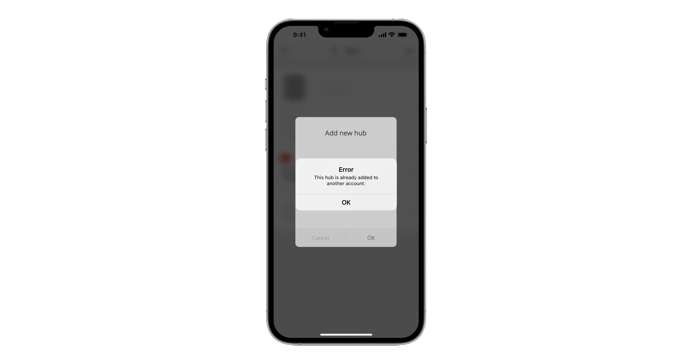
If there are already users on the hub, the hub admin, PRO with the rights to configure the system, or the installation company maintaining the selected hub can add your account. You will be notified that the hub has already been added to another account. Contact our Technical Support to determine who has admin rights on the hub.
Malfunctions
The hub may notify about malfunctions. Clicking on ![]() opens the list of all malfunctions. The Malfunctions field is available in device States and is displayed only if a malfunction is detected, e.g.:
opens the list of all malfunctions. The Malfunctions field is available in device States and is displayed only if a malfunction is detected, e.g.:
- no external power supply;
- low battery charge;
- lid opening;
- high level of interference at Jeweller frequencies.
Icons
Icons display some hub states. You can see them in the Ajax app in the Devices ![]() menu.
menu.
| Icons | Meaning |
| The SIM card operates in a 2G network. | |
|
The SIM card operates in a 4G (LTE) network. Available for Hub (4G) Jeweller only. |
|
| The SIM card is not installed. | |
| The SIM card is defective or has a PIN code on it. | |
| The hub battery charge level. Displayed in 5% increments. | |
| The hub malfunction is detected. The list is available in the hub states menu. | |
| The hub is directly connected to the security company’s CMS. | |
| The hub has lost connection with the security company’s CMS via a direct connection. |
States

States can be found in the Ajax app:
- Select the hub if you have several of them or if you are using a PRO app.
- Go to the Devices tab.
- Select Hub (2G) / (4G) Jeweller from the list.
| Parameter | Meaning |
| Malfunction |
Clicking The field appears only if a malfunction is detected. |
| System Restore Required |
The field appears only if the appropriate option is enabled, and some alarms and/or malfunctions should be fixed before arming. |
| Cellular signal strength |
Shows the signal strength of the cellular network for an active SIM card. We recommend installing the hub in places with the signal strength of 2–3 bars. If the signal strength is weak (0 or 1 bar), the hub cannot send an SMS about an event or alarm. |
| Connection | Connection status between the hub and Ajax Cloud:
|
| Battery Charge |
Battery level of the device. Displayed as a percentage. |
| Lid | Status of the tamper that responds to hub dismantling:
|
| External Power | Supply connection status:
|
| Cellular Data | The hub connection status to the mobile Internet:
If the hub has enough funds on the account or has bonus SMS it can send SMS messages even if the Not connected status is displayed in this field. |
| Ethernet | Status of the hub internet connection via Ethernet:
|
| Active SIM | Displays active SIM card. |
| Average Noise (dBm) |
Noise power level at Jeweller frequencies at the hub installation site. The acceptable value is 80 dBm or lower. |
| Monitoring Station | The status of the hub’s direct connection to the security company’s CMS:
If this field is displayed, the security company uses a direct connection to receive events and system alarms. |
| Hub model | Hub model name. |
| Hardware | Hardware version. Cannot be updated. |
| Firmware | Firmware version. Can be updated remotely. |
| Device ID | Hub ID / serial number. Also located on the device box, circuit board, and the QR code under the SmartBracket mounting panel. |
| IMEI |
A unique 15-digit serial number for identifying the hub’s modem on a GSM network. It is shown only when a SIM card is installed in the hub. Displayed on Hub 4G Jeweller only. |
Settings
Settings can be changed in the Ajax app:
- Select the hub if you have several of them or if you are using a PRO app.
- Go to the Devices tab.
- Select Hub (2G) / (4G) Jeweller from the list.
- Go to Settings by clicking on the gear icon in the upper right corner.
- Set the required parameters.
- Click Back to save the new settings.
Allows setting up the main picture for the Ajax system. It is displayed in the hub selection menu and helps to identify the required object.
To change or set a photo, click on the camera icon and set up the desired picture.
The hub name is displayed in the SMS and push notification text. The name can contain up to 12 Cyrillic characters or 24 Latin characters.
This category allows you to invite and delete users, edit their rights, and define how the system notifies users about events and alarms.
To change the settings for a specific user, click on their username in the list of active users.
User Settings
User Role — selecting the level of access to the system management and configuring: Admin or User.
Notification Settings — an admin or PRO with the rights to configure the system can choose the events to inform about and how to notify users: by push notifications or SMS.
Privacy Settings Management — when enabled, an admin or PRO with rights to configure the system can control other users’ access to surveillance cameras and NVRs.
Permissions
This setting allows you to grant access selectively to manage:
- Security Mode Change;
- System Settings;
- Panic;
- Home Automation Control;
- Chime Activation;
- Fire Alarms Muting;
- Groups.
User Passcode
Passcode Settings — is used for identifying users when they arm/disarm the system with a keypad.
Restoration After Alarm
The Restoration After Alarm feature does not allow arming the system if an alarm has been registered previously. For arming, the system should be restored by an authorized user or PRO user. The types of alarms that require system restoration are defined when configuring the function.
Delete User
This setting is used for removing the user from the hub.
The category is available for users with the right to manage privacy settings. The settings apply to surveillance cameras and Ajax NVRs integrated into the system.
Permissions
- Users — setting up levels of access to surveillance cameras and NVRs for system users.
- Installers — setting up levels of access to surveillance cameras and NVRs for professional installers.
- Companies — setting up levels of access to surveillance cameras and NVRs for monitoring and installation companies.
Settings for wired internet connection.
- Ethernet — allows you to enable and disable Ethernet on the hub.
Connection Type — selection of the type of the hub IP address to receive: dynamic or static. - DHCP
- Static
IP Address — IP address of the hub.
Subnet Mask — subnet mask in which the hub operates.
Gateway — gateway used by the hub.
DNS — DNS of the hub.
Enabling/disabling cellular communication, configuring connections, and checking accounts.
Modem settings
- Cellular Data — disables and enables a SIM card on the hub.
- Roaming — if it is enabled, a SIM card installed in the hub can work in roaming.
- Ignore Network Registration Error — when this setting is enabled, the hub ignores errors when trying to connect via a SIM card. Enable this option if a SIM card cannot connect to the network.
- Disable communication check with the operator — when this setting is enabled, the hub ignores operator communication errors. Enable this option if a SIM card cannot connect to the network.
SIM cards
- SIM 1 — displays the number of installed SIM cards. Click on the field to go to the SIM card settings.
SIM card settings
- APN, Username, and Password — settings for connecting to the internet via a SIM card. To find out your cellular operator’s settings, contact your provider’s support service.
Mobile data usage
- Incoming — the amount of data received by the hub. Displayed in KB or MB.
- Outgoing — the amount of data sent by the hub. Displayed in KB or MB.
Remember that data is calculated by the hub and may differ from your operator’s statistics.
Reset Statistics — resets statistics on incoming and outgoing traffic.
Configuring reminders for arming/disarming the system when crossing a specified area. The user’s location is determined using the smartphone GPS module.
Setting up keypad passwords for people who are not registered in the system.
Hub (2G) Jeweller does not support access codes.
With the OS Malevich 2.13.1 update, we have also added the ability to create a password for people who are not connected to the hub. This is convenient, for example, to provide a cleaning company with access to security management. Knowing the access code, you just need to enter it on the Ajax keypad to arm or disarm the system.
To set up an access code for an unregistered person in the system:
- Press Add code.
- Set up Username and Access Code.
- Press Add.
If you want to set up a duress code, change an access code, settings for access to groups, Night mode, code ID, temporarily disable or delete this code, select it in the list, and make changes.
The created access codes are valid for all keypads connected to the hub. Hub (4G) Jeweller supports up to 50 access codes.
Group mode configuration. Groups combine system devices regardless of their physical location and make security management more convenient and flexible. Up to 9 groups can be created on Hub (2G) / (4G) Jeweller.
Starts the detection zone test for connected detectors. This test determines whether the detectors operate correctly and defines the distance at which they detect alarms.
Configure the hub – detector ping interval. The settings determine how frequently the hub communicates with devices and how quickly the loss of connection is detected.
- Detector Ping Interval, sec — determines the frequency of connected devices polling by the hub. The shorter interval (in seconds) means faster delivery of the events between the hub and connected devices (36 seconds by default).
- Number of missed pings to determine connection failure — a counter of undelivered packets (8 packets by default).
The time before raising the alarm by the communication loss between hub and device is calculated with the following formula:
Detector Ping Interval × Number of missed pings to determine connection failure
It is important to keep in mind that the reduction in the polling interval reduces the bundled battery life.
Note that the ping interval reduces the maximum number of connected devices:
| Detector Ping Interval | Connection limit |
| 12 seconds | 39 devices |
| 24 seconds | 79 devices |
| 36 and more seconds | 100 devices |
Irrespective of the settings, you can connect up to 10 sirens or keypads with a built-in buzzer and 1 range extender to the hub.
Group of hub service settings. These are divided into 2 groups: general settings and advanced settings.
General settings
Time zone
Selecting the time zone in which the hub operates. It is used for scenarios by schedule. Therefore, before creating scenarios, set the correct time zone.
LED Brightness
Adjustment of the hub logo LED backlight brightness. Set in the range of 1 to 10. The default value is 10.
Firmware update
The menu contains the hub firmware update settings.
- Firmware auto-update configures automatic OS Malevich updates (enabled by default):
- If enabled, the firmware is automatically updated when a new version is available. The system should be disarmed, and external power should be connected to the hub.
- If disabled, the system does not update automatically. If a new firmware version is available, the app will offer to update the OS Malevich.
- Check for new version allows manually checking and installing firmware updates when available or assigned to the hub. This option is available only when the Firmware auto-update setting is enabled.
Hub System Logging
Logs are files containing information about system operation. They can help sort out the problem in case of errors or failures.
The setting allows you to select the transmission channel for the hub logs or disable their recording:
- Ethernet
- Off
We do not recommend disabling logs, as this information may be helpful in the event of errors in the operation of the system.
Advanced settings
The list of advanced hub settings depends on the type of application: standard or PRO.
| Ajax Security System | Ajax PRO |
| Server Connection Sounds and Alerts Fire Detectors Settings System Integrity Check |
PD 6662 Setting Wizard Server Connection Sounds and Alerts Fire Detectors Settings System Integrity Check Alarm Confirmation Restoration After Alarm Arming/Disarming Process Devices Auto Deactivation LED indication |
PD 6662 Setting Wizard
Opens a step-by-step guide on how to set up your system to comply with the PD 6662:2017 British security standard.
Server Connection
The menu contains settings for communication between the hub and Ajax Cloud:
- Delay of Server Connection Failure Alarm, sec. It is a delay to reduce the risk of a false alarm associated with the Ajax Cloud server connection loss. It is activated after 3 unsuccessful hub – server polls. The delay is set in the range of 30 to 600 s. The recommended default value is 300 s.
- Hub-Server Polling Interval, sec. Frequency of sending pings from the hub to the Ajax Cloud server. It is set in the range of 10 to 300 s. The recommended default value is 60 s.
The time to generate a message regarding the loss of communication between the hub and the Ajax Cloud server is calculated using the following formula:
(Ping interval × 3) + Time filter.
With the default settings, Ajax Cloud reports the hub loss in 8 minutes:
(60 s × 3) + 300 s = 8 min.
- Get notified of server connection loss without alarm. Ajax apps can notify about the hub – server communication loss in two ways: with a standard push notification signal or with a siren sound (enabled by default). When the option is active, the notification comes with a standard push notification signal.
- Notify of connection loss over channels. A system can notify both the users and the security company about the loss of connection, even via one of the communication channels.
In this menu, you can choose the connection loss of which channels will be reported by the system, as well as the delay for sending such notifications:
- Ethernet
- Cellular
- Loss Notification Delay, min — time of the delay before sending the notification about loss of connection via one of the communication channels. Set in the range from 3 to 30 minutes.
The time of sending a notification about the loss of connection via one of the communication channels is calculated with the formula:
(Polling interval * 4) + Time filter + Loss Notification delay
Sounds and Alerts
The menu contains siren activation parameters.
Alert with a siren
- If lid of hub or any detector is open. If enabled, the hub activates connected sirens in case the lid of the hub, detector, or any other Ajax device is open.
- If in-app panic button is pressed. If enabled, the hub activates connected sirens if the panic button is pressed in the Ajax app.
Fire Detectors Settings
Menu of the Ajax fire detectors settings. Allows configuring Interconnected Fire Detectors Alarm.
The feature is recommended by European fire standards, which require a warning signal power of at least 85 dB at 3 meters from the sound source in the event of a fire. Such sound power wakes up even a soundly sleeping person during a fire. Using the Ajax app, Button, or KeyPad, you can quickly disable triggered fire detectors.
System Integrity Check
The System Integrity Check is a parameter responsible for checking the status of all security detectors and devices before arming. Checking is disabled by default.
Alarm Confirmation
This setting is only available in Ajax PRO apps.
Alarm confirmation is a special event that the hub sends to the CMS and system users if several certain devices have triggered within a specified period of time. By responding to confirmed alarms only, the security and monitoring companies and the police reduce the number of visits to false alarms.
Restoration After Alarm
This setting is only available in Ajax PRO apps.
The feature does not allow arming the system if an alarm has been registered previously. For arming, the system should be restored by an authorized user or a PRO user. The types of alarms that require system restoration are defined when configuring the function.
The function eliminates situations when the user arms the system with detectors that generate false alarms.
Arming/Disarming Process
This setting is only available in Ajax PRO apps.
The menu allows enabling arming in two stages, as well as setting Alarm Transmission Delay for the system disarming process.
Devices Auto Deactivation
This setting is only available in Ajax PRO apps.
The Ajax system can ignore alarms or other events of devices without removing them from the system. Under certain settings, notifications about specific device events will not be sent to the CMS and system users.
It is also possible to manually disable a specific device. Learn more about deactivating devices manually here.
LED Indication
This setting is only available in Ajax PRO apps.
In this menu, you can select the system states and events that the hub’s LED indicators will display. One of two functions can be chosen:
- Hub-Server Connection — hub’s LEDs display if a hub is connected to the power supply and the internet.
- British Disco — hub’s LEDs display information about system alerts and malfunctions, security mode changes, and delays when entering/leaving.
After-Alarm Indication
Select events that sirens or keypads with in-built LED will indicate with regular double flashing until the system is disarmed.
- Confirmed intrusion/hold-up alarm.
- Single intrusion/hold-up alarm.
- Lid Opening.
List of security companies in your area. The area is determined by the GPS data or the regional settings of your smartphone.
Settings for direct connection to the security company’s CMS. Parameters are set by security company engineers. Keep in mind that events and alarms can be sent to the security company’s CMS even without these settings.
Protocol — selecting the protocol used by the hub to send alarms to the security company’s CMS via a direct connection. Available protocols: Ajax Translator and SIA DC-09 (SIA-DCS).
Alarm channel — the channel that sends alarms and events to the CMS. We recommend using all communication channels simultaneously — this will increase the transmission reliability and secure against failures on the telecom operators’ side.
- Ethernet
- Cellular Data
One IP address for all alarm channels
Primary IP address
- IP address and Port are settings of the primary IP address and port of the security company server to which events and alarms are sent.
Secondary IP address
- IP address and Port are settings of the secondary IP address and port of the security company server to which events and alarms are sent.
Monitoring station ping interval — sets the period for sending test messages from 1 minute to 24 hours.
- Connect on-demand — enable this option if you need to connect to the CMS only when transmitting an event. If the option is disabled, the connection is maintained continuously. The option is available only for SIA protocol.
- Object Number — the number of an object (or hub) in the monitoring station. The option is available only for SIA protocol.
Encryption — event transmission encryption settings in SIA protocol. AES 128-bit encryption is used.
- Encryption — if enabled, events and alarms transmitted to the CMS in SIA format are encrypted.
- Encryption key — encryption key of transmitted events and alarms. Must match the value on the CMS.
Panic button coordinates
- Send coordinates — if enabled, pressing a panic button in the app sends to the CMS the coordinates of the device on which the app is installed, and a panic button is pressed
Alarm Restoration on ARC
The setting allows you to select when the alarm restoration event will be sent to the CMS: immediately / upon detector restoration (by default) or upon disarming.
Settings for PRO users — installers and representatives of security companies connected to the security system.
The settings allow you to determine who has access to the system, what rights are granted to users, and how the system notifies them of events and alarms.
Opens Hub (2G) / (4G) Jeweller user manual in the Ajax app.
Menu for transferring devices and settings from another hub. Keep in mind that you are in the settings of the hub to which you want to import data.
Removes your account from the hub. Regardless of this, all the settings and connected detectors remain saved.
Installation
Hub (2G) / (4G) Jeweller is intended for indoor installation only.
Before installing the hub, make sure that you have selected the optimal location: the SIM card demonstrates consistent signal reception, all the devices are tested for radio communication, and the hub is hidden from direct view.
When installing and operating the device, follow the general electrical safety rules for using electrical appliances and the requirements of electrical safety regulations.
The hub should be reliably attached to the surface (vertical or horizontal). We do not recommend using double-sided adhesive tape: it cannot guarantee secure attachment and simplifies the removal of the device.
Do not place the hub:
- outside the premises (outdoors);
- nearby or inside any metal objects that cause attenuation and shielding of the radio signal;
- in places with a weak GSM signal;
- close to radio interference sources: less than 1 meter from the router and power cables;
- in premises with temperature and humidity over the permissible limits.
To install the hub:
- Fix the SmartBracket mounting panel on the surface using bundled screws. When using other fixing accessories, ensure they do not damage or deform the hub lid.
- Fix the power and Ethernet cables with the supplied cable retainer clamp and screws. Use cables with a diameter no larger than the supplied ones. The cable retainer clamp must fit tightly to the cables so the hub lid closes easily.
The cable retainer clamp helps to prevent sabotage — the power and Ethernet cables will not be pulled out on purpose.
- Put the hub on the SmartBracket mounting panel and fix it with bundled screws.

Do not flip the hub when attaching vertically (for instance, on a wall). When properly fixed, the Ajax logo can be read horizontally.
Fixing the hub on the SmartBracket mounting panel with screws prevents any accidental shifting of the hub and minimizes the risk of device theft.
If the hub is firmly fixed, the attempt to tear it off triggers the tamper, and the system sends a notification.
Rooms in the Ajax app

The virtual rooms are used to group connected devices. The user can create up to 50 rooms, with each device located only in one room.
Before linking a detector or device to a hub, create at least one room.
Creating and setting up a room
To create a room in the Ajax app:
- Select the hub if you have several of them or if you are using a PRO app.
- Go to the Rooms tab.
- Click Add Room.
- Assign a name to it. Attach or take a picture of the room if possible — this will make it easier to find in the list.
- Click Save.
To delete a room or change its picture or name, go to room Settings by clicking the gear icon ![]() .
.
Adding devices
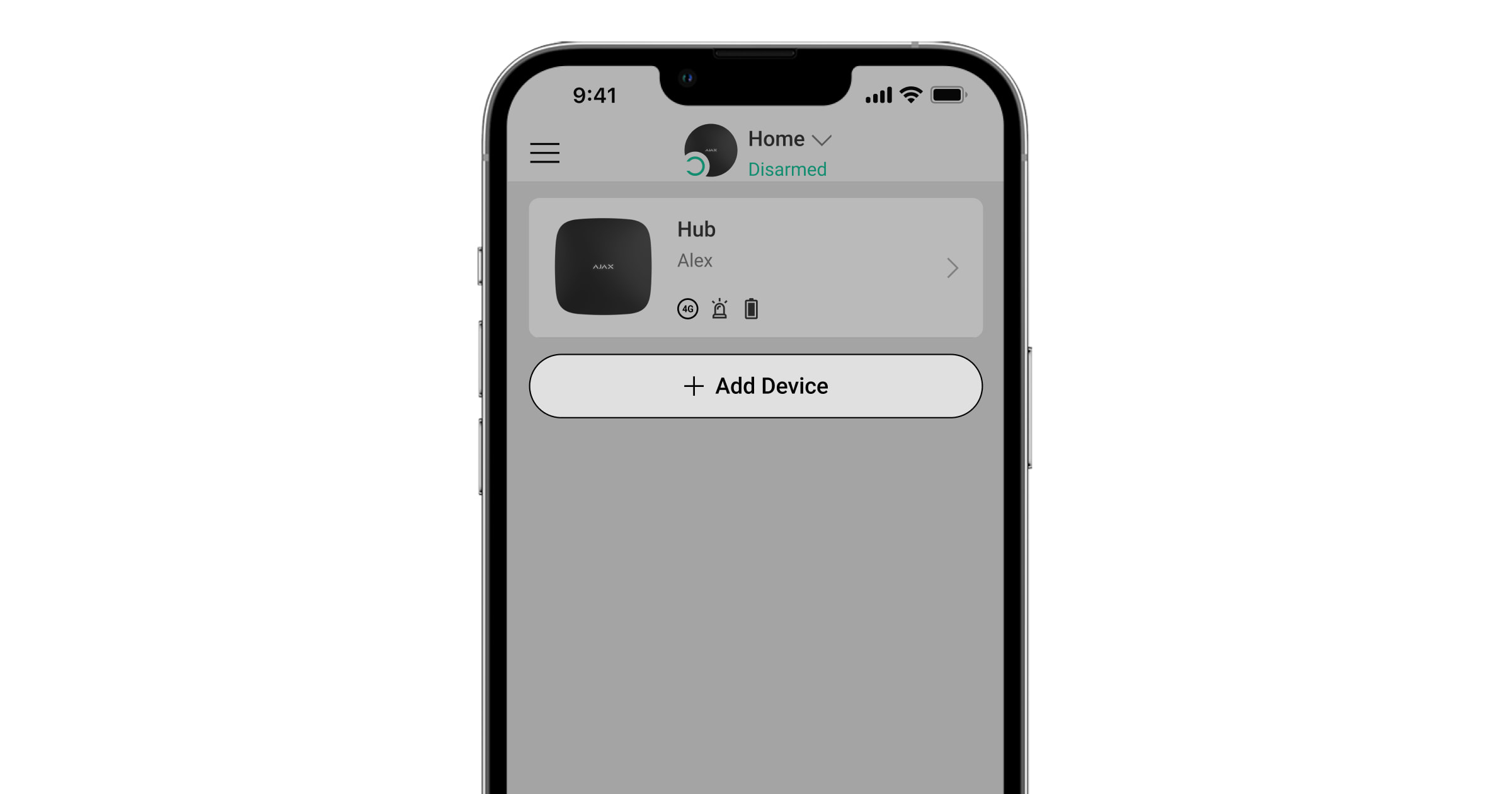
During the first hub registration in the app, you will be prompted to add devices to protect the room. However, you can refuse and return to this step later.
An admin or PRO with the rights to configure the system can add the device only when the system is disarmed.
- Open the Ajax app. Select the hub if you have several of them or if you are using a PRO Ajax app.
- Go to the Rooms tab.
- Open the room and select the Add Device option.
- Name the device, scan the QR code (or enter the ID manually), select the room, and go to the next step.
- When the app starts searching and launches countdown, switch on the device: its LED will flash once. For detection and pairing to occur, the device should be located within the coverage area of the wireless network of the hub (at a single protected facility).
If the connection fails on the first try, switch off the device for 5 seconds and retry.
Hub settings reset
To reset the hub to the factory settings:
- Turn on the hub if it is off.
- Remove all users and installers from the hub.
- Hold the power button for 30 seconds, and the Ajax logo on the hub will start flashing red.
- Remove the hub from your account.
All the connected detectors, room settings, and user settings will be deleted. User profiles will remain connected to the system.
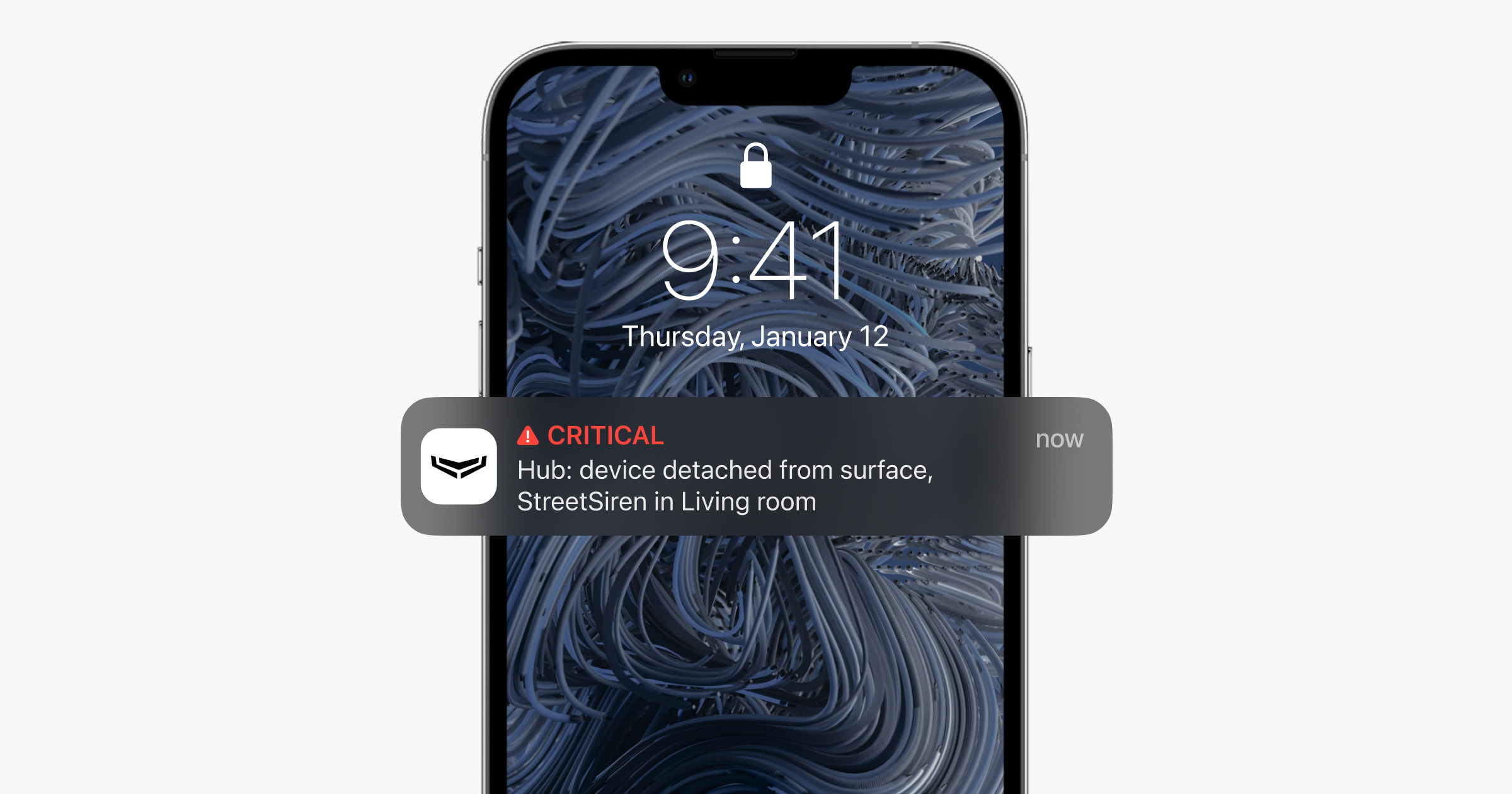
Events and alarm notifications
After adding the hub to the account, you become the admin of this device. Hub (2G) / (4G) Jeweller can have up to 50 system users, PRO users, and companies. The hub admin, PRO user with the rights to configure the system, or installation company can invite users to the system and determine their rights.
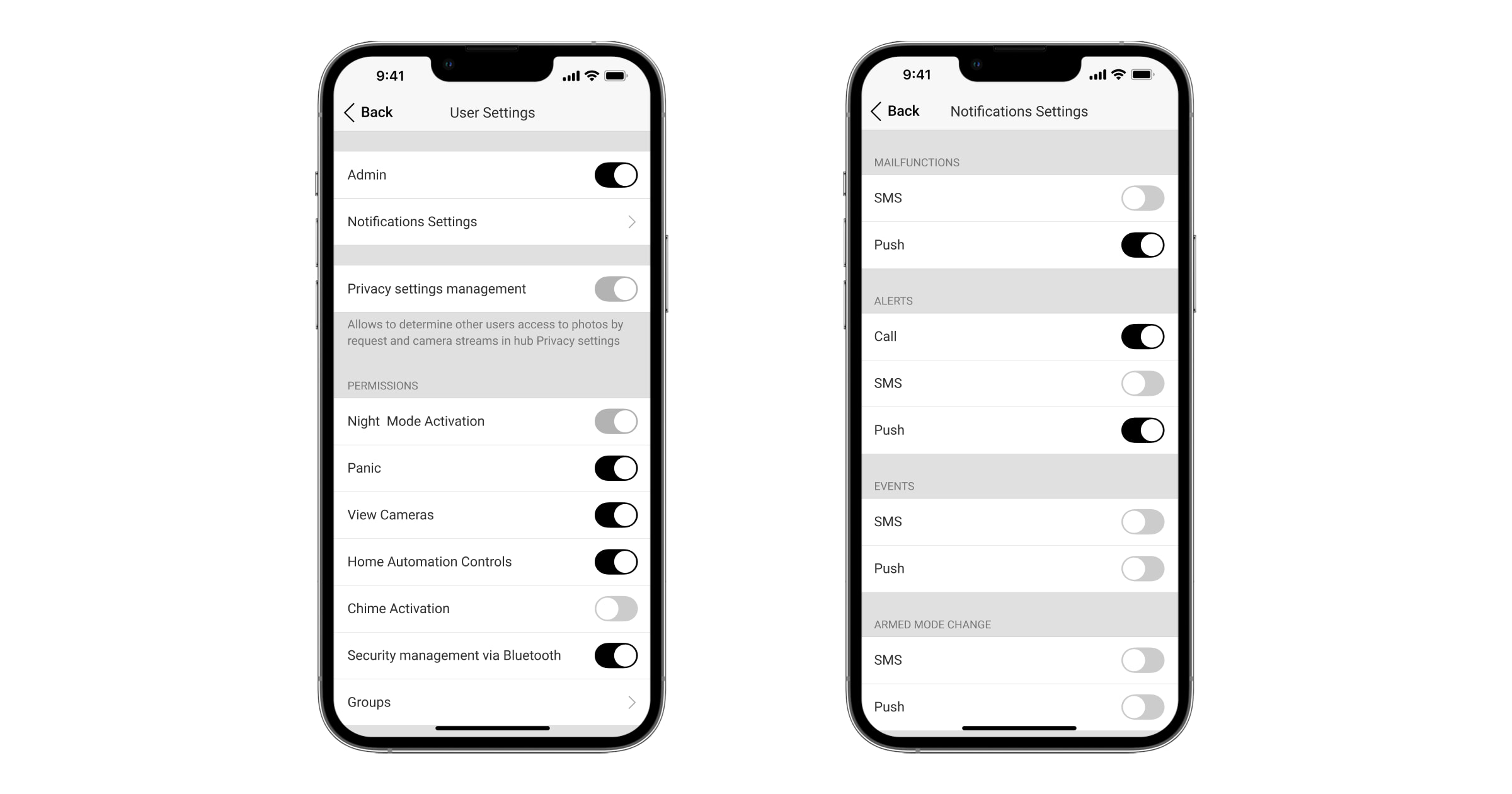
The hub notifies users of events in two ways: push notifications and SMS.
| Event types | For what it is used | Types of notifications |
| Malfunctions |
|
|
| Alarm |
|
|
| Events |
|
|
| Arming/Disarming |
|
|
When the Chime feature is enabled and configured, the hub does not notify users of opening detectors triggering in the Disarmed mode. Only the sirens connected to the system notify about the opening.
Connecting to the monitoring station of the security company
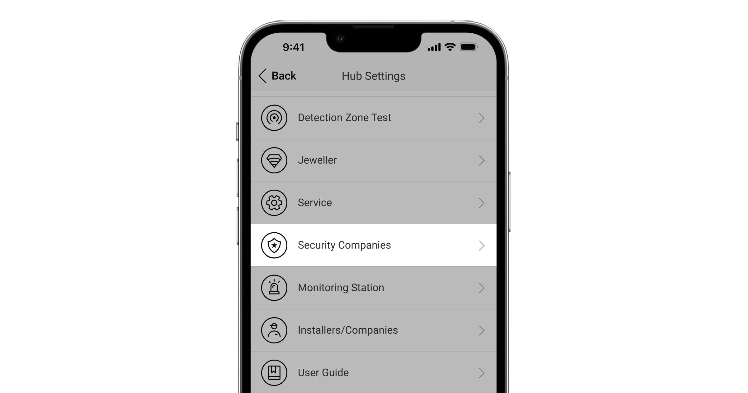
The list of companies connecting the Ajax system to the CMS is provided in the Security Companies menu of the hub settings.
Contact the company’s representatives providing services in your city and negotiate the connection.
Connection to the CMS is possible via the SurGard (Contact ID), ADEMCO 685, SIA DC-09 (SIA-DCS), and other proprietary protocols. A complete list of supported protocols is available here.
Maintenance
Check the operational capability of the Ajax system regularly. The optimal frequency of checks is once every three months. Clean the hub enclosure from dust, cobwebs, and other contaminants as they emerge. Use a soft and dry cloth that is suitable for equipment care.
Do not use any substances containing alcohol, acetone, petrol, or other active solvents for cleaning the hub.
If the hub battery becomes faulty, and you need to replace it, use the following guidance:
Complete set
- Hub (2G) Jeweller or Hub (4G) Jeweller.
- The SmartBracket mounting panel.
- Power supply cable.
- Ethernet cable.
- Installation kit.
- GSM start package or Ajax SIM (not available in all countries).
- Quick start guide.
Technical Specifications
Warranty
Warranty for the Limited Liability Company “Ajax Systems Manufacturing” products is valid for 2 years after the purchase.
If the device does not function properly, we recommend contacting the support service first, as technical issues can be resolved remotely in half of the cases.
Contact Technical Support: