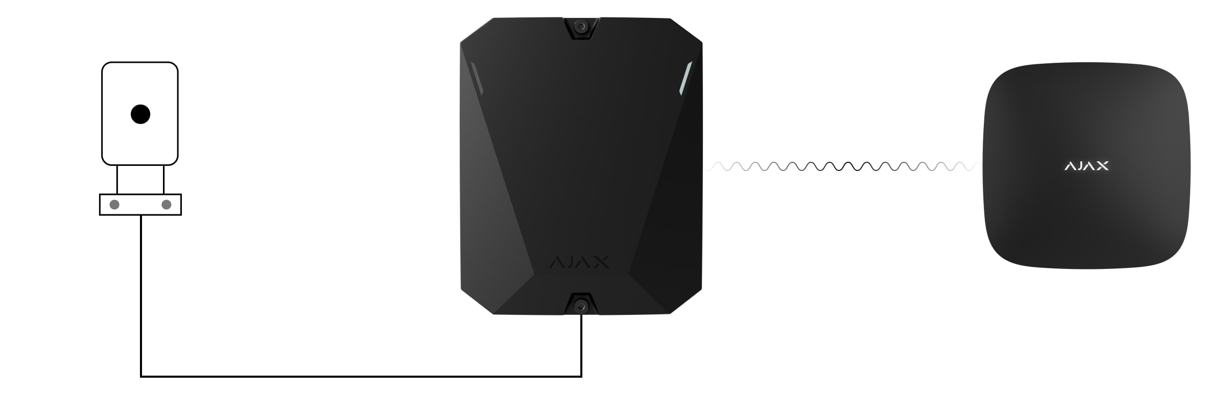
MultiTransmitter Jeweller is an integration module for connecting third-party wired detectors and devices to an Ajax security system. It has 18 wired zones for connecting NC, NO, EOL, 2EOL, and 3EOL devices.
MultiTransmitter is equipped with two tampers that protect it against dismantling. The device is powered from the 100–240 V~ mains, and can also run on a 12 V⎓ backup battery. Can supply 10.5–15 V⎓ for connected detectors and devices.
2EOL and 3EOL connections are only available for MultiTransmitter with firmware version 2.13.0 and higher. The integration module should be connected to Hub Plus*, Hub 2 (2G)*, Hub 2 (4G), Hub 2 Plus, Hub Hybrid (2G)* or Hub Hybrid (4G)* with the OS Malevich 2.13 firmware version and higher.
MultiTransmitter is incompatible with ocBridge Plus**, uartBridge** and third-party security control panels. 2EOL and 3EOL connections are unavailable for MultiTransmitter connected to Hub*.
We are stopping production and delivery of the previous version of MultiTransmitter without 2EOL and 3EOL support. Technical support and warranty services for these devices remain unchanged. So that users and partners can distinguish the versions from each other, the new devices come in different packaging — with a “3EOL” label.
Due to hardware differences, a firmware upgrade for old versions of MultiTransmitter is not provided.
* Only Hub 2 Plus Jeweller and Hub 2 (4G) Jeweller are certified according to UL/ULC standards.
** Not evaluated by UL.
MultiTransmitter works as a part of an Ajax security system and communicates with the hub via secure Jeweller radio protocol. The communication range with the hub is up to 2,000 meters in an open space.
Functional elements
Casing elements
- Screws fixing the casing lid. Use a hex key (Ø 4 mm) from the installation kit to unscrew it.
- Light guides for the integration module status indication (available in the new casing version, while the previous version features the LED indicator on the board).
- The place for installing the 12 V⎓ backup battery with a capacity of up to 7 A∙h.

The battery is not included in the MultiTransmitter complete set.
- MultiTransmitter QR code and ID / serial number.
- Perforated part of the casing. Necessary for tamper triggering in case of any attempt to detach the device from the surface. Do not break it off.
- Perforated parts of the casing for cable output.
- Fasteners for securing cables.
MultiTransmitter board elements
- 10.5–15.0 V⎓ power supply for fire detectors.
- MultiTransmitter 100–240 V~ power supply input.
- The first tamper button. Triggers in case of any attempt to remove the MultiTransmitter casing lid.
- Terminals for connecting a 12 V⎓ backup battery.
- Power button.
- LED indicator.
- MultiTransmitter QR code and ID / serial number.
- Terminals for connecting wired detectors and devices (zones).
- The second tamper button. Triggers in case of any attempt to detach the MultiTransmitter casing from the surface.
MultiTransmitter terminals
Terminals at the left side of the board:
GND — ground.
+EXT — 10,5–15 V⎓ power output for fire detectors, up to 1 A in total for all power outputs.
COM — common input for connecting power supply circuits and signal contacts of wired detectors and devices.
Terminals at the right side of the board:
Z1–Z18 — inputs for connecting wired detectors and devices.
+12V — 10,5–15 V⎓ power output for wired detectors and devices, up to 1 A in total for all power supply outputs.
COM — common input for connecting power supply circuits and signal contacts of wired detectors and devices.
Operating principle
MultiTransmitter is designed to integrate third-party wired detectors and devices to an Ajax security system. The integration module receives information about alarms, events, and malfunctions from detectors and devices via a wired connection. Then the integration module transmits the event to the hub using the Jeweller wireless communication protocol. The hub sends notifications to users and the security company’s Central Monitoring Station (CMS).
MultiTransmitter can be used to connect alarm and auxiliary request buttons, indoor and outdoor motion detectors, as well as detectors that track opening, vibration, glass breaking, fire, gas and water leakage, etc.
Also, you can set up KeyArm Zone that allows switching system arming modes with a third-party device connected to MultiTransmitter. KeyArm allows you to arm/disarm the system, individual groups, or manage Night Mode.
The KeyArm feature is supported by all hubs (except Hub model) with OS Malevich 2.17 and higher.
The device type is indicated in the zone settings to which the wired detector or device is connected. The selected type determines the text of notifications about alarms and events of the connected device, as well as event codes transmitted to the CMS.
Event types of wired devices
| Type | Icon | Meaning |
| Tamper alarm |
 |
Event of a detector or device tamper triggering. |
| Intrusion |
 |
Alarm when the motion, opening or other detector triggers. |
| Fire |
 |
Alarm when fire detectors trigger. |
| Auxiliary alarm |
 |
Alarm caused by pressing an auxiliary request button. |
| Panic button |
 |
Alarm caused by pressing an alarm button. |
| Gas alarm |
 |
Alarm when gas concentration is exceeded. |
| Malfunction |
 |
Event of a connected detector or device malfunction. MultiTransmitter should be connected to Hub Plus, Hub 2 (2G), Hub 2 (4G), Hub 2 Plus, Hub Hybrid (2G) or Hub Hybrid (4G) with the OS Malevich 2.13 firmware version and higher. |
| Leakage |
 |
Alarm caused by flooding. |
| Glass break |
 |
Alarm when the glass break sensor is triggered. This event type operates only in Pulse operating mode. |
| High temperature |
 |
Alarm when the upper temperature limit is exceeded. |
| Low temperature |
 |
Alarm when the lower temperature limit is exceeded. |
| Masking |
 |
Alarm when the device masking is detected. |
| Duress code (opening) |
 |
Alarm when the duress code is entered. This event type operates only in Pulse operating mode. |
| Vibration (seismic sensor) |
 |
Alarm when the seismic sensor is triggered. This event type operates only in Pulse operating mode. |
| Custom |
 |
The event type is customized by the user. Not sent to the security company monitoring station, and to users via SMS. MultiTransmitter should be connected to Hub Plus, Hub 2 (2G), Hub 2 (4G), Hub 2 Plus, Hub Hybrid (2G) or Hub Hybrid (4G) with the OS Malevich 2.13 firmware version and higher. |
MultiTransmitter has 18 wired zones. It is recommended to connect one device to one zone. The number of connected devices depends on their power consumption. The maximum consumption of all devices or detectors connected to all zones is 1 A.
The integration module has three 10.5–15 V⎓ power supply lines: one for fire detectors and two for other devices.
After the fire alarm, fire detectors need a power reset to restore normal operation. Therefore, the power supply of fire detectors should only be connected to a dedicated line. Also, avoid connecting other detectors and devices to the fire detectors power supply terminals as this may lead to false alarms or incorrect operation of the devices.
Supported connection types:
- NO (normally open).
- NC (normally closed).
- EOL (connection with one resistor).
- 2EOL (connection with two resistors).
- 3EOL (connection with three resistors).
The device supports EOL with resistance from 1 to 15 kΩ, the total resistance of all resistors is up to 30 kΩ. To increase the protection against sabotage, EOL resistors with different resistance can be used in one detector. Recommendation resistance ratio of EOL resistors: R1=R, R2=2·R, R3=3·R.
In the Ajax app, you can select the normal state (normally closed or normally open) for each of the terminal pairs: alarm, tamper, and malfunction. This allows connecting any potential-free contact detector of any configuration to MultiTransmitter.
2EOL and 3EOL connections are only available for MultiTransmitter with firmware version 2.13.0 and higher. The integration module should be connected to Hub Plus, Hub 2 (2G), Hub 2 (4G), Hub 2 Plus, Hub Hybrid (2G), or Hub Hybrid (4G) with the OS Malevich 2.13 firmware version and higher.
Jeweller radio communication technology
Jeweller is a radio protocol that provides fast and reliable two-way communication between the hub and the devices of the system. Protocol instantly sends informative alarm notifications: security companies and users know exactly which one device triggered, when and where it happened.
Jeweller supports encryption and authentication to prevent sabotage, and regular polls to display device status in real-time. Jeweller supports up to 2,000 m of wireless connectivity, providing the facilities protection and the best user experience for both system owners and installers.
Transmitting events to the monitoring station
The Ajax security system can transmit events and alarms to the Ajax PRO Desktop monitoring app, as well as to the Central Monitoring Station (CMS) in SurGard (Contact ID), SIA (DC-09), ADEMCO 685, and other proprietary protocol formats. A complete list of supported protocols is available here.
MultiTransmitter can transmit the following events:
- MultiTransmitter tampers alarm / restoration.
- Connected devices alarm / restoration.
- Loss / restoration of connection between MultiTransmitter and the hub / radio signal range extender.
- Loss / restoration of connection between MultiTransmitter and the devices connected to it.
- Deactivation / activation of MultiTransmitter.
- Deactivation / activation of wired detectors and devices connected to MultiTransmitter.
- Unsuccessful attempt to arm the security system (if system integrity check is enabled).
In the event of an alarm, the monitoring station operator of the security company knows what happened and where the rapid response unit has to be sent. All Ajax devices are addressable, so events, the device type, its assigned name and room can be transmitted to PRO Desktop and the CMS. The list of transmittable parameters may differ depending on the CMS type and the selected communication protocol with the monitoring station.
Find the ID and loop (zone) number of the integration module and connected wired devices in Ajax app. To do this, open the States of the integration module or the connected device. The device number corresponds to the loop (zone) number.
Adding MultiTransmitter to the system
Wired detectors can be connected to MultiTransmitter both before adding the module to the hub and after that.
Before adding a device
- Install the Ajax app.
- Log in to your account or create a new one.
- Select a space or create a new one.
The space functionality is available for apps of such versions or later:
- Ajax Security System 3.0 for iOS;
- Ajax Security System 3.0 for Android;
- Ajax PRO: Tool for Engineers 2.0 for iOS;
- Ajax PRO: Tool for Engineers 2.0 for Android;
- Ajax PRO Desktop 4.0 for macOS;
- Ajax PRO Desktop 4.0 for Windows.
- Add at least one virtual room.
- Add a compatible hub to the space. Ensure the hub is switched on and has internet access via Ethernet, Wi-Fi, and/or mobile network.
- Ensure the space is disarmed, and the hub is not starting an update by checking statuses in the Ajax app.
Only a PRO or a space admin with the rights to configure the system can add a device to the hub.
How to add MultiTransmitter
- Connect the power cable to the appropriate connector.
To comply with the INCERT requirements, use the Screw terminal block Adapter to connect the external power supply. Read more.
- Open the Ajax app. Go to the Devices tab and press Add device.
- Name the integration module.
- Scan QR code or type the device ID. You can find the QR code on the back of the casing, on the board and packaging of the device. The device ID is below the QR code.
- Choose a virtual room and group (if the Group mode is enabled).
- Click Add.
- Enable the MultiTransmitter by pressing the power button for 3 seconds. Note that a request to connect to the hub is sent at the very moment the integration module is turning on. If the connection fails, turn off MultiTransmitter for 5 seconds and try again.
To pair with the hub, the integration module should be located within a range of the hub radio communication (at the same secure facility).
If the maximum number of devices has already been added to the hub, you will receive an error notification when adding.
MultiTransmitter works with one hub only. After connecting to the new hub, the integration module stops exchanging commands with the previous one. When added to a new hub, MultiTransmitter is not removed from the previous hub list of devices. Remove it via the Ajax app.
The connected integration module appears in the hub device list in the app. Device status updating depends on the polling interval adjusted in the Jeweller or Jeweller/Fibra settings (36 seconds by default).
MultiTransmitter icons
The icons provide info on some MultiTransmitter states. Check them in the Devices ![]() tab of the app.
tab of the app.
| Icon | Meaning |
|
Jeweller signal strength between the hub/range extender and MultiTransmitter. Recommended values: 2 or 3 bars. |
|
| The fire detector connected to MultiTransmitter has registered an alarm. | |
|
The charge level of the MultiTransmitter backup battery. |
|
| MultiTransmitter has a malfunction. A list of faults is available in the integration module states. | |
| MultiTransmitter run via radio signal range extender. | |
|
MultiTransmitter is temporarily disabled. |
|
|
MultiTransmitter has tamper triggering events temporarily disabled. |
|
|
The device was not transferred to the new hub. |
MultiTransmitter states
The states provide info on the integration module and its operating parameters. Check the MultiTransmitter states in the Ajax app:
- Go to the Devices tab.
- Select MultiTransmitter from the device list.
| Parameter | Meaning |
| Malfunction |
Pressing The field is displayed only when malfunction is detected. |
| Jeweller Signal Strength |
Signal strength between hub/radio signal range extender and MultiTransmitter. We recommend installing the integration module in places with the signal strength of 2-3 bars. |
| Connection via Jeweller | Connection status between hub/range extender and MultiTransmitter:
|
| Name of the ReX range extender | The field is displayed when the device is running via radio signal range extender |
| Battery Charge |
The charge level of the connected battery. Displayed as a percentage with 5% increments. |
| Lid | The status of tampers that trigger if someone tries to detach the casing from the surface or violate the casing integrity:
|
| External Power | The external power supply 100–240 V~ is:
|
| Detectors Power Line | The status of detector power terminals:
|
| Fire Detector Power Line | The status of power supply terminals of fire detectors:
|
| Deactivation | Shows the status of the temporary device deactivation function:
|
| Firmware | MultiTransmitter firmware version. |
| Device ID |
MultiTransmitter ID/serial number. Also is available below the QR code on the back of the casing, on the board and on the integration module packaging. |
| Device № | MultiTransmitter loop (zone) number. |
MultiTransmitter settings
To change the MultiTransmitter settings in the Ajax app:
- Go to the Devices tab.
- Select MultiTransmitter in the list.
- Go to Settings by clicking on the gear icon .
- Configure the parameters.
- Click Back to save the new settings.
| Setting | Meaning |
| Name |
Integration module name. Displayed in the hub device list, the text of SMS, and event feed notifications. To change the name of the module, click on the text field. The name can contain up to 12 Cyrillic characters or up to 24 Latin symbols. |
| Room |
Selecting the virtual room to assign MultiTransmitter. The room name is displayed in the text of SMS and event feed notifications. |
| Alert with a siren if power supply for detectors is shorted out | When this option is enabled, the sirens connected to the security system activate in case the power supply line for detectors is shorted out. |
| Jeweller Signal Strength Test |
Activates the Jeweller Signal Strength Test mode of MultiTransmitter. The test allows checking the signal strength between the hub and MultiTransmitter and choosing the optimal spot to install the device. |
| Signal Attenuation Test |
Activates the Signal Attenuation Test mode of MultiTransmitter. |
| User Guide | Opens the MultiTransmitter User Manual in the Ajax app. |
| Permanent Deactivation |
Allows the user to deactivate the device without removing it from the system. Two options are available:
Learn more about permanent device deactivation The system will only ignore notifications about the triggering of the device tamper button. Detectors and devices connected via MultiTransmitter will continue operating normally. The system can also automatically deactivate devices when the specified number of alarms is exceeded or when the restoration timer expires. |
| Unpair Device | Unpairs MultiTransmitter from the hub and deletes its settings. |
MultiTransmitter malfunctions
If the MultiTransmitter malfunction is detected (e. g., loss of connection with the hub via Jeweller), the Ajax app displays a malfunction counter in the upper left corner of the device icon.
All faults can be seen in the integration module states. Fields with malfunctions will be highlighted in red.
The malfunction is displayed if:
- The integration module casing is open or dismantled from the surface (tamper alarms).
- There is no connection between the integration module and the hub/radio signal range extender via Jeweller.
- The battery is discharged.
- The battery charges for more than 40 hours.
- Failed to connect a backup battery (the battery is not connected or there are hardware problems, such as a faulty connection cable).
- The detector power supply line is shorted out.
MultiTransmitter can report malfunctions to the security company monitoring station, as well as to users via push notifications and SMS.
MultiTransmitter placement

When choosing the place to install MultiTransmitter, consider the parameters affecting the correct operation of the integration module:
- Jeweller signal strength.
- Distance from the hub.
- Presence of obstacles for the passage of the radio signal between integration module and hub: walls, floors, dimensional objects.
- Cable length for connecting wired detectors and devices to MultiTransmitter.
Consider placement guidelines when designing your security system. The design and installation of the security system should be carried out by professionals. The list of authorized Ajax partners is available here.
Signal strength
The Jeweller signal strength is determined by the number of undelivered or damaged data packets exchanged between the hub and the detector during a certain time. The signal strength is indicated by the ![]() icon in the Devices
icon in the Devices ![]() tab:
tab:
- Three bars — excellent signal strength.
- Two bars — good signal strength.
- One bar — low signal strength, the stable operation is not guaranteed.
- Crossed out icon — no signal.
Check the Jeweller signal strength at the installation location. With a low signal strength (one or zero bars), we do not guarantee stable operation of the security system. In this case, we recommend moving the device as changing the position even by 20 centimeters can significantly improve the quality of radio communication. If the integration module still has a low or unstable signal strength after moving, use a radio signal range extender.
Do not install MultiTransmitter
- Outdoors. This may lead to integration module failure.
- Inside any premises with the temperature and humidity parameters that do not correspond to the device operating range. This may lead to integration module failure.
- In locations where the integration module has a Jeweller signal strength of zero or one bar. This could result in the loss of connection with the integration module.
- At a distance of less than one meter from the hub or radio signal range extender. This could result in the loss of connection with the integration module.
Installing MultiTransmitter
Before installing MultiTransmitter, make sure that you have chosen the optimal location and that it meets the conditions of this manual. Run the Jeweller Signal Strength Test before final installation.
MultiTransmitter is designed for indoor installation. We recommend choosing the installation location hidden from eyes.
Fix the integration module on a vertical surface with the fasteners from the installation kit. All the necessary holes are already made.
Vertical fixation of the integration module is needed for the tamper to respond if someone tries to detach a device. Learn the battery documentation before installing — some batteries can be mounted only vertically (with terminals upward). Another installation position could cause fast battery degradation.
To install the module:
- Prepare the cable outputs in advance by carefully breaking out the perforated parts of the MultiTransmitter casing.
- Secure the casing on the vertical surface at the selected installation location with the bundled screws using all fixation points. One of them is in the perforated part above the tamper — it is required for tamper triggering in case of any attempt to detach the MultiTransmitter casing.
- Install the MultiTransmitter board into the casing on the holders.
- Install a 12 V⎓ backup battery at the special fixation racks in the casing. Note that third-party power supply units cannot be connected to the terminals.
We recommend using a 12 V⎓ battery with a capacity of 4 or 7 A∙h. For such batteries there are special racks in the casing. You can also use similar batteries of a different capacity if their size fits the casing, and the maximum full charge time doesn’t exceed 30 hours. The maximum battery dimensions for installing in the casing are 150 × 65 × 94 mm, and the maximum weight is 5 kg.
- Connect wired detectors and devices to the integration module.
- Connect the backup battery to the board terminals according to the diagram below using the connection cable from the complete set. Observe the polarity of wire connection. Securely fasten the wires in the terminals.
- Turn on the integration module.
- Install the lid on the integration module casing and secure it in the lower and upper parts of the casing using the screws from the installation kit.
Connecting wired detectors and devices to MultiTransmitter
Preparation and cable length
Carefully read the user manual for the third-party wired detector or device before connecting it to MultiTransmitter. If you have any questions, please contact the technical support of the detector or device manufacturer.
Violation of the basic installation rules, the recommendations of this manual and the instructions of the manufacturers of third-party wired detectors or devices can lead to their incorrect operation and false alarms.
When planning where to install the integration module or connected wired devices, consider the wiring diagram of the power cables at the facility. Signal cables for security system devices must be laid at a distance of at least 50 cm from the power cables in case of parallel routing. If cables intersect, keep the 90° angle.
For facilities that are under construction or renovation, cables are laid after the facility electrical wiring is installed. Use protective tubes, ties, clips, and staples to organize and secure the cables. Make sure that the fasteners do not damage the cables or their insulation during installation.
When laying cables externally (without mounting them inside the walls), use an electric channel raceway. Raceways should be no more than half-filled with cables. Do not allow cables to sag. The raceway should be hidden from view if possible — for example, behind furniture.
We recommend laying cables inside the walls, floors, and ceilings. This will provide greater security: the cables will not be visible, and it will be impossible for an intruder to access them.
When installing, observe the bend radius that the manufacturer specifies in the cable specs. Otherwise, you risk damaging or breaking it.
Before installation, check all cables for bends and physical damage. Perform the installation in a way that minimizes the possibility of damage to the cables from the outside.
We recommend using signal copper-plated aluminum cable with a 0.22 mm² cross-section. The maximum length of the signal cable used to connect third-party devices to MultiTransmitter is 400 meters . The value may vary if a different type of cable is used. No other types of cables have been tested.
Connecting to MultiTransmitter
When connecting to the integration module, do not twist the wires together; solder them. The ends of the wires which will be connected into the integration module terminals should be tinned or crimped with a special sleeve. This will ensure a reliable connection. Follow safety precautions and electrical installation rules when connecting the integration module and third-party detectors and devices.
- Select the MultiTransmitter zone to connect a detector or device.
- Route the cable into the integration module casing.
- Connect third-party wired detectors or devices to the appropriate MultiTransmitter terminals. The wiring diagram can be found in the user manual provided by the manufacturer of the wired device.
Carefully read the manufacturer’s instructions before connecting the device to MultiTransmitter.
- Securely fasten the wires in the terminals.
- Fix the cable with ties using special fasteners inside the casing.
If the wired detector or device requires a 12 V⎓ power supply, it can be connected to the power terminals of the corresponding MultiTransmitter zone. Separate terminals are provided for fire detectors. Do not connect external power supply (such as third-party power supply units) to the detector power terminals, as this may damage the device.
- Add a detector or device to the system.
Adding to the system
In the Ajax security system, each device or detector connected to MultiTransmitter takes one slot within the hub device limit.
- Open the Ajax app. Go to the Devices tab.
- Find MultiTransmitter in the device list.
- Click the Devices menu under the integration module icon.
- Click Add Wired Device.
- Name the device or detector, select the wired zone, to which the device or detector will be connected, select the virtual room and the group.
- Click Add. The device or detector will be then added within 30 seconds. If the connection fails – check that the wired connection is correct and try again.
Icons of connected detectors and devices
The icons display some states of the devices connected to MultiTransmitter. Check them in the Ajax app in the Devices ![]() tab.
tab.
| Icon | Meaning |
| Chimes function is activated. | |
|
|
Delay When Entering and / or Leaving is enabled. |
| The device operates in Always active mode. | |
| The device will operate when Night Mode is enabled. | |
|
Device status is OK. Displays only for EOL, NC, and NO connections. |
|
|
The device is shorted out. Displays only for EOL, NC, and NO connections. |
|
| The device tamper state is OK.* | |
| Device tamper alarm.* | |
| Status of intrusion sensors is OK.* | |
| Intrusion alarm.* | |
| The auxiliary request button state is OK.* | |
| Alarm when pressing the auxiliary request button.* | |
| The alarm button state is OK.* | |
| Alarm when pressing the alarm button.* | |
| Fire sensor state is OK.* | |
| The device detected a fire alarm.* | |
| The gas sensor state is OK.* | |
| Alarm when gas concentration is exceeded.* | |
| Device status is OK.* | |
| Device malfunction is detected.* | |
| The flood sensor state is OK.* | |
| Alarm caused by flooding.* | |
| The state of the glass break sensor is OK.* | |
| Glass break alarm.* | |
| The state of the high temperature sensor is OK.* | |
| Alarm when the upper temperature limit is exceeded.* | |
| The state of the low temperature sensor is OK.* | |
| Alarm when the lower temperature limit is exceeded.* | |
| The state of the masking sensor is OK.* | |
| Masking alarm.* | |
| The state of the duress code device is OK.* | |
| Alarm triggered when the system is disarmed using the duress code.* | |
| The state of the vibration (seismic) sensor is OK.* | |
| Vibration (seismic) alarm.* | |
| The status of the device for which the custom type of event is selected is OK.* | |
| The alarm caused by the device for which the custom type of event is selected.* | |
| The device is automatically disabled due to exceeding the number of alarms. | |
| The device is automatically disabled by the restoration timer. | |
| Device is temporarily disabled by the system user. |
* Icon is displayed for 2EOL and 3EOL connections only.
States of connected detectors and devices
The states provide info on the device and its operating parameters. Check the states of the detectors and devices connected to MultiTransmitter in the Ajax app:
- Go to the Devices tab.
- Select MultiTransmitter in the list.
- Click Devices under the MultiTransmitter icon.
- Select the device from the list.
| Parameter | Meaning |
| Malfunction |
Clicking The field is displayed if a malfunction is detected. |
| MultiTransmitter name | State of MultiTransmitter to which the wired device is connected:
|
|
Device State Displayed for Without EOL and EOL input types |
Status of connected wired device:
|
|
Tamper sensor Displayed for 2EOL and 3EOL input types |
The tamper status of the connected device:
|
|
“Name of the selected event type” sensor Displayed for 2EOL and 3EOL input types |
Status of connected wired device:
|
| Always Active |
If the option is enabled, the device connected via MultiTransmitter is constantly armed and notifies of alarms. This option can only be configured for certain event types. |
|
Device resistance Displayed for EOL, 2EOL, and 3EOL input types |
The total resistance of the resistor(s) connected to the device is measured automatically. The value can also be set manually with 100 Ω increments. |
| Permanent Deactivation | Shows the status of the permanent device deactivation function:
The user can also separately configure device deactivation:
The option is configured in the Ajax PRO app. |
| Alarm Reaction | |
| Operating Mode | Shows how the detector reacts to alarms:
|
| Delay When Entering, sec |
Delay time when entering is 5 to 120 seconds. Delay when entering (alarm activation delay) is the time the user has to disarm the security system after entering the secure zone. |
| Delay When Leaving, sec |
Delay time when leaving is 5 to 120 seconds. Delay when leaving (alarm activation delay) is the time the user has to leave the secure zone after arming the system. |
| Night Mode Delay When Entering, sec |
Night Mode Delay When Entering is 5 to 120 seconds. Delay when entering (alarm activation delay) is the time the user has to disarm the security system after entering the premises. |
| Night Mode Delay When Leaving, sec |
Night Mode Delay When Leaving is 5 to 120 seconds. Delay when leaving (alarm activation delay) is the time the user has to exit the premises after enabling the arming mode. |
| Wired device № | The number of the MultiTransmitter zone to which the wired detector/device is connected. |
| Device № | Device loop (zone) number. |
Configuring connected detectors and devices
To change the settings of a connected device, in the Ajax app:
- Go to the Devices tab.
- Select MultiTransmitter in the list.
- Click Devices under the MultiTransmitter icon.
- Select the device from the list.
- Go to Settings by clicking on the gear icon .
- Set the required parameters.
- Click Back to save the new settings.
| Settings | Meaning |
| Name |
Wired device name. Displayed in the hub device list, the text of SMS and event feed notifications. To change the name, click on the text field. The name can contain up to 12 Cyrillic characters or up to 24 Latin symbols. |
| Room |
Virtual room to which a device is assigned. The room name is displayed in the text of SMS and event feed notifications. |
| Input Type | Selecting the connection type for a third-party device:
2EOL and 3EOL connections are only available for MultiTransmitter with firmware version 2.13.0 and higher. The integration module should be added to Hub Plus, Hub 2 (2G), Hub 2 (4G), Hub 2 Plus, Hub Hybrid (2G), or Hub Hybrid (4G) with OS Malevich 2.13 firmware version and higher. |
| Default State | Selecting the normal state of the contact of the connected device:
|
| Sensor Mode | Selecting the sensor mode of the connected device:
|
| Arm Switch Settings | Configuring the arm switch if the Switch Arming Modes option is selected for the Sensor Mode setting:
|
| Type of Event |
Selecting an event type for the connected device. Refer to the Event types of wired devices section for more information. The selected type of event defines the text of notifications in the event feed and SMS, as well as the alarm code transmitted to the security company monitoring station. This setting is available if Notify of Alarms option is selected for the Sensor Mode setting. |
| Operating Mode | Operating mode of the connected device:
Make sure to set the type matching the connected detector. The pulse detector in the bistable mode generates unnecessary restoration notifications. A bistable detector in the pulse mode, on the contrary, will not send restoration notifications. |
| Always Active |
When the option is enabled, the detector connected via MultiTransmitter is constantly armed and notifies of alarms. This option can only be configured for certain event types. This setting is available if Notify of Alarms option is selected for the Sensor Mode setting. |
| Pulse Time | The pulse time of a device for detecting an alarm:
An alarm will be raised if the pulse from the detector lasts longer than specified in this setting. Can be used as a false alarm filter. |
| Alert with a siren if alarm is detected | If the function is enabled, connected to the system sirens will be activated when an alarm is detected. |
| Chime Settings |
Opens the Chime Settings. This function is available for bistable detectors only. |
| Alarm Reaction | |
| Operating Mode | Specify how this device will react to alarms:
|
| Delay When Entering, sec |
Delay time when entering is 5 to 120 seconds. Delay when entering (alarm activation delay) is the time the user has to disarm the security system after entering the secure zone. |
| Delay When Leaving, sec |
Delay time when leaving is 5 to 120 seconds. Delay when leaving (alarm activation delay) is the time the user has to leave the secure zone after arming the system. |
| Arm in Night Mode |
If the option is enabled, the detector connected to the integration module will switch to the armed mode if the system is set to Night Mode. |
| Night Mode Delay When Entering, sec |
Night Mode Delay When Entering is 5 to 120 seconds. Delay when entering (alarm activation delay) is the time the user has to disarm the security system after entering the premises. |
| Night Mode Delay When Leaving, sec |
Night Mode Delay When Leaving is 5 to 120 seconds. Delay when leaving (alarm activation delay) is the time the user has to exit the premises after enabling the arming mode. |
| Permanent Deactivation |
Allows deactivating the device without removing it from the system. Two options are available:
The user can also separately configure device deactivation:
The option is configured in the Ajax PRO app. |
How to configure Chime
The Chime is an audio signal notifying about the opening detectors triggering when the system is disarmed. The feature is used, for example, in stores to notify employees that someone has entered the door.
The notification is set in two stages: configuring the opening detectors and configuring the sirens.
Configuring a wired opening detector connected to MultiTransmitter
Before setting up the Chime feature, make sure that a wired opening detector is connected to MultiTransmitter and the following options have been configured in the detector settings in the Ajax app:
- Type of Event — Intrusion.
- Operating Mode — Bistable.
- Always Active — disabled.
- Go to the Devices tab.
- Select MultiTransmitter in the list.
- Click Devices under the MultiTransmitter icon.
- Select the device from the list.
- Go to Settings by clicking on the gear icon .
- Go to the Chime menu.
- Select the siren notification of the event and press If device is triggered.
- Select the chime sound: 1 to 4 short beeps. Once selected, the Ajax app will play the sound.
- Click Back to save the settings.
- Set up the required siren.
Malfunctions of connected wired detectors and devices
If a malfunction is detected in a wired detector or device, the Ajax app displays a malfunction counter in the upper left corner of the device icon.
All malfunctions can be seen in the states of connected device. Fields with faults will be highlighted in red.
The malfunctions are displayed if:
- The enclosure of the device is open (tamper triggering).
- No connection between the integration module and the device (contacts are damaged).
- Incorrect connection of resistors (resistance of resistor error).
- The system has detected a short circuit in the device contacts.
The connected device can report malfunctions to the security company monitoring station, as well as to users via push notifications and SMS.
Fire alarms reset
In case of alarms of fire detectors connected to MultiTransmitter, the Ajax app displays the notifications prompting to reset the alarms. The reset returns the detectors to their normal state so they can continue detecting a fire.
If you do not reset the alarm after a fire alarm, the detectors will not respond to the next fire, as they will remain in alarm mode.
There are two ways to reset fire alarms:
- By clicking the button in the notification in the app.
- Via the MultiTransmitter menu: click the red button opposite the integration module.
MultiTransmitter indication
The MultiTransmitter LED indicator may light up in white, red, or green depending on the device status.
In the previous MultiTransmitter casing version, the LED indicator is not visible when the casing lid is closed. You can check the device status only in the Ajax app.
The new MultiTransmitter casing version features light guides, allowing the integration module state to be viewed at any time.
If MultiTransmitter is not added to the hub or has lost connection with it, the integration module will not indicate the battery status or the presence of external power.
| LED indication | Event | Note |
| Lights up in white. | Stable communication with the hub. The external power is connected. | |
| Lights up in red. | Communication with the hub is lost. External power is connected. | For example, the hub is disabled or the MultiTransmitter is out of the hub radio network coverage. |
| Goes out for 0.5 seconds, then lights up in green and turns off. | Disabling MultiTransmitter. | |
| Flashes red once per second. | MultiTransmitter is not added to the hub. | |
| Lights up once a second every 10 seconds. | MultiTransmitter has no external power supply. |
Lights up in white if MultiTransmitter has communication with the hub. Lights up in red if there is no communication with the hub. |
| In case of alarm, it lights up smoothly and goes out once every 10 seconds. | MultiTransmitter has no external power supply, and an external battery is discharged. |
Lights up in white if MultiTransmitter has communication with the hub. Lights up in red if there is no communication with the hub. |
MultiTransmitter functionality test
Ajax security system provides several tests to correctly select the location of devices. The MultiTransmitter tests do not begin immediately, but not later than over a single hub—detector polling interval (36 seconds by default hub settings). You can change the device polling interval in the Jeweller menu in the hub settings.
To start the test in the Ajax app:
- Select the hub.
- Go to the Devices tab.
- Select MultiTransmitter.
- Go to Settings .
- Select a test:
- Start and run the test.
Maintenance
Check the functionality of the integration module and the connected wired detectors and devices on a regular basis. The optimal interval for the check is once every three months. It is recommended to check that the wires are tightly fixed and connected to the terminals of the integration module.
Clean the casing from dust, cobwebs, and other contaminants as they emerge. Use a soft dry cloth that is suitable for equipment care. Do not use any substances containing alcohol, acetone, gasoline, and other active solvents to clean the device.
Technical specifications
Complete set
- MultiTransmitter Jeweller.
- Casing.
- Power supply cable.
- Screw terminal block Adapter (only for INCERT compliance).
- 12 V⎓ battery connection cable.
- Installation kit.
- Quick start guide.
Warranty
The warranty for the products of the Limited Liability Company “Ajax Systems Manufacturing” is valid for 2 years after purchase.
If the device does not operate properly, we recommend you contact support service first, as in most cases, technical issues can be resolved remotely.
Contact technical support:
Manufactured by “AS Manufacturing” LLC