Superior MegaHub (without casing) is a hybrid control panel for an Ajax system, designed as a board that can be installed into an Ajax casing and is compatible with both wired and wireless Ajax devices. It controls connected device operation and interacts with both users and the monitoring company. The control panel is also available in a standard casing. This version is called Superior MegaHub.
The hub requires internet access to connect to the Ajax Cloud server. Available communication channels are Ethernet, Wi-Fi, and two SIM cards. For cellular connection, Superior MegaHub (without casing) is equipped with a 2G/4G (LTE) modem.
Superior MegaHub (without casing) features a connector for attaching a tamper board when the hub is installed into a compatible Ajax casing. The tamper board protects the hub from dismantling. The device is powered by a 100–240 V~ mains and can also be powered by a 12 V⎓ backup battery. The hub has external antenna connectors for cellular, Jeweller, and Wings communication channels.
Superior MegaHub (without casing) is a device of the Superior product line. Only accredited Ajax Systems partners can sell, install, and maintain Superior products.
Functional elements
Board elements
- Connector for attaching the tamper board to the hub. The tamper board is included in the Ajax Case complete set, which is sold separately.
- LED indicator for displaying the states of the hub and connected communication channels.
- Power button.
- External antenna connector for the Wings communication channel (SMA female connector).
- Slot for micro SIM 1.
- Slot for micro SIM 2.
- QR code and ID (serial number) of the device.
- External antenna connector for the cellular communication channel (SMA female connector).
- External antenna connector for the Jeweller communication channel (SMA female connector).
- Connector for attaching the external LED to the hub. The external LED is included in the Superior MegaHub (without casing) complete set.
- Power cable terminals.
- Connector for connecting a 12 V backup battery.
- Fibra line terminals for connecting wired devices.
- Ethernet cable connector.
- Mounting holes for installing the Superior MegaHub (without casing) board into Ajax Case using three Module Holder (type A) holders.
Fibra line terminals
Superior MegaHub (without casing) has eight Fibra lines. Numbers 1 to 8 are indicated on the control panel board. Each Fibra line has its own LED indicator that shows its current state.
Fibra line terminals:
- +24 V — 24 V⎓ power supply terminal.
- A — first signal terminal.
- B — second signal terminal.
- GND — power ground terminal.
When installing Fibra devices, observe the polarity and wire connection order.
Operating principle
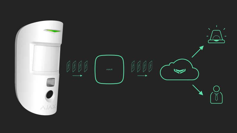
Superior MegaHub (without casing) is a hybrid control panel of an Ajax system. It controls the connected device operation. The hub is added to a space, a virtual entity where various autonomous devices are gathered on the same physical object.
You can add up to 999 wired and wireless Ajax devices to Superior MegaHub (without casing). Connected devices protect against intrusion, fire, and flooding. They also allow you to control electrical appliances according to scenarios or manually — in a mobile app, by pressing the panic button, by actuating LightSwitch, or via the keypad with touchscreen.
The hub supports both devices with the new firmware version (i.e., with the “999 ready” label) and devices with the legacy firmware version. However, no more than 250 devices with the legacy firmware can be added to the hub. The remaining devices within the 999 limit must have the new firmware version.
Superior MegaHub running OS Malevich 2.37 supports up to 250 Jeweller devices, including those with upgraded and legacy firmware. This is a temporary limitation that will be lifted in future updates.
To monitor the operation of all system devices, the hub uses encrypted protocols to communicate with them:
1. Superior Jeweller is a radio protocol for transmitting events and alarms from wireless Ajax devices. The communication range is up to 8,200 ft in open space.
2. Wings is a radio protocol for transmitting large data packets. The communication range is up to 8,200 ft in open space.
3. Fibra is a wired protocol for transmitting events and alarms from wired Ajax devices. The communication range is up to 6,550 ft when the device is connected via U/UTP cat.5 twisted pair.
4. VoRF is a proprietary full-duplex audio communication protocol that ensures seamless and secure voice exchange. This protocol is used by Ajax voice modules. The communication range is up to 5,550 ft in open space.
If a device is triggered, the system raises an alarm in less than a second, regardless of the communication protocol. In case of an alarm, the hub activates the sirens, launches scenarios, and notifies the monitoring company and all users.
OS Malevich
Superior MegaHub (without casing) runs on the OS Malevich real-time operating system, which is protected against viruses and cyberattacks.
OS Malevich provides an Ajax system with new features and functionality via over-the-air (OTA) updates. The update does not require the involvement of an installer or user.
When the system is disarmed and an external power supply and a backup battery are connected, the OTA update takes up to 2 minutes.
Sabotage protection
Superior MegaHub (without casing) features four communication channels for connecting to the Ajax Cloud server: Ethernet, Wi-Fi, and two SIM cards. This allows you to connect the device to four different communication providers simultaneously. If one of the communication channels is unavailable, the hub will automatically switch to another one and notify the monitoring company and system users.
The connection between the hub and the devices added to it is protected by an advanced encryption scheme that ensures data confidentiality and integrity. This means that all sensitive data in a message is encrypted, and each message includes a unique authentication tag allowing the system to verify that the data has not been modified during transmission. The system can reliably detect tampering and reject forged or altered messages, providing robust protection against both passive and active attacks. This ensures secure communication between the device and the hub, as well as reliable system and data protection.
Superior MegaHub (without casing) uses frequency hopping for radio communication. With this method, the hub and devices added to it change their operating frequency according to a predefined pattern. The hopping sequence covers a defined set of channels within the operating bands, and the devices switch frequencies synchronously with the hub. Even if some channels are affected by jamming, messages can be transmitted successfully via other channels. Frequency hopping improves system reliability and performance, ensuring its resistance to intentional interference and jamming attempts.
Frequency hopping does not cause delays or pauses in radio communication and does not reduce data transfer speeds. If range extenders are added to the system, frequency hopping is used for “device ↔ range extender” and “range extender ↔ hub” radio communication.
The system uses frequency hopping for radio communication only if all wireless devices support this method.
If at least one device added to the system does not support frequency hopping, the hub and all devices switch to the operating frequencies of that device and do not use frequency hopping for radio communication.
The hub regularly checks the quality of communication with all connected devices. If any device loses connection with the control panel, all system users (depending on the settings) and the monitoring company will receive a notification of the incident after the time specified by an admin has elapsed.
The hub cannot be turned off unnoticed, even when the facility is disarmed. If an intruder attempts to open Ajax Case with the hub board installed, the tamper button will be triggered immediately. An alarm notification will be sent to the monitoring company and system users.
The hub regularly checks the connection to Ajax Cloud. The polling interval is specified in the hub settings. If the minimum polling interval is set, the server will notify users and the monitoring company within 60 seconds after the connection is lost.
A backup battery can be connected to the hub to provide backup power for the hub and wired devices and ensure system operability for a specific period.
You can use batteries of different capacities that fit the Ajax Case size and feature a full charging time of no more than 24 hours. The maximum battery charging current from Superior MegaHub (without casing) is 0.9 A.
Video surveillance
Superior MegaHub (without casing) is compatible with Ajax cameras and NVRs, as well as third-party cameras that support the RTSP protocol or SDK integration.
You can calculate the number of cameras and NVRs that can be added to an Ajax space using Video device calculator.
Scenarios
Superior MegaHub (without casing) allows creating 100 scenarios and minimizing the human factor impact on security. The scenarios may include:
- managing the security of the entire facility or a separate group according to a schedule;
- activating a smoke machine if intruders have entered the premises;
- de-energizing the premises and turning on emergency lighting in case of fire;
- shutting off the water in the event of a leak;
- controlling lighting devices, electric locks, roller shutters, and garage doors when a security mode is changed after an Ajax smart button is pressed or a detector alarm is activated.
The scenarios can be used to reduce the number of routine actions and increase productivity. Ajax automation devices respond to changes in temperature and air quality. For example, configure the heating to turn on at low temperatures or control the air supply system, humidifier, and air conditioner to maintain a comfortable microclimate.
Photo verification
Superior MegaHub (without casing) supports motion detectors with photo verification. When triggered, the detectors take a series of photos you can use to keep track of the situation at the facility. This relieves users of unnecessary anxiety and prevents monitoring companies from sending unnecessary patrol dispatches.
When the detector is armed and detects motion, it activates the camera. Only users with access to the event feed can view visual data. If the system is connected to the monitoring station, authorized employees of the monitoring company can also view visual data for alarm verification.
If the Photo on demand feature is activated, the detectors can take a photo at the command of a system user or a PRO user with the appropriate rights. Photo capture events are always recorded in the hub’s event feed.
The images are protected by encryption at every stage of transmission. They are stored on the Ajax Cloud server and are not processed or analyzed.
Ajax account
To set up the system, install the Ajax PRO app and log in to your PRO account, or create a new one if you do not have one yet. Do not create a new account for each space, as one account can manage multiple systems. Where necessary, you can configure separate access rights for each space.
User settings, systems, and parameters of connected devices are stored in a space. Changing the space admin or adding or removing users does not reset the settings of the devices added to the space.
Superior MegaHub (without casing) can only be added and configured in Ajax PRO apps.
Selecting an installation site
Superior MegaHub (without casing) must be installed into Case E (395) (coming soon) or Case D (430), which are sold separately. Case E (395) is designed for indoor and outdoor use, while Case D (430) is intended for indoor use only. It is recommended to choose an installation site where the hub will be hidden from prying eyes — for example, in a storage room. This will help to reduce the risk of sabotage or system jamming.
Install Ajax Case with the hub on a vertical surface. This will ensure a proper tamper button response if someone attempts to detach the casing. Before installation, refer to the battery documentation — some batteries can be mounted only vertically (with terminals facing upward). Any other installation position may result in rapid battery degradation.
Choose a location where the hub can use all possible communication channels: Ethernet, Wi-Fi, and two SIM cards. Ensure that the cellular signal at the installation site is stable and reaches 2–3 bars. In areas with poor signal reception, it is recommended to install Ajax ExternalAntenna. If the cellular signal is weak, correct device operation cannot be guaranteed.
When choosing an installation site, take into account the distance between the hub and wireless devices. You should also consider the presence of obstacles that may interfere with the radio signal: walls, intermediate floors, or large objects located in the room.
To roughly calculate a signal strength at the installation site of wireless devices, use our Radio communication range calculator. Use Fibra power supply calculator to calculate the wired connection range.
Run the Jeweller, Wings, and Fibra signal strength tests. A stable signal strength of 2–3 bars for all connected devices should be provided at the chosen installation site. With a signal strength of 1 or 0 bars, stable system operation cannot be guaranteed.
If the system has devices with a signal strength of 1 or 0 bars, consider relocating the hub or device. If this is not possible or the device still has a low or unstable signal strength after being moved, use range extenders or Fibra modules that extend the line.
Follow these recommendations when designing a system project for a facility. Only professionals should design and install an Ajax system. A list of authorized Ajax partners is available here.
Installing into Ajax Case
The hub must be installed into Case E (395) (coming soon) or Case D (430), which are sold separately.
The hub board can be placed alongside other devices in Ajax Case. Use Case configurator to determine the optimal arrangement of your Fibra devices within the casing.
You can install only one Superior MegaHub (without casing) board into a single Ajax Case.
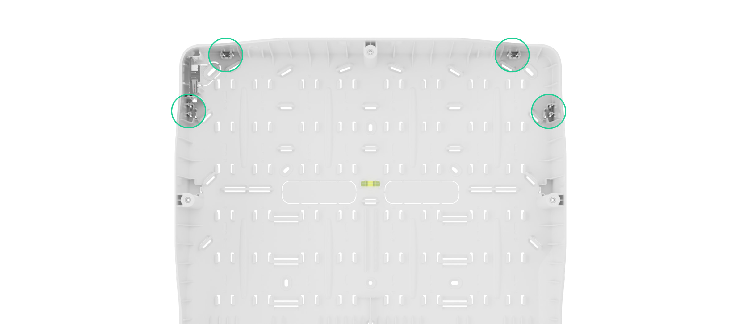
The casing features mounts for the modules, cable channels, and a tamper board that is connected to the hub’s connector. Three Module Holder (type A) holders are required to install the hub board into Ajax Case. The figures below show the options for placing the hub board into the Ajax casings.
How not to install the hub
- Without Case D (430) or Case E (395) (coming soon).
- Outdoors without Case E (395) (coming soon). This may cause the control panel to malfunction.
- In Case E (395) (coming soon) in black in direct sunlight. This may cause the devices inside the casing to overheat and damage their electrical components. Choose shaded places for installation.
- Near metal objects and mirrors. They can cause attenuation or shielding of the radio signal. This may result in a connection loss between the hub and wireless Ajax devices. If it is necessary to install the hub in such conditions, use ExternalAntenna to overcome signal interference.
- In places with high levels of radio interference. This may result in a connection loss between the hub and wireless Ajax devices or false notifications of system jamming. If necessary, use ExternalAntenna to move the reception spot.
- With another hub board in Ajax Case.
-
Closer than 3 ft to a router and power cables. This may result in connection loss between the hub and wireless devices.
-
Closer than 3 ft to Jeweller devices. This may result in connection loss between the hub and these devices.
- In places where the hub will have a signal strength of 1 or 0 bars for connected devices. This may result in connection loss between the hub and these devices. Use ExternalAntenna if necessary.
- In places with temperature and humidity beyond the permissible limits. This may damage the control panel.
- In places with no cellular signal or one-bar signal strength. In areas with poor signal reception, it is recommended to install Ajax ExternalAntenna. If a cellular signal strength is low, correct device operation cannot be guaranteed.
Designing
To ensure correct device installation and configuration, it is crucial to design the system properly. During the design stage, it is necessary to consider factors such as the number and types of devices at the facility, their exact location and installation height, the length and type of Fibra lines, and other relevant details. For tips on designing the Fibra system, refer to the article.
Topologies
Fibra is a data transfer protocol for wired Ajax devices. At the physical level, Fibra resembles a bus connection: the detectors are connected to the control panel with a four-core cable. Ajax systems support three topologies — Beam (Radial wiring), Ring, and Tree. Learn more about the topologies in this article.
Cable length and type
If the Beam (Radial wiring) topology is used, the maximum range of a wired connection is 6,550 ft, while the Ring topology allows for up to 1,640 ft.
Recommended cable types:
- U/UTP cat.5, 4×2×0.51 mm (24 AWG) cable, copper conductor.
- 4×0.22 mm² signal cable, copper conductor.
The wired connection range may vary if you use a different cable type. No other cable types have been tested.
Verification with the calculator (coming soon)
Use Fibra power supply calculator to ensure that the design is correct and the system will work in practice. This tool helps check the communication quality and cable length for wired Fibra devices during the system design stage.
Preparing for installation
Cable arrangement
When preparing to lay cables, check the electrical and fire safety regulations in your region. Strictly follow these standards and regulations. Tips for laying cables are available in the article.
Cable routing
We recommend that you carefully read the Selecting the installation site section before installation. Do not deviate from the system design. Violation of the basic Superior MegaHub (without casing) installation rules and the recommendations of this manual may result in incorrect operation and connection loss with the device.
Signal cables for Fibra devices must be laid at a distance of at least 20 inches from the power cables when routed in parallel. If signal cables intersect, the angle must be 90°. Observe the permissible cable bending radius, which is specified by the manufacturer in the cable specifications. Otherwise, there is a risk of damaging or breaking the conductor. Tips for cable routing are available in this article.
Preparing cables for connection
Remove the insulation layer and strip the cable with a special insulation stripper. The wire ends inserted into the device terminals must be tinned or crimped with a sleeve. This ensures a reliable connection and protects the conductor from oxidation. Tips for preparing the cables are available in the article.
Installation
Before installing Superior MegaHub (without casing), ensure that the optimal device location has been chosen and that it meets the requirements of this manual. To reduce the likelihood of sabotage, conceal the cables from view and route them in a place that is inaccessible to intruders. It is best to route them inside walls, floors, or ceilings. Before final installation, run the Fibra signal strength test.
When connecting to the device terminals, do not twist the wires together, but solder them. The ends of the wires that will be inserted into the terminals must be tinned or crimped with a special sleeve. This will ensure a reliable connection. Follow the safety procedures and electrical installation rules when connecting the control panel and wired devices.
- De-energize the cables you will connect to Superior MegaHub (without casing).
- Unscrew the casing’s front lid and remove it.
- Prepare holes for routing the cables into Case D (430) in advance. Refer to the Case D (430) user manual.
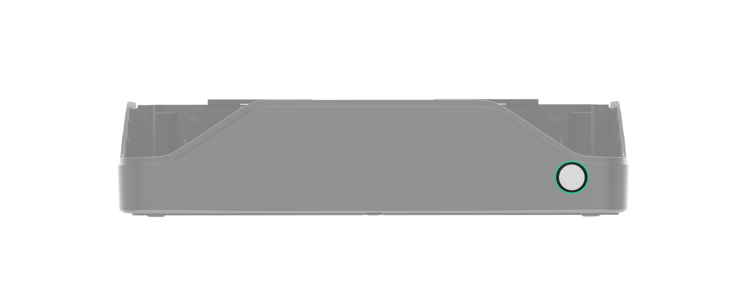
- Drill a Ø10 mm hole for a light guide in the bottom or side of the casing, near the place where the LED board will be installed.
- Install the light guide and the LED board included in the Superior MegaHub (without casing) complete set.
- Run the power and Ethernet cables into Case D (430) through the prepared holes. Run the ExternalAntenna cables if the antennas are used.
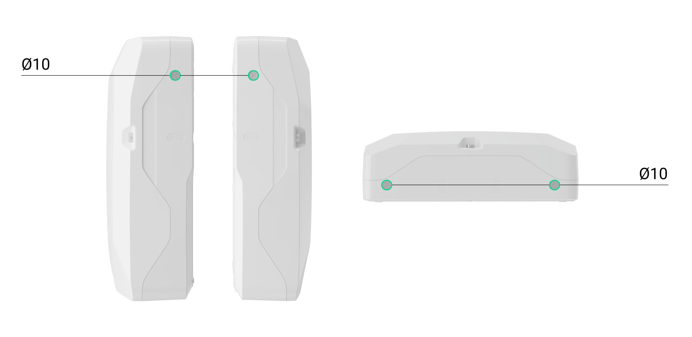
- Using all fixing points, secure Case D (430) to a vertical surface at the selected installation site with the bundled screws. One fixing point is located in the perforated part above the tamper button: if someone attempts to detach the casing, the tamper button will be triggered.
- Secure three Module Holder (type A) holders using the Case rails.
- Install the Superior MegaHub (without casing) board on the holders.
- Install and connect the Case D (430) tamper board to the appropriate hub terminal.
- Connect the LED board to the appropriate hub terminal.
- If necessary, connect Ajax ExternalAntenna antennas to the appropriate hub connectors.

Use only Ajax ExternalAntenna. If a third-party external antenna is used, correct device operation cannot be guaranteed. Before installation, read the ExternalAntenna user manual.
- Install the battery in the designated holders provided in Case D (430). Secure the battery with the hook-and-loop fastener.

Refer to the battery documentation — some batteries can be mounted only vertically (with terminals facing upward). Any other installation position may result in rapid battery degradation.
- Connect the backup battery to the appropriate hub connector using the bundled cable. Observe the correct polarity and wire connection order.
Note: Superior MegaHub (without casing) cannot be connected to third-party power supply units.
Use 12 V⎓ batteries with a capacity of 18 Ah. You can also use a similar battery of a different capacity if it fits in size and its charging time does not exceed 24 hours.
- Connect the Ethernet cable to the appropriate hub connector.
- Connect the power cable to the appropriate hub terminals.
- Secure the cables with cable ties.
- Insert SIM cards into the corresponding slots.
- Add the hub to the system.
- Attach the lid to the casing and secure it with the bundled screws.
- Check the state of the hub casing in the Ajax PRO app. If a tamper alarm is indicated, ensure that Case D (430) is closed tightly.
If the Ethernet connection fails
If the Ethernet connection is not established, disable proxy and MAC address filtering and activate DHCP in the router settings. The hub will automatically receive an IP address. After that, you can assign a static IP address to the hub in an Ajax app.
If the SIM connection fails
To connect to the cellular network, you need to install a micro SIM card with a PIN code request disabled and sufficient funds on your account to pay for services according to the tariff plan. To disable the PIN code request, insert the SIM card into your phone.
If the hub fails to connect to the cellular network, use Ethernet to configure the network parameters, such as roaming, APN access point, username, and password. To obtain these parameters, contact the support service of your mobile operator.
Adding to the system
Use the latest versions of Ajax apps to access all available features and ensure proper system operation.
Superior MegaHub (without casing) can only be added and configured in Ajax PRO apps. Only accredited Ajax Systems partners can sell, install, and maintain Superior products.
You can add the hub to an existing space or create a new one. If you need to transfer the system from one hub to another, refer to this article.
Before adding the hub
- Install the Ajax PRO app.
- Log in to your PRO account or create a new one.
- Ensure an external power supply, backup battery, Ethernet cable, and/or SIM cards are connected to the hub.
- Ensure the hub is turned on. If not, turn on the hub by holding the power button for 3 seconds. Once the hub is turned on, the LED indicator on the hub board will light up.
Adding the hub with space creation
- Open the Ajax PRO app.
- Go to the menu with all spaces and tap
 in the upper right corner to create a space.
 - Assign a name to the space and add an image if necessary.
- Scan the QR code or enter the hub ID manually. You can find the QR code with the ID on the hub board. Also, it is duplicated on the hub packaging.
- Tap Add to create the space with the hub.
Adding the hub to an existing space
- Open the Ajax PRO app. Select a space to which you want to add the hub.
- Go to the Devices
 tab and tap Add device.
 - Scan the QR code or enter the hub ID manually. You can find the QR code with the ID on the hub board. Also, it is duplicated on the hub packaging.
- Assign a name to the hub.
- Select a virtual room or create one if no rooms have been created yet.
- Tap Add, and the countdown will begin.
Once the hub is added to your account, you become the hub admin. Admins can invite other users to the system and determine their rights. You can add up to 1,000 users to Superior MegaHub (without casing).
Each PRO account added to the hub, as well as the monitoring company profile, is considered a system user.
Changing or removing the admin from the list of hub users does not reset the system settings or connected devices.
If there are already users on the hub, the hub admin, PRO with the rights to configure the system, or the installation company maintaining the selected hub can add your account. You will be notified that the hub has already been added to another account. Contact our technical support to determine who has admin rights on the hub.
Adding devices to the hub
Create the necessary virtual rooms before adding devices to the system. The rooms are needed to group devices and increase the information content of notifications. Device and room names are displayed in the text of Ajax system events and alarms.
For more information on how to add and configure a device, refer to its user manual, which can be found on the Ajax Support page.
Adding Jeweller devices
To add a wireless device to the hub, in the Ajax PRO app:
- Go to the Devices tab and tap Add device.
- Scan the QR code or enter the device ID manually. You can find the QR code with the ID on the device enclosure. Also, it is duplicated on the device packaging.
- Assign a name to the device.
- Select a virtual room and a security group (if the group mode is enabled).
- Tap Add, and the countdown will begin.
- Follow the instructions in the app to add the device.
- Repeat steps 1–6 if you need to add more devices.
The device can be added to the hub if it is located within the hub’s radio communication range, on the same secure premises.
Once added to the hub, the device will appear in the list of hub devices in an Ajax app. The interval for updating device states in the list depends on the Jeweller/Fibra settings and is 36 seconds by default.
Connecting Fibra devices
Fibra wired communication technology allows creating segments up to 6,550 ft long. Superior MegaHub (without casing) features eight lines compatible with all Fibra devices, regardless of their type. Security detectors, keypads, and sirens are connected to the same line and protect a specific facility area. Up to 200 devices can be connected to one beam or ring of the Fibra lines.
Before installing the devices, ensure that you have chosen the optimal location and that it meets the conditions specified in the device user manual. To reduce the likelihood of sabotage, hide the cables from view and route them in a place that is inaccessible to intruders. It is best to route them inside walls, floors, or ceilings. Before final installation, run the Fibra signal strength test.
To connect a wired device to the hub:
- De-energize and turn off the hub. Disconnect the backup battery.
- Run four-wire cables into the casing. Connect the cables to Superior MegaHub (without casing) line terminals:
- Connect the other end of the four-wire cable to the terminals of the first device in the line, observing the polarity and wire connection order. Securely fasten the cable to the device terminals.
- If other devices are connected to the segment, prepare and connect the cables for the next device to the terminals.
- Connect other devices to the line if necessary.
- Install a 120 Ω terminating resistor for the last device in the line using the Beam (Radial wiring) topology. The terminating resistor is installed between terminals A and B of the last device in the line.
With the Ring topology, a terminating resistor is not needed. In this case, connect the last device in the line to the next hub’s Fibra line.
The nominal value of terminating resistors is 120 Ω. Terminating resistors are included in the complete set of Superior MegaHub (without casing).
- Connect the power supply to the hub and turn it on.
- Add devices to the system manually or via line scanning.
- Run the Fibra signal strength test for each connected device. The recommended signal strength is two or three bars. Otherwise, check the cable connection and integrity or move the system devices.
Adding Fibra devices
In the Ajax PRO app, there are two ways to add devices: manually and automatically. You can add a few devices manually, for example, when replacing a faulty detector with a new one. Automatic line scanning is useful when you add numerous devices.
- Go to the Devices tab and tap Add device.
- Scan the QR code or enter the device ID manually. You can find the QR code with the ID on the device enclosure. Also, it is duplicated on the device packaging.
- Assign a name to the device.
- Select a virtual room and a security group (if the group mode is enabled).
- Tap Add.
The device connected to the hub will appear in the list of hub devices in an Ajax app.
The device state update interval depends on the Fibra settings and is 36 seconds by default.
To help an installer name the device correctly or assign it to a room and group, we have provided two methods to identify the device: by LED indication and by triggering a device.
Select any device from this list. The device’s LED indicator will start flashing. After the device has been identified, add it to the hub.
To add a device to the hub:
- Select the device from the list.
- Assign a name to the device.
- Specify a room and group if the group mode is enabled.
- Tap Save.
- The added device will be removed from the list of devices available to add.
If the maximum number of devices has already been added to the hub, an error notification will appear when you attempt to add another device. A total of 999 devices can be added to Superior MegaHub (without casing), including 200 wired devices on one Fibra line beam or ring.
Connected Ajax devices work with only one hub. Once added to a new hub, these devices are not removed from the device list of the old hub. This must be done via the Ajax PRO app.
Icons
Icons display some of the Superior MegaHub (without casing) states. The icons are displayed in the Devices ![]() tab in an Ajax app.
tab in an Ajax app.
| Icon | Meaning |
|
The extra services are activated according to the subscription plan. |
|
| The hub operates in the 2G network. | |
| The hub operates in the 4G (LTE) network. | |
| No SIM cards. Insert at least one SIM card. | |
| A SIM card is faulty or has PIN verification enabled. Check the SIM card in your phone and disable the PIN code request. | |
| Hub battery charge level. Specified as a percentage in 1% increments. | |
| The backup battery is not connected. | |
|
The hub is directly connected to the monitoring station. The icon is not displayed if a direct connection is neither available nor configured. |
|
|
The hub is not directly connected to the monitoring station. The icon is not displayed if a direct connection is neither available nor configured. |
|
| The hub operates in Saving mode. | |
| The hub has lost connection with the Ajax Cloud server. |
States
The states include information about the hub and its operating parameters. The Superior MegaHub (without casing) states can be viewed in Ajax apps:
- Go to the Devices tab.
- Select Superior MegaHub (without casing) from the list.
| Parameter | Meaning |
| Malfunction |
Tap The field is displayed only if a malfunction is detected. |
| Cellular signal strength |
Signal strength of the active SIM mobile network. Install the hub in places where a cellular signal strength is 2–3 bars. In places with poor signal reception, it is recommended to install Ajax ExternalAntenna. If the hub is installed in a place with a weak or unstable signal strength, the hub will not be able to call or send an SMS about an event or alarm. |
| External antenna for cellular | External antenna connection state:
External antenna damage can be detected only when Ajax ExternalAntenna is connected and the hub casing is closed properly. |
| Wi-Fi signal strength | Wi-Fi signal strength via the Wi-Fi communication channel. The recommended value is 2–3 bars. |
| External antenna for Jeweller | External antenna connection state:
External antenna damage can be detected only when Ajax ExternalAntenna is connected and the hub casing is closed properly. |
| External antenna for Wings | External antenna connection state:
External antenna damage can be detected only when Ajax ExternalAntenna is connected and the hub casing is closed properly. |
| Connection | Connection state between the hub and Ajax Cloud:
If Superior MegaHub (without casing) is not connected to the Ajax Cloud server, the hub and all connected device icons become semi-transparent in the device list. |
| Battery charge |
The charge level of the connected battery. Specified as a percentage in 1% increments. If charge level is 20% or below, the hub will notify users of a low battery charge. |
| Lid | State of the tamper button that is triggered when Ajax Case is dismantled or opened:
|
| Lines power supply | Power supply state of the hub’s Fibra lines:
|
| Line [number] / Ring [number] | State of a single line or ring in case of a malfunction:
Information about each line or ring is displayed in a separate row. |
| External power | External power supply connection state:
|
| Cellular data | State of the hub’s mobile internet connection:
If a cellular signal strength is 1–3 bars and the hub has enough funds and/or bonus SMS/calls, it will be able to call and send SMS messages even if the Not connected state is displayed. |
| Wi-Fi | State of the hub’s internet connection via Wi-Fi:
|
| Ethernet | State of the hub’s internet connection via Ethernet:
|
| SIM 1 |
Number of the SIM card installed in the first slot. To copy the number, tap it. If the phone number is displayed as Unknown number, the mobile operator has not saved it to the SIM card memory. |
| SIM 2 |
Number of the SIM card installed in the second slot. To copy the number, tap it. If the phone number is displayed as Unknown number, the mobile operator has not saved it to the SIM card memory. |
| Average noise (dBm) |
Average noise level in the radio channel. Measured at the hub installation site. The first two values show the noise level at Jeweller frequencies, while the third indicates the level at Wings frequencies. An acceptable value is –80 dBm or lower. For example, –95 dBm is considered acceptable, while –70 dBm is invalid. |
| Frequency hopping | State of the frequency hopping feature. |
| Monitoring station | State of the hub’s direct connection to the monitoring station:
If this field is displayed, the monitoring company uses a direct connection to receive system alarms and events. |
| Telephony |
State of the telephony feature. |
| Scheduled wake-up |
State of the scheduled wake-up feature. The feature allows setting the date and time when the hub wakes up from the battery saving mode on demand and becomes active for configuration and management. The available states are:
Tap |
| Hub model |
Hub model name. |
| Hardware | Superior MegaHub (without casing) hardware version. Not updatable. |
| Firmware |
Superior MegaHub (without casing) firmware version. Remotely updatable. |
| Device ID |
Superior MegaHub (without casing) identifier (first eight digits of the serial number). The identifier is shown on the device packaging and on the board under the QR code. |
| IMEI | A unique 15-digit serial number for identifying the hub’s modem in the GSM network. It is displayed only when a SIM card is installed in the hub. |
Settings
To change Superior MegaHub (without casing) settings, in an Ajax app:
- Go to the Devices tab.
- Select Superior MegaHub (without casing) from the list.
- Go to Settings
 .
. - Set the required parameters.
- Tap Back to save the new settings.
Name
The hub name is displayed in the SMS and push notification text. The name can contain up to 24 Latin characters or up 12 Cyrillic characters.
To change the name, tap on the pencil icon ![]() and enter the new hub name.
and enter the new hub name.
Room
Selecting a virtual room to which the hub is assigned. The room name is displayed in the SMS and push notification text.
Select casing
Selecting the type of casing into which the Superior MegaHub (without casing) board is installed. The casing image is displayed in the device-related settings and notifications.
Ethernet
Settings for a wired internet connection.
- Connection via Ethernet — allows turning on/off the hub’s Ethernet module.
- Connection type — allows selecting the method for the hub to obtain an IP address. If DHCP is selected, the hub automatically obtains its IP address and other network settings. The Static option allows you to manually set the IP address and other network settings for the hub.
- IP address — the hub IP address.
- Subnet mask — the subnet mask in which the hub operates.
- Gateway — the gateway used by the hub.
- DNS — the hub DNS.
Cellular
Settings for the mobile network and installed SIM cards. In the main menu, you can change the settings for both SIM cards. In the submenu, it is possible to configure settings for each SIM card separately.
Modem settings
- Cellular data — allows turning on/off the hub’s cellular module.
- Roaming — if this setting is enabled, SIM cards can operate in roaming mode.
- Ignore network registration error — if this setting is enabled, the hub ignores errors when connecting to the network via a SIM card. Enable this setting if the SIM card cannot connect to the network.
- Disable communication check with the operator — if this setting is enabled, the hub ignores errors when connecting to the mobile operator. Enable this setting if the SIM card cannot connect to the network.
SIM cards
- SIM 1 — displays the number of the installed SIM card. If the phone number is displayed as Unknown number, it means the mobile operator has not saved it to the SIM card memory. Tap the field to open the SIM card settings.
- SIM 2 — displays the number of the installed SIM card. If the phone number is displayed as Unknown number, it means the mobile operator has not saved it to the SIM card memory. Tap the field to open the SIM card settings.
SIM card settings
APN, Username, and Password — settings for connecting the hub to the internet via a SIM card. To obtain the settings of your mobile operator, contact your provider’s support service. APN settings are applied only after a successful internet connection with new parameters is established. If the connection attempt fails, the hub continues to work with the previous APN settings.
Mobile data usage. The menu contains information about mobile traffic used by an Ajax system, allowing you to reset the statistics and check the SIM card balance.
The data is calculated by the hub and may differ from the operator’s statistics. This is because each mobile operator calculates incoming and outgoing traffic individually.
- Incoming — the amount of data received by the hub. Displayed in KB or MB.
- Outgoing — the amount of data sent by the hub. Displayed in KB or MB.
Reset statistics — allows resetting the statistics for incoming and outgoing traffic.
Check balance
USSD code. Enter the code used to check the balance in this field. For example, *111#. To send a request, tap Check balance after entering the code. The request result will be displayed under the balance check button.
Communication method
The setting allows selecting the preferred antenna for cellular data transmission:
- Auto-switching between antennas — the hub will prioritize Ajax ExternalAntenna if it is available (connected and not damaged).
- External — the hub does not switch to an internal antenna and tries to use only the external one.
- Built-in — the hub uses an internal antenna.
Wi-Fi
Settings for Wi-Fi internet connection. The general list displays all networks available to the hub.
- Wi-Fi — allows turning on/off Wi-Fi on the hub. Once the network is selected, its settings open.
- DHCP/Static — allows selecting the method for the hub to obtain an IP address. If DHCP is selected, the hub automatically obtains its IP address and other network settings. The Static option allows you to manually set the IP address and other network settings for the hub.
- IP address — the hub IP address.
- Subnet mask — the subnet mask in which the hub operates.
- Gateway — the gateway used by the hub.
- DNS — the hub DNS.
- Forget this network — if this option is selected, the hub will delete the network settings and disconnects from it.
Keypad access codes
The setting allows configuring keypad codes for people who are not registered in the system.
You can create a code for people who are not added to the space. This is convenient, for example, to provide a cleaning company with access to security management. An unregistered user simply needs to enter the access code on the Ajax keypad to arm or disarm the system.
To set the access code for an unregistered user in the system:
- Tap Add code.
- Set Username and Access сode.
- Tap Add.
To set a duress code, change the access code, configure group access, Night mode, or code ID, or temporarily disable or delete this code, select it from the list and make the necessary changes.
The created access codes are valid for all keypads connected to the hub. Superior MegaHub (without casing) supports up to 1,000 access codes.
The access code must contain 4 to 6 digits.
Superior MegaHub (without casing) supports over 1,000,000 code variations.
Code length restrictions
This setting is only available in Ajax PRO apps.
Set the requirements for the length of codes used for user authorization and system access. You can choose the Flexible (4 to 6 symbols) option or set a fixed code length: 4 symbols, 5 symbols, or 6 symbols.
Note: when you set the fixed code length, the system resets all previously configured access codes.
The fixed code length is required for the Easy armed mode change feature. It allows users to disarm the system without pressing the ![]() Disarm button on the keypad once the code is entered or an access device is used.
Disarm button on the keypad once the code is entered or an access device is used.
Detection zone test
This setting allows running the Detection zone test for connected devices. With this test, you can check the operation of devices and their alarm detection zone.
Walk test
With this test, you can check all detectors and ensure their proper operation. When the system is switched to the testing mode, it does not raise an alarm or send it to monitoring software. This allows each detector or device to be triggered without causing a false alarm. However, the system still reports malfunctions and tamper alarm events to monitoring software.
In the Walk test menu, you can set the Walk test auto-exit time, review the latest test results, and start/stop the test.
Jeweller/Fibra
Setting the polling period between the hub and connected devices. The setting indicates how often the hub communicates with the devices and how quickly a connection loss is detected.
- Device ping interval, sec — the frequency of polling connected devices by the hub; set in the range from 12 to 300 seconds. The default value is 36 seconds. The value is configured for both wired and wireless devices.
- Number of missed pings to determine connection failure — a counter of undelivered packets. The value is configured separately for wireless and wired devices and is eight packets by default.
Do not reduce the default polling interval value unnecessarily.
The time after which the system sends a message about a connection loss between the hub and the device is calculated with the following formula:
Device polling interval × Number of missed polls to determine connection failure
The shorter the polling period, the faster the hub will know about the connected device events, and the faster the devices will receive hub commands. Information about alarms and sabotage attempts is transmitted instantly, regardless of the polling interval. Reducing the polling period will affect the battery life of wireless devices.
The polling interval limits the maximum number of connected devices:
| Interval, s | Device limit | Interval, s | Device limit |
| 12 | 39 | 168 | 559 |
| 24 | 79 | 180 | 599 |
| 36 (by default) | 119 | 192 | 639 |
| 48 | 159 | 204 | 679 |
| 60 | 199 | 216 | 719 |
| 72 | 239 | 228 | 759 |
| 84 | 279 | 240 | 799 |
| 96 | 319 | 252 | 839 |
| 108 | 359 | 264 | 879 |
| 120 | 399 | 276 | 919 |
| 132 | 439 | 288 | 959 |
| 144 | 479 | 300 | 999 |
| 156 | 519 |
The hub supports both devices with the new firmware version (i.e., with the “999 ready” label) and devices with the legacy firmware version. However, no more than 250 devices with the legacy firmware can be added to the hub. The remaining devices within the 999 limit must have the new firmware version.
Send alarm when connected device goes offline — when enabled, events about connection loss are sent as alarms to all system users.
Radio interference detection — the following settings ensure the system complies with the EN 50131 (Grade 3) requirements. There are two options:
- Advanced radio interference detection.
- Send radio interference detection event as alarm — if enabled, the notification of a high radio interference level will be sent as an alarm to all system users.
Communication method
The setting allows selecting the preferred antenna for communication with devices via Jeweller and Wings channels:
- Auto-switching between antennas — the hub will prioritize Ajax ExternalAntenna if it is available (connected and not damaged).
- External — the hub does not switch to an internal antenna and tries to use only the external one.
- Built-in — the hub uses an internal antenna.
Lines
A group of settings for wired Fibra devices.
Line power supply — allows controlling the power supply of the Superior MegaHub (without casing) lines. Opens a menu where you can enable or disable each line power supply. When the setting is enabled, power is supplied to Fibra devices connected to the selected line. Power is on by default.
Ring-connected lines — allows creating a ring in the app and then manually connecting lines by selecting the relevant inputs.
Line power test — allows running the Superior MegaHub (without casing) line power test. It simulates the maximum possible power consumption: detectors raise alarms, keypads are activated, and sirens are turned on.
If the test is successful, all wired devices will have enough power in any situation.
When the line power test is running, the wired sirens connected to the hub are activated.
Add all Fibra devices — allows running Fibra line scanning. The feature shows all wired devices connected to the hub. This helps quickly configure device names, groups, and rooms.
Telephony settings
This setting is only available in Ajax PRO apps.
Telephony settings allow configuring the hub to communicate with the monitoring station via the SIP protocol.
In Ajax PRO Desktop, you can create and apply a telephony setting template to save time when configuring multiple systems.
Service
Hub service settings are divided into two groups: general settings and advanced settings.
General settings
LED brightness
This setting allows configuring the hub’s LED indicator brightness.
Firmware update
The menu contains the hub firmware update settings.
- Firmware auto-update configures automatic OS Malevich updates. The setting is enabled by default:
- If enabled, the firmware is automatically updated when a new version is available. The system must be disarmed, and an external power source must be connected to the hub.
- If disabled, the system is not updated automatically. If a new firmware version is available, the app will prompt you to update OS Malevich.
- Check for new version allows manually checking and installing firmware updates when they are available or assigned to the hub. This option is available only when the Firmware auto-update setting is enabled.
If the hub firmware is outdated, an error may occur when you add a device to the hub. In this case, the system will prompt you to open the Firmware update section in the Service settings and check for a new firmware version. If it is available, you can proceed with an on-demand firmware update.
Hub system logging
This setting allows selecting the hub log transmission channel or disabling log recording:
- Ethernet — system logs are transmitted via the Ethernet channel.
- Wi-Fi — system logs are transmitted via the Wi-Fi channel.
- Off — logging is disabled.
Logs are files containing information about system operation. Do not disable the logs, as this information may be helpful in case of system errors.
Delaying notifications of external power loss
This setting allows configuring a delay time for sending an external power loss notification.
You can select the delay time from 1 minute to 1 hour in 1-minute increments.
“While hub offline” event amount
In case of server connection failure, events are recorded in the hub buffer and will be delivered to Ajax apps once the connection is restored.
This setting allows choosing the number of recent events that the hub will send to Ajax apps after returning to normal operation.
You can select from 100 (default value) to 1,000 events with an increment of 50 events.
Advanced settings
PD 6662 setting wizard
The setting allows opening a step-by-step guide for configuring the system in accordance with the PD 6662:2017 British security standard.
Server connection
These settings allow configuring the connection between the hub and the Ajax Cloud server:
- Delay of server connection failure alarm. The delay is necessary to reduce the risk of false notifications of a connection loss with the Ajax Cloud server. It is activated after three unsuccessful hub–server polls. The delay can be set in the range from 30 to 600 s. The recommended default value is 300 s.
- Hub-server polling interval, sec. Indicates the frequency of polling requests from the hub to the Ajax Cloud server. It can be set in the range from 10 to 300 s. The recommended default value is 60 s.
The time before the hub sends a notification of a connection loss with the Ajax Cloud server is calculated with the following formula:
(Polling interval × 3) + Time filter.
With the default settings, Ajax Cloud detects a connection loss with the hub within 8 minutes:
(60 s * 3) + 300 s = 8 min.
- Get notified of server connection loss without alarm. Ajax apps can notify users of a connection loss between the hub and the server in two ways: with a standard push notification or with a siren sound (enabled by default). When the option is active, the notification comes as a standard push.
- Notify of connection loss over channels. An Ajax system can notify both users and the monitoring company of a connection loss between the hub and the Ajax Cloud server even via one of the communication channels.
In the menu, you can select the communication channels through which the system will notify users of a connection loss, as well as the transmission delay for such notifications.
- Loss notification delay — the delay time before the system sends a connection loss notification via one of the communication channels. The delay can be set in the range from 3 to 30 minutes.
The time for the system to send a connection loss notification via one of the communication channels is calculated with the following formula:
(Polling interval × 3) + Time filter + Notification delay.
Sounds and alerts
These settings are divided into three groups.
Alert with siren
If lid of hub or any detector is open. When the setting is enabled, the hub activates the connected sirens if the enclosure of the hub, detector, or any other Ajax device is open.
If in-app panic button is pressed. When the setting is enabled, the hub activates the connected sirens if the panic button is pressed in an Ajax app.
You can disable the siren response to pressing the panic button of Ajax key fob in its settings in an Ajax app (Devices ![]() → Ajax key fob → Settings
→ Ajax key fob → Settings ![]() ).
).
Restart alarm signal on triggering of each detector. If the setting is enabled, each new alarm from the intrusion detector will restart the siren alarm. You can disable this setting so that the siren only responds to alarms from the first detector that was triggered.
Beep with keypad
This setting is only available in Ajax PRO apps.
The keypads added to the hub will emit an audible signal to inform users of malfunctions. To activate audible notifications, enable the If any device is offline and If battery of any device is low toggles.
Ajax keypads with the following or later firmware versions support audible malfunction notifications:
- 5.57.1.1 for KeyPad Jeweller;
- 5.57.5.0 for KeyPad Plus Jeweller;
- 6.57.11.12 for Superior KeyPad Fibra.
Battery settings
These settings are divided into the following groups:
- Battery power saver
- Maximize battery life
- Stop battery charging if faulty
- Notify if battery fails to charge
This setting is only available in Ajax PRO apps.
Battery power saver
The Save hub backup battery charge setting allows for extending the backup battery life when an external power supply is unavailable. When this setting is enabled, the hub switches to standby mode once it loses the external power supply.
To save the backup battery charge, the hub disables its connection channels (cellular network, Ethernet, and Wi-Fi) when it switches to standby mode. Therefore, the hub in standby mode is not connected to Ajax Cloud and the monitoring station until any system event occurs. In Ajax apps, the hub and devices added to it will be greyed out and unavailable for configuration or control; the hub will be in the Saving mode state, and the devices added to it will be Offline. The space in the space list will be marked with the additional Saving mode state.
Standby mode does not affect system operation. Any detector triggering activates the hub for a specified time to transmit the event to users and the monitoring station. In standby mode, the hub LED flashes red every 30 seconds, and the LED brightness is reduced to the minimum.
If the hub is in standby mode, switching security modes is possible only via an Ajax keypad or a key fob. Switching system security modes and configuring the hub in standby mode via Ajax apps are not provided.
Enable Save hub backup battery charge to configure the hub operation time:
| Setting | Meaning |
| Activity period | The time during which the hub remains connected to Ajax Cloud after any system event occurs is set to 10 minutes by default. However, you can configure this time from 5 minutes to 1 hour. |
| Server polling interval | The time between the hub connections to the server in standby mode is set to 6 hours by default. However, you can adjust this time from 1 hour to 24 hours. |
The Battery power saver feature allows extending the backup battery life up to 200 hours for Superior MegaHub (without casing) when a 12 V⎓ backup battery with a capacity of 18 Ah is used. This time depends on the system configuration and the number of devices added to the hub.
When the Battery power saver feature is enabled, your system does not comply with EN 50131 (Grade 2, 3).
Note: if there is at least one range extender added to the hub via Ethernet in your system, the hub will not switch to standby mode. This is necessary to maintain the connection with devices added via the range extender.
For systems with voice modules: the monitoring station operator can communicate via voice modules only during the hub’s Activity period when the hub stays connected to Ajax Cloud. An ongoing call can not prolong the hub’s activity period; therefore, the call will end automatically once the hub switches to Saving mode.
Maximize battery life
The Maximize battery life feature extends the life of the hub’s backup battery. When the setting is enabled, charging stops at 100% and resumes at 80% battery charge.
Stop battery charging if faulty
When this setting is enabled, the battery stops charging automatically if a malfunction occurs after 40 hours of continuous charging. Reconnect the battery to resume charging.
Notify if battery fails to charge
When this setting is enabled, you will receive a notification if the battery has not reached a full charge for a long period. This setting is enabled by default.
Fire detectors settings
These settings allow configuring the Interconnected fire detector alarm feature, which activates the built-in sirens of all Ajax fire detectors if at least one of them is triggered.
System integrity check
This setting allows checking the state of security detectors, devices, and followed groups before the system is armed. System integrity check is disabled by default.
Alarm confirmation
This setting is only available in Ajax PRO apps.
This is a special event that the hub sends to the monitoring station and system users if several devices specified by an admin have been triggered within a specified period of time.
By responding to confirmed alarms, the monitoring company and the police reduce the number of unnecessary dispatches.
Restoration after alarm
This setting is only available in Ajax PRO apps.
The feature prevents the system from being armed if an alarm has been previously registered. To arm the system, an authorized user or PRO must restore it. The types of alarms that require system restoration are defined during feature configuration.
The feature eliminates situations when a user arms the system with detectors that generate false alarms.
Arming/disarming process
This setting is only available in Ajax PRO apps.
The first Compliance with standard option allows selecting a specific standard for configuring the system according to existing requirements. Once you select the required standard, the menu will show the appropriate arming/disarming settings below. The following standards are available:
- EN 50131 — European standard for intrusion and hold-up alarm systems, which also describes the security grades concept.
- PD 6662 — British standard for intrusion and hold-up alarm systems, aimed to reduce the number of unconfirmed alarms and ensure police response only to real threats.
- VdS — German standard for intrusion and hold-up alarm systems, which regulates arming/disarming process.
- ANSI/SIA CP-01-2019 — American standard for security systems that regulates features and requirements for reducing false alarms caused by users or equipment.
EN 50131
Once EN 50131 is enabled, you can configure the Two-stage arming, Exit time restart, and Exit error parameters in the arming settings, as well as set the Alarm transmission delay in the disarming settings.
PD 6662
Once PD 6662 is selected, the menu displays the number of arming/disarming settings that allow configuring the system in accordance with standard requirements.
Use the corresponding step-by-step guide in the Ajax PRO app for a quick and convenient system setup in accordance with PD 6662. Go to Hub → Settings ![]() → Service → PD 6662 setting wizard and follow the app prompts.
→ Service → PD 6662 setting wizard and follow the app prompts.
VdS
Once VdS is enabled, all devices in the system will operate without exit delays; however, entry delays will still be in effect.
The system automatically checks whether all doors and locks are closed. The door is locked with the third-party Blocking element when the system is armed. Additionally, the system checks whether the door is locked to ensure that the system is armed according to the unavoidability principle (German: Zwangsläufigkeit).
The system cannot be armed if it has malfunctions. If there are any malfunctions or the door is not locked, the system sends a notification of the unsuccessful arming event.
ANSI/SIA CP-01-2019
Only Hub 2 (4G) Jeweller and Hub 2 Plus Jeweller are certified in accordance with ANSI/SIA CP-01-2019.
Once ANSI/SIA CP-01-2019 is enabled, you can configure Exit time restart and Unvacated premises in the arming settings. In the disarming settings, you can select which devices should signal Alarm cancellation or Alarm abort and configure the Alarm abort window timeout.
Also, this standard requires several system features to be enabled, such as entry/exit delays, cross zoning, device auto-deactivation, and system testing. These features are configured in the hub and specific device settings.
Day alarm
This setting is only available in Ajax PRO apps.
Day alarm is a special security mode that allows monitoring certain areas of the facility and controlling access to them when the system is disarmed.
Devices auto deactivation
This setting is only available in Ajax PRO apps.
This feature allows ignoring alarms and/or other device events without removing them from the system. Events from disabled devices will not be sent to system users and the monitoring company.
There are three types of device auto-deactivation: by timer, by number of alarms, and by number of similar events. It is also possible to manually deactivate a specific device.
LED indication
This setting is only available in Ajax PRO apps.
This setting allows selecting the system states and events that the hub’s LED indicator will display. One of two options can be chosen:
- Hub–server connection — the hub’s LED indicator shows whether the hub is connected to the power supply and the internet.
- British disco — the hub’s LED indicator shows information about system alerts and malfunctions, security mode changes, and entry/exit delays.
For more information, refer to the Indication section.
After-alarm indication
The siren or keypad can indicate alarms in the armed system using LED indication. This feature allows users and passing security patrols to see that an alarm has been activated in the system.
User manual
If you tap this option, the Superior MegaHub (without casing) user manual will open in an Ajax app.
Transfer settings to another hub
This option allows for automatic transfer of the devices and settings to another hub. Note that you are in the settings of the hub from which you want to export data.
Remove hub
This option allows you to remove the hub and devices added to it from the space. While space remain active, hub and connected devices will be deleted from it. Other users on this space also lose access to these devices.
Space settings
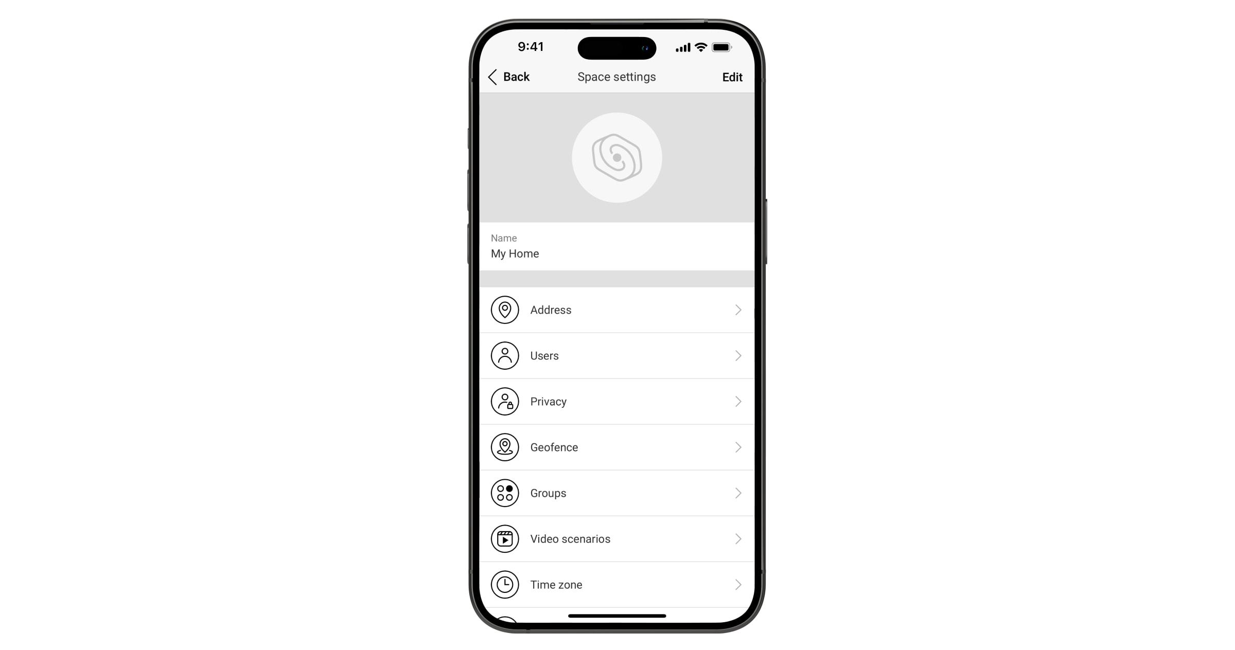
In the space settings, you can configure the following:
- Image and name
- Address
- Users
- Privacy
- Geofence
- Groups
- Video scenarios
- Time zone
- Security companies
- Installers/Companies
You can change space settings in an Ajax app:
- Select a space if you have several or if you are using the Ajax PRO app.
- Go to the Control
 tab.
tab. - Go to Settings by tapping the gear icon at the bottom of the tab.
- Set the required parameters.
- Tap Back to save the new settings.
Indication
Superior MegaHub (without casing) has two LED indication modes:
- Hub – server connection.
- British disco.
Hub – server connection
Hub–server connection mode is enabled by default. The hub’s LED lights up in different colors depending on the system state or event, such as red, white, purple, yellow, blue, or green.
Superior MegaHub (without casing) states can also be monitored in Ajax apps.
| Event | Indication | Note |
| At least two communication channels are connected: Ethernet, Wi-Fi, or cellular. | Lights up white. | When the hub operates on a backup battery only, the LED indicator flashes every 10 seconds. |
|
One communication channel is connected: Ethernet, Wi-Fi, or cellular. |
Lights up green. | When the hub operates on a backup battery only, the LED indicator flashes every 10 seconds. |
| The hub has no connection to the internet or the Ajax Cloud server. | Lights up red. | When the hub operates on a backup battery only, the LED indicator will flash every 10 seconds. |
| External power supply is disconnected (if a backup battery is connected). | Lights up continuously for 3 minutes, then flashes every 10 seconds. | The indication color depends on the number of connected communication channels. |
If the system event indication differs from that specified in this user manual, contact Ajax support.
British disco
You can enable this feature in the hub settings in the Ajax PRO app (Hub → Settings → Services → LED indication).
| Event | Indication | Note |
| Hub state changes | ||
| Two-stage arming or Exit delay. | Flashes white once per second. | One of the devices is performing Two-stage arming or Exit delay. |
| Entry delay. | Flashes green once per second. | One of the devices is performing Entry delay. |
| Arming is complete. | Lights up white for 2 seconds. | The hub (or one of the groups) changes its state from Disarmed to Armed. |
| Disarming is complete. | Lights up green for 2 seconds. | The hub (or one of the groups) changes its state from Armed to Disarmed. |
| Alerts and malfunctions | ||
| Confirmed hold-up alarm. | Flashes red and purple sequentially for 5 seconds. |
There is an unrestored state after a confirmed hold-up alarm. The indication is displayed only if the restoration after Confirmed hold-up alarm is enabled in the settings. |
| Single hold-up alarm. | Lights up red for 5 seconds. |
There is an unrestored state after a hold-up alarm. The indication is not displayed if there is a confirmed hold-up alarm state. The indication is displayed only if the restoration after Single hold-up alarm is enabled in the settings. |
| The number of flashes corresponds to the number of the hold-up device that first activated a hold-up alarm. | Flashes red. | There is an unrestored state after the confirmed or unconfirmed hold-up alarm. |
| Confirmed intrusion alarm. | Flashes yellow and purple sequentially for 5 seconds. |
There is an unrestored state after the confirmed intrusion alarm. The indication is displayed only if the restoration after Confirmed intrusion alarm is enabled in the settings. |
| Single intrusion alarm. | Lights up yellow for 5 seconds. |
There is an unrestored state after the intrusion alarm. The indication is not displayed if there is a confirmed intrusion alarm condition. The indication is displayed only if the restoration after Single intrusion alarm is enabled in the settings. |
| The number of flashes corresponds to the number of the device that first activated an intrusion alarm. | Flashes yellow. | There is an unrestored state after the confirmed or unconfirmed intrusion alarm. |
| Lid opening. | Flashes red and blue sequentially for 5 seconds. |
The hub or any device added to it has the unrestored tamper button state or the open lid. The indication is displayed only if the restoration after Lid opening is enabled in the settings. |
| Other malfunctions. | Flashes yellow and blue sequentially for 5 seconds. |
There is an unrestored fault state, or the hub or any device has a malfunction. The indication is displayed only if the restoration after Other malfunctions is enabled in the settings. |
| Temporary deactivation. | Lights up dark blue for 5 seconds. | One of the devices is temporarily deactivated, or the lid state notifications are disabled. |
| Automatic deactivation. | Lights up blue for 5 seconds. | One of the devices is automatically deactivated by an opening timer or the number of detections. |
|
Alarm timer expiration. |
Flashes green, then blue in sequence. | The indication is displayed after the alarm timer has expired (to confirm an alarm). |
When there are no events in the system, the LED indicator displays two hub states:
- Armed / partially armed, or Night mode enabled — the LED lights up white.
- Disarmed — the LED lights up green.
When the British disco indication is displayed
Superior MegaHub (without casing) users can see the British disco indication after they:
- arm/disarm the system using the Ajax keypad;
- enter the correct user ID or personal code on the keypad and perform an action that has already been performed (for example, the system is disarmed, and the disarm button is pressed on the keypad);
- press the key fob button to arm/disarm the system or activate Night mode;
- arm/disarm the system in Ajax apps.
All users can see the indication related to hub state changes.
Alert indication
If the system is disarmed and any indication from the table is present, the LED indicator flashes yellow once per second.
If there are multiple events in the system, the indications are displayed sequentially, in the same order as shown in the table.
Malfunctions
If a hub malfunction is detected (e.g., no external power supply is available), a malfunction counter is displayed on the device icon in an Ajax app.
All malfunctions can be viewed in the hub states. Fields with malfunctions will be highlighted in red.
Resetting to factory defaults
To reset the hub to factory defaults:
- Turn on the hub if it is off.
- Remove all users and installers from the hub.
- Hold the power button for 30 seconds, and the LED indicator on the hub board will start flashing red.
- Remove the hub from your account.
Maintenance
Regularly check the operation of Superior MegaHub (without casing) and connected devices. The optimal frequency of checks is once every three months. Clean the hub casing of dust, cobwebs, and other contaminants as they appear. Use a soft, dry cloth suitable for equipment care.
Do not use substances containing alcohol, acetone, petrol, or other active solvents to clean the device.
Technical specifications
Warranty
Warranty for the Limited Liability Company “Ajax Systems Manufacturing” products is valid for 2 years after the purchase.
If the device does not operate properly, we recommend contacting Ajax technical support first. In most cases, technical issues can be resolved remotely.
Contact technical support:
Manufactured by “AS Manufacturing” LLC
