Superior MultiRelay Fibra is a module to control electrical appliances’ power supply remotely. The device has four relays with electrically isolated dry contacts. The relays can control the power supply of electrical appliances connected to the circuit. To change the states of the relays, use the Ajax apps, create automation scenarios, or press Button.
The module works as a part of an Ajax system and exchanges data with the hub using the secure Fibra wired communication protocol.
The device is compatible with Superior Hub Hybrid (2G) and Superior Hub Hybrid (4G). Connection to other hubs, radio signal range extenders, ocBridge Plus and uartBridge is not provided.
MultiRelay is a part of the Fibra product line of wired devices. Only accredited Ajax Systems partners can buy, install, and administer Fibra products.
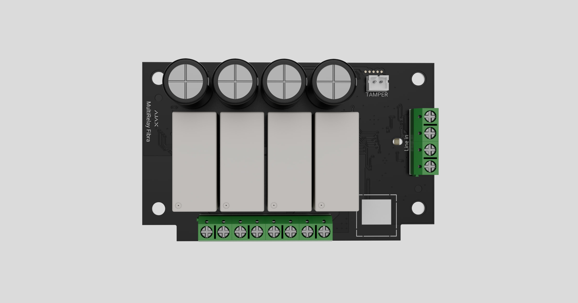
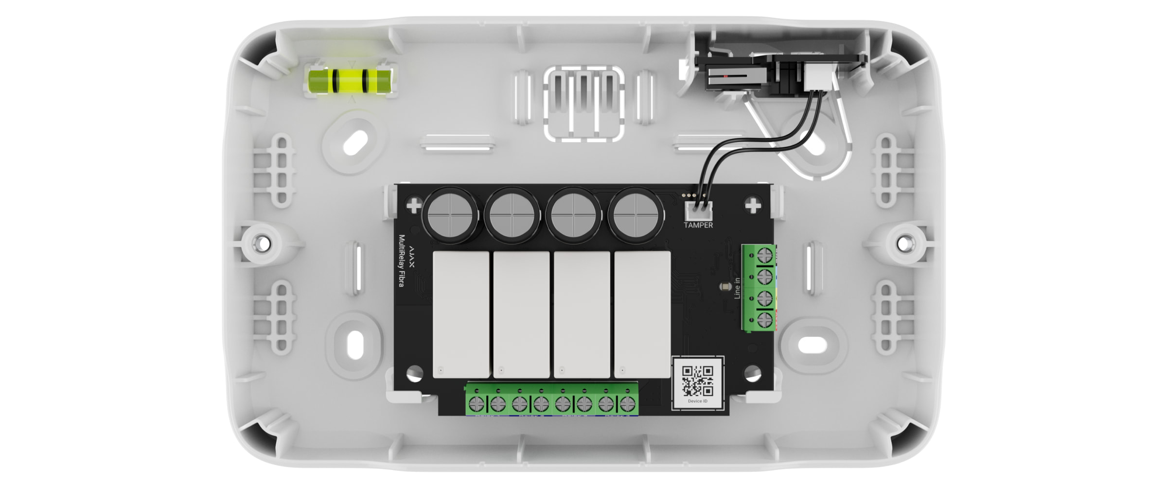
Functional elements
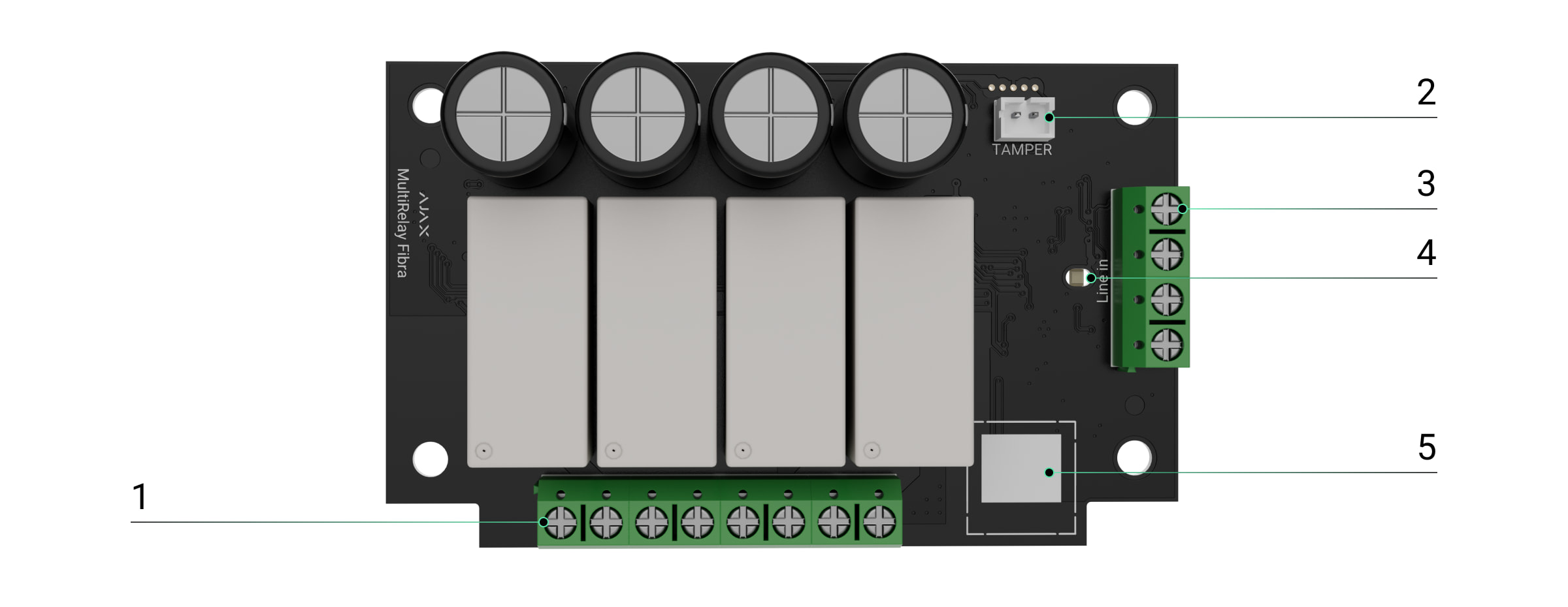
- Relay output terminals.
- Connector to fasten the tamper board to the module. The tamper board is the part of Case that is sold separately.
- MultiRelay input terminals.
- LED indicator.
- QR code with the device ID. It is used to pair this device with an Ajax system.
Operating principle
MultiRelay is a module to control the power supply of electrical appliances remotely. It is used in a wired or hybrid Ajax system. Each of the four relays must be installed in the electrical circuit gap to control the power supply of electrical appliances connected to this circuit. Each of the four relays is configured and controlled separately.
MultiRelay operates as a part of the Fibra line. The module connects to any point of the Fibra line. Electrical appliances connected to the relays are powered separately.
Each relay has potential-free (dry) contacts. Dry contacts are electrically isolated to the relay’s power supply. Thus, this device can be used in low-voltage and household networks, for example, to simulate a button, or a toggle switch, or to control water shut-off valves, electromagnetic locks, irrigation systems, gates, barriers, and other systems.
Each relay’s maximum resistive load is 5 A at 30 V⎓ and 10 A at 110–230 V~.
The relay operates in bistable or pulse mode. When operating in a bistable mode, the relay changes the contact state, and the connected electrical appliance turns on or off. When operating in a pulse mode, the relay changes the contact state for the required duration — from 1 second to 2 hours. Only PROs or users with admin rights in Ajax apps can select the operating mode in the Ajax apps.
Superior MultiRelay Fibra also allows integrating electric lock or third-party blocking element to Ajax system. Blocking element is needed to set up system according to the unavoidability principle (German: Zwangsläufigkeit).
The device has temperature protection. When one of the relays exceeds the permissible temperature, all closed contacts are automatically opened. The switch toggle of the relay that was enabled turns red. The user receives an overheating notification.
The relay functionality is restored when the temperature drops to the permissible level. After power is restored, the relay contacts return to their previous state. If, after the relay has been switched off due to overheating, the user has changed the state using the switch in the application, the contacts will take this state after the temperature returns to normal. When operating in pulse mode, the relay recovers from overheating in the off state.
Automation scenarios
Scenario types with MultiRelay:
- By alarm.
- By security mode change.
- By schedule.
- By pressing Button.
- By temperature.
- By humidity.
- By CO₂ concentraton.
- By touching LightSwitch.
If the device is offline, it will not execute the scenario as it misses the scenario trigger (e.g., during a power outage or when the connection between the hub and device is lost).
Use case: The automated action is scheduled for 10 a.m., so it must start at 10 a.m. The electrical power goes out at 9:55 a.m. and is restored ten minutes later. The automation scenario won’t start at 10 a.m. and will not start immediately after the power is back on. This scheduled action is missed.
Fibra data transfer protocol
The module uses Fibra technology to transmit alarms and events. It is a wired data transfer protocol for fast, reliable two-way communication between the hub and connected devices.
Sending events to the monitoring station
The Ajax system transmits alarms to the PRO Desktop monitoring app, as well as to the central monitoring station (CMS) using SurGard (Contact ID), SIA (DC-09), ADEMCO 685, and other protocols.
MultiRelay can transmit the following events:
- Tamper alarm and turning off the alarm.
- Low supply voltage and voltage return to normal values.
- Loss and restoration of communication between MultiRelay and the hub.
- Permanent deactivation and activation of the device.
- One-time deactivation and activation of the device.
When an alarm is received, the CMS operator knows exactly what happened and where to send the rapid response team. The Ajax devices are addressable, meaning that the PRO Desktop app and CMS receive events, device type, assigned name, and location (room, group). The list of transmitted parameters may differ depending on the CMS type and the selected communication protocol.
The device ID, loop (zone) number, and line number are in the device States.
Selecting the installation site
When choosing a spot to install MultiRelay, consider the parameters that affect the operation of the device:
- Fibra signal strength.
- The length of the cable used to connect MultiRelay.
- The length of the cable used to connect wired devices to MultiRelay.
Follow these recommendations when designing the Ajax system project for an object. Only professionals should design and install the security system. The list of authorized Ajax partners is available here.
Installing into Case
We recommend installing MultiRelay into Case. The casing is sold separately and available in multiple versions. Installing a single module, several modules, or several other devices into Case is possible. Use Case configurator to get the most optimal placement of your Fibra devices in the casing.
Case has mounts for the modules, wire channels, and a tamper that connects to the board of MultiRelay.
MultiRelay cannot be installed
- Outdoors. It can damage the module.
- Inside premises where temperature and humidity values do not correspond to the operating parameters. It can damage the module.
- In places with low or unstable Fibra signal strength.
- Without Case.
Fibra signal strength
Fibra signal strength is the ratio of undelivered or corrupted data packages to those expected over a specific time. The icon ![]() in the Devices
in the Devices ![]() tab in Ajax apps indicates the signal strength:
tab in Ajax apps indicates the signal strength:
- Three bars — excellent signal strength.
- Two bars — good signal strength.
- One bar — low signal strength; stable operation is not guaranteed.
- Crossed out icon — no signal; stable operation is not guaranteed.
Lines Power Test
The test simulates the maximum energy consumption of devices connected to the hub. If the system passes the test successfully, all its devices have enough power in any situation. After the test, the app displays a notification with the status of each line:
- Test passed.
- Test passed with malfunctions.
- Test failed.
Designing the system project
It is crucial to properly design the system project to install and configure the devices correctly. The project must consider the number and types of devices at the object, their exact location and installation height, the length of wired Fibra lines, the cable type, and other parameters. Read the article to learn tips for designing the Fibra system project.
MultiRelay can be connected at any point of the Fibra line. The output line of the device can have a length of up to 2,000 meters when connected using the U/UTP cat.5 twisted pair cable.
Different types of devices can be connected to the relay output terminals. For example, you can connect heaters, humidifiers, electric locks, and lighting devices. Each relay should not be connected to circuits with more than 5 A load at 30 V⎓ and 10 A at 110–230 V~.
Ajax systems also support Beam and Ring topologies.
Cable length and type
Recommended types of cable used to connect MultiRelay to the hub:
- U/UTP cat.5, 4 × 2 × 0.51, copper conductor.
- Signal cable 4 × 0.22, copper conductor.
The wired connection range may vary if you use a different cable type. No other types of cables have been tested.
The cable cross-section for connecting electrical appliances to the relay terminals is selected depending on the current. The recommended cross-section of the cable is no more than 1.5 mm². This limitation is due to the risk of physical damage to the terminals.
Verification using a calculator
We have developed the Fibra power supply calculator to ensure that the project is designed correctly and the system will work in practice. It helps to check the communication quality and cable length for wired Fibra devices when designing the system project.
Preparing for installation
Cable arrangement
When preparing to lay cables, check your region’s electrical and fire safety regulations. Strictly follow these standards and regulations. Tips for cable arrangement are available in the article.
Cable routing
We recommend you carefully read the Selecting the installation site section before installation. Do not deviate from the system project. Violating the basic MultiRelay installation rules and the recommendations of this manual may lead to incorrect operation and loss of connection with the device. Tips for cable routing are available in the article.
Preparing cables for connection
Remove the insulating layer and strip the cable with a special insulation stripper. The ends of the wires inserted into the device terminals must be tinned or crimped with a sleeve. It ensures a reliable connection and protects the conductor from oxidation. Tips for preparing the cables are available in the article.
Installation and connection
Connecting Superior MultiRelay Fibra to the hub
- Prepare cable holes in advance by carefully breaking out the perforated parts of Case.
- Secure Case with the bundled screws using at least two fixing points. Fix Case at a point with a perforated area so its tamper responds to disassembly attempts.
- Turn off the power of lines in the Ajax PRO app:
-
- Hub → Settings
 → Lines → Lines Power Supply.
- Hub → Settings
-
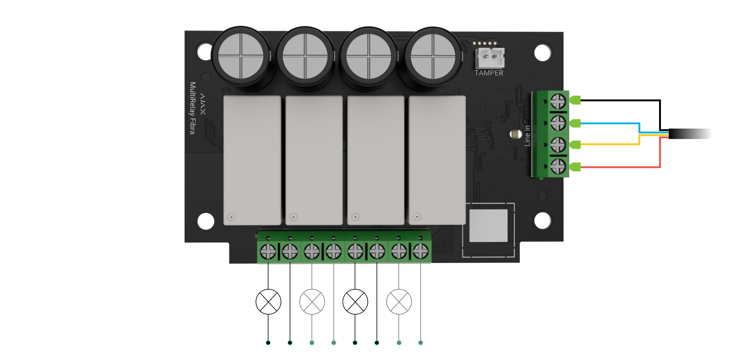
- Route the cable to connect MultiRelay to the hub casing. Connect the wires to the required hub line.
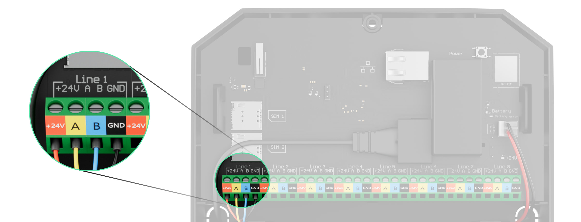
+24V — 24 V⎓ power terminal.
А, B — signal terminals.
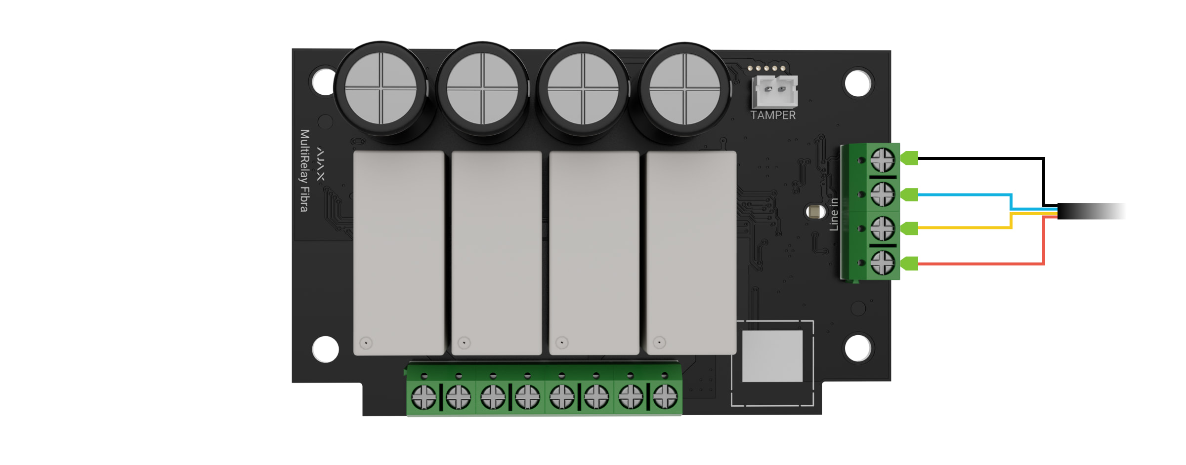
GND — ground. - Connect the wires to the MultiRelay input terminals according to the diagram below. Follow the polarity and connection order of the wires. Securely fasten the cable to the terminals.
- Connect the device’s wires to the relay output terminals.
- Secure the module in Case using holes in the board. Secure the cable with ties.
- Connect the Case tamper to the appropriate module connector.
- Place the lid on the casing and fasten it with the bundled screws.
- Turn on the power supply of lines in the Ajax PRO app:
- Hub → Settings → Lines → Lines Power Supply.
- Hub → Settings
- Add MultiRelay to the hub.
- Run the functionality testing.
Connecting devices to Superior MultiRelay Fibra
- Turn off the power of lines in the Ajax PRO app:
- Hub → Settings → Lines → Lines Power Supply.
- Hub → Settings
- De-energize the power cables that you will connect to the relay.
- Connect the wires to the relay output terminals according to the diagram below. Follow the polarity and connection order of the wires. Securely fasten the cable to the terminals.
- Turn on the power supply of lines in the Ajax PRO app:
- Hub → Settings → Lines → Lines Power Supply.
- Hub → Settings
- Set the necessary relay settings.
Adding to the system
Superior MultiRelay Fibra is compatible only with Superior Hub Hybrid (2G) and Superior Hub Hybrid (4G). Only verified partners can add and configure Fibra devices in Ajax PRO apps.
Before adding a device
- Install an Ajax PRO app.
- Log in to a PRO account or create a new one.
- Select a space or create a new one.

The space functionality is available for apps of such versions or later:
- Ajax Security System 3.0 for iOS;
- Ajax Security System 3.0 for Android;
- Ajax PRO: Tool for Engineers 2.0 for iOS;
- Ajax PRO: Tool for Engineers 2.0 for Android;
- Ajax PRO Desktop 4.0 for macOS;
- Ajax PRO Desktop 4.0 for Windows.
- Add at least one virtual room.
- Add a compatible hub to the space. Ensure the hub is switched on and has internet access via Ethernet, Wi-Fi, and/or mobile network.
- Ensure the space is disarmed, and the hub is not starting an update by checking statuses in the Ajax app.
How to add Superior MultiRelay Fibra
Two ways to add devices are available in the Ajax PRO app: automatically and manually.
- Open the Ajax PRO app. Select the hub to which you want to add Superior MultiRelay Fibra.
- Go to the Devices
 tab and click Add Device.
 - Select Add All Fibra Devices. The hub will scan the Fibra lines. After scanning, all devices connected to the hub that still need to be added to the system will be shown.
- Select the device from the list. After pressing, the LED indicator will flash to identify this device.
- Set the device name, and specify the room and security group if Group Mode is enabled. Press Save.
If the connection fails, check the wired connection’s correctness and try again. If the maximum number of devices (100 for Superior Hub Hybrid) has already been added to the hub, you will receive an error notification while adding.
MultiRelay only works with one hub. The module stops exchanging data with the previous hub when pairing with a new one. When MultiRelay is added to a new hub, it remains in the list of devices on the previous hub. You can remove it manually.
Functionality testing
Available for MultiRelay:
- Fibra Signal Strength Test — to determine the strength and stability of the signal at the device installation site.
- Lines Power Test — to determine if there is enough power for all devices connected to the hub and calibrate the protection threshold.
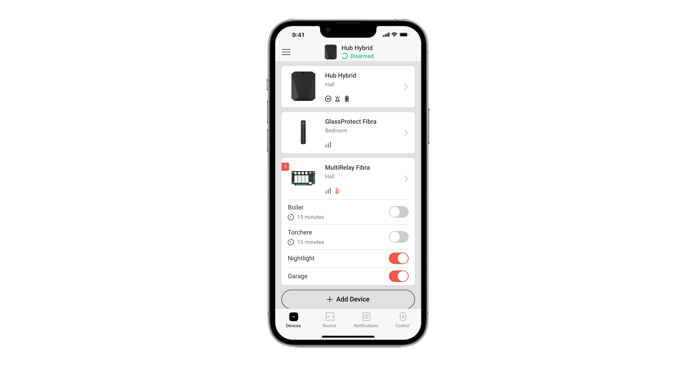
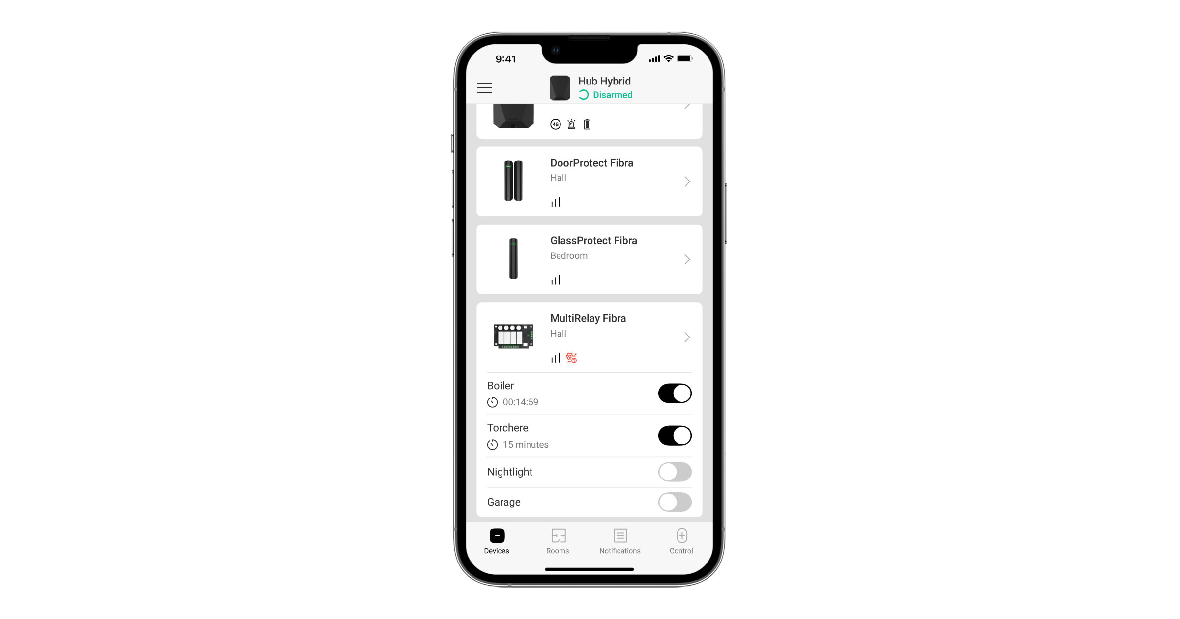
Control via the app
In Ajax apps, a user can switch on and off electrical appliances connected to an electrical circuit controlled by MultiRelay. Click the toggle in the MultiRelay field in the Devices ![]() menu: the state of the relay contacts will change to the opposite, and the connected electrical device will switch off or on.
menu: the state of the relay contacts will change to the opposite, and the connected electrical device will switch off or on.
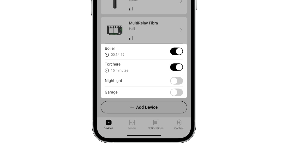
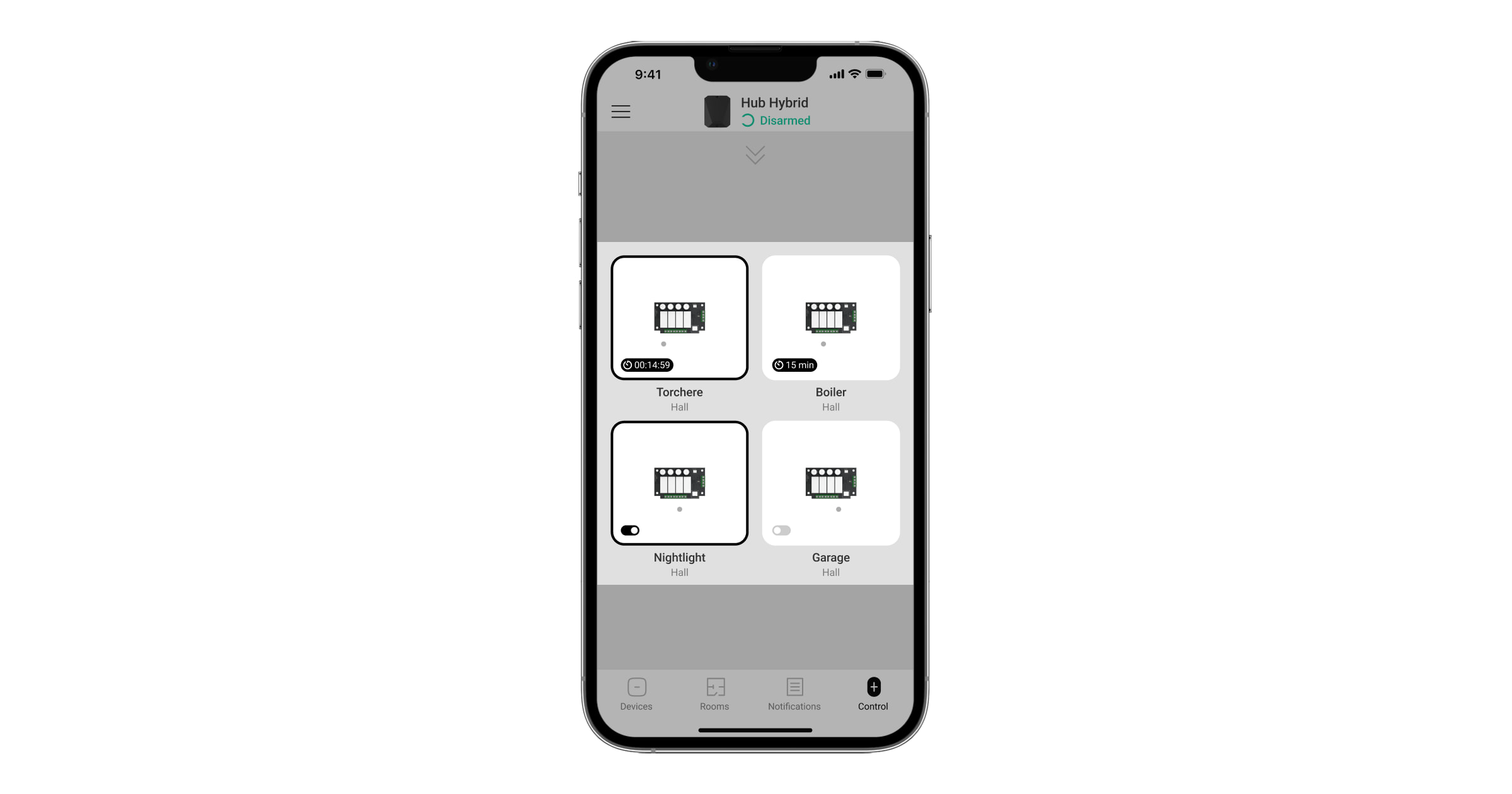
Quick control of automation devices is also available in the Automation Menu. You can open the menu in the Ajax apps:
- Go to the Deviсes tab.
- Select the required hub from the list.
- Go to the Control tab.
- Swipe up.
- Control the required devices.
- Swipe down to return to the Control tab.
Icons
The icons show some statuses of the device. You can check them in the Ajax apps:
- Select a hub in the Ajax app.
- Go to the Devises tab.
- Find MultiRelay in the list.
| Icon | Meaning |
|
Fibra Signal Strength — displays the signal strength between the hub and the module. Recommended values: 2–3 bars. |
|
| A malfunction is detected. | |
|
MultiRelay is permanently deactivated. |
|
|
In MultiRelay, events of tamper triggering are permanently disabled. |
|
| MultiRelay is deactivated for one arming cycle. | |
|
In MultiRelay, events of tamper triggering are disabled for one arming cycle. |
|
| Temperature protection is activated. | |
| The device has lost connection with the hub or the hub has lost connection with the Ajax Cloud server. | |
|
The device has not been transferred to the new hub. |
States
The states display information about the device and its operating parameters. You can check the MultiRelay states in the Ajax apps:
- Select a hub in the Ajax app.
- Go to the Devises tab.
- Select MultiRelay from the list of devices.
| Parameter | Meaning |
| Data import | Displays the error when transferring data to the new hub:
|
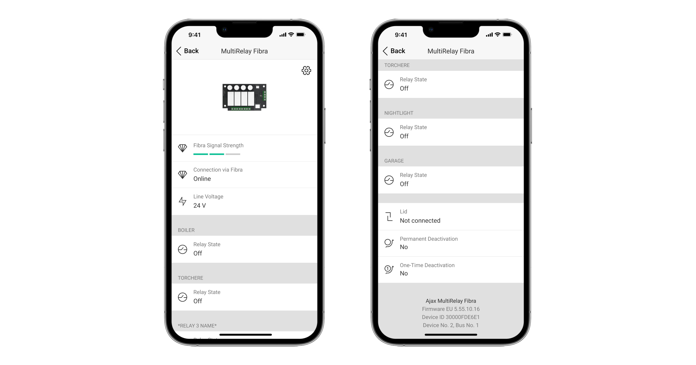
| Fibra signal strength |
Signal strength between the hub and Superior MultiRelay Fibra. Recommended values: 2–3 bars. Fibra is a protocol for transmitting events and alarms. |
| Connection via Fibra | The status of the connection between the hub and the module:
|
| Line voltage | The voltage value on the Fibra line to which the module is connected. |
| Relay state | Shows for each relay that has the Relay option selected as Output mode:
|
| Blocking element state | Status of the blocking element:
This status is displayed if the Blocking element option is selected for relay Output mode. |
| Electric lock state | Status of the electric lock:
This status is displayed if an Electric lock option is selected for relay Output mode. |
| Operating time |
The time during which the device will be switched on. The field is displayed when the device operates in pulse mode (the Shutoff by Timer option is activated). Shows for each relay. |
| Lid | The tamper status that responds to the detachment of the device from the surface or violation of the device’s casing integrity:
|
| Permanent deactivation | Shows the status of the device permanent deactivation function:
|
| One-time deactivation | Shows the status of the device deactivation for one arming cycle function:
|
| Firmware | MultiRelay firmware version. |
| Device ID | MultiRelay ID/Serial Number. Also available on the device board and its packaging. |
| Device No. | MultiRelay loop (zone) number. |
| Line No. | The Fibra line number of the hub to which MultiRelay is connected. |
Settings
To change module settings in an Ajax app:
- Go to the Devises tab.
- Select MultiRelay from the list.
- Go to Settings by clicking on the gear icon .
- Set the required parameters.
- Click Back to save the new settings.
MultiRelay settings
| Settings | Meaning |
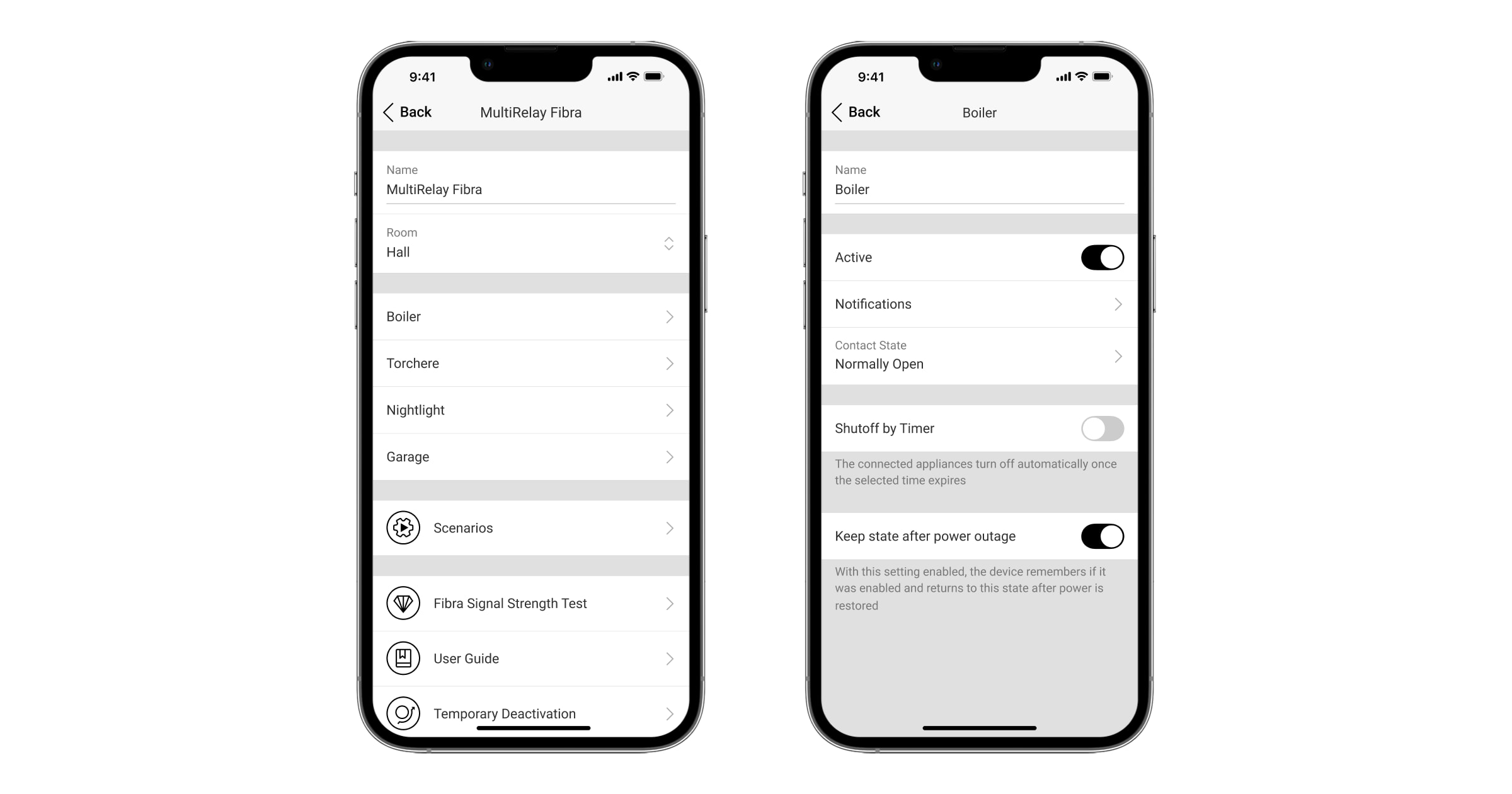
| Name |
Name of the module. Displayed in the list of hub devices, the text of SMS and notifications in the events feed. To change the name of the module, click on the text field. The name can contain up to 12 Cyrillic characters or up to 24 Latin characters. |
| Room |
Selecting the MultiRelay virtual room. The room name is displayed in SMS and notifications in the events feed. |
| <Relay name> | Each relay is configured separately. |
| Scenarios |
Opens the menu for creating and configuring automation scenarios. |
| Fibra Signal Strength Test |
Puts the module into the Fibra Signal Strength Test mode. The test allows you to check the signal strength between the hub and MultiRelay via the wired Fibra data transfer protocol to select the optimal installation site. |
| User Guide | Opens MultiRelay User manual in an Ajax app. |
| Permanent Deactivation |
Allows the user to disable the device without removing it from the system. Three options are available:
|
| One-Time Deactivation |
Allows the user to disable the device for one arming cycle without removing it from the system. Three options are available:
|
| Unpair Device | Unpairs MultiRelay from the hub and deletes its settings. |
Relay settings
| Settings | Meaning |
| Name |
Name of the relay. Displayed in the list of relays, text of notifications in the events feed. To change the name of the relay, click on the text field. The name can contain up to 24 Cyrillic characters or up to 48 Latin characters. |
| Active | When the toggle is enabled, the relay execute system commands and scenarios, and notifies about events. |
| Output mode | Allows the user to select device mode for the connected device:
|
| React to Night mode |
If this option enabled, device will react to Night mode activation/deactivation in the same way as to arming/disarming. This option displayed only when Output mode is set to Blocking element. |
| Notifications | If the Relay option is selected for Output mode it is possible to select the relay notifications:
If the Blocking element or Electric lock is selected for Output mode it is possible to select between the following options:
|
| Contact State | Selecting the normal state of the relay contacts:
|
| Shutoff by Timer | Option for deactivating the controlled device after a set time. If this option is enabled, you need to set a time: from 1 second to 2 hours. |
| Operating Time |
The time during which the device will be switched on. The field is displayed when the device is operating in pulse mode (the Shutoff by Timer option is activated). Sets up from 1 second to 2 hours. |
| Keep state after power outage |
When the toggle is disabled, the relay contacts return to normal in case of a power outage. When the toggle is enabled, the current state of the relay contacts saves in case of a power outage. The option is available for a bistable mode. When operating in a pulse mode, the relay contacts return to normal in case of a power outage. |
| Control of blocking element state | Allows to control blocking element state manually.This option displayed only when Output mode is set to Blocking element. |
Indication
| Event | Indication | Note |
| Adding a module |
When added automatically — the green LED flashes quickly when MultiRelay is selected from the list. When you click Add device, the green LED flashes once. When added manually — the green LED flashes once. |
|
| Removing the module | The green LED flashes six times. | |
| Tamper triggering | The green LED flashes once. | |
| Lines Power Test | The green and red LEDs are glowing continuously during the test. | |
| Low voltage on the output line | The green LED lights up smoothly and goes out smoothly. | A voltage of 10 V⎓ or less is considered low. |
Maintenance
The device does not require maintenance.
Technical specifications
Warranty
Warranty for Limited Liability Company “Ajax Systems Manufacturing” products are valid for 2 years after purchase. Fuse blowing is not a warranty case.
Please contact Ajax Technical Support first if the device does not function correctly. In most cases, technical issues can be resolved remotely.
Contact Technical Support:
Manufactured by “AS Manufacturing” LLC
