
Along with protection against robbery, fire, and flood, the Ajax system allows you to control electrical appliances by automating the security and eliminating routine. We have already written about the features of connecting an electric lock and a security smoke machine to the system. This article will focus on the control of an electrically driven barrier or gate (automatic gate).
Ajax allows opening and closing, as well as control of the gate/barrier power supply:
- via the Ajax app – from anywhere in the world
- via buttons and keypads – at a distance of up to 1300 meters from the hub or radio signal range extender
- by scenario – when changing the arming mode, when an alarm occurs, according to a schedule
In addition, the app will display the history of opening and closing the gate/barrier: relay name, location, time, and date.
What Ajax devices you need to control a gate/barrier
- Hub — to coordinate the operation of system devices
- Relays — for opening and closing gates/barriers and their power management
- Integration modules — for transmitting the gate/barrier opened or closed status to the system in real-time
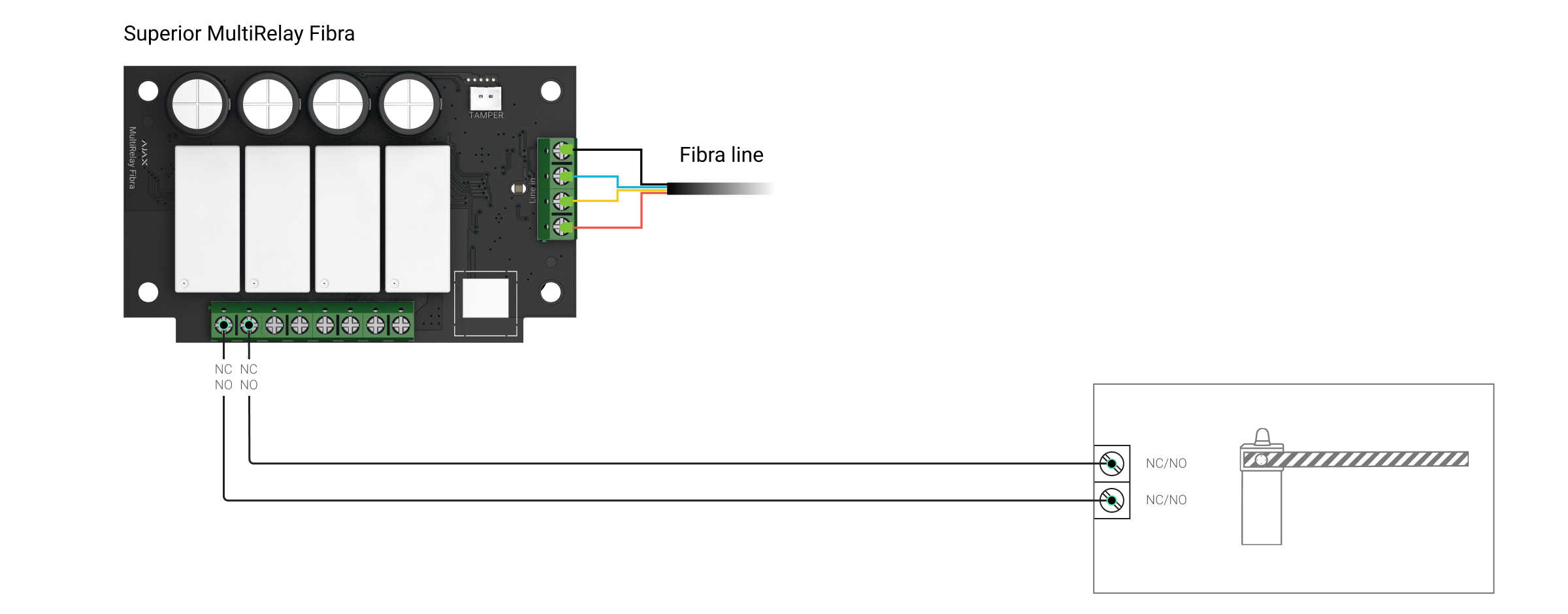
Superior MultiTransmitter IO (4X4) Fibra has inputs that can be used to transmit signals from gate/barriers and outputs to control them.
What gates/barriers can be controlled with Ajax
Modern electrically driven gates and barriers are equipped with a remote control unit. It consists of a controller and control devices such as a remote control. The controller accepts commands from control devices and activates the gate or barrier opening/closing mechanism.
To integrate with Ajax, the controller must have a control input for connecting wired buttons and relays. The absence of such input does not prevent connection, but it greatly complicates the process – you will need to connect the relay directly to the drive or controller board. Also, the controller can have a non-standard control input or special control and operation modes, which should also be taken into account when integrating.
Sending information about the gate/barrier state (“closed” and “opened”) to the Ajax app is possible if the controller has a status output.
Before starting the equipment connection, study the technical documentation of the gate/barrier.
Security requirements
When installing and operating electrical appliances, follow the general electrical safety rules, as well as the requirements of electrical safety regulations.
It is strictly forbidden to disassemble the device that is under voltage. Do not use the device with a damaged power cable.
Relays must be installed and connected by a qualified technician. Do not connect relays to a power supply with voltages that exceed the supported range specified for the device. This is a fire hazard and will damage the device.
During installation, do not allow moisture to penetrate the relays or the cable connections. Consider the operating temperature range and humidity; do not keep the devices outdoors.
When connecting, be sure to refer to the user manual of the barrier/gate. Incorrect connection or setting can lead to inadvertent opening or closing of the gate.
Only close the gate/barrier when nothing prevents it from closing. We recommend supplementing the system with presence IR detectors. The connected presence IR detectors will not allow closing the gate or barrier if a person, car, or another obstacle is in the way of closing.
What to consider before you start connecting a barrier or gate to Ajax
When connected, the Ajax relays will be used: Relay Jeweller, Superior MultiRelay Fibra or Superior MultiTransmitter IO (4X4) Fibra to control the opening/closing of the gate/barrier; WallSwitch Jeweller or Superior MultiRelay Fibra to de-energize the gate/barrier manually or automatically.
The gate/barrier controller can have one or more control inputs. The wiring diagram of the gate/barrier controller depends on this. If the input is combined and is responsible for both opening and closing the gate/barrier, one relay will be enough. Separate inputs (one input responsible for the opening and the other one for the closing) will require two relays.
We also recommend providing all relays with back-up power in case of power outages. Please note that the barrier or gate can operate from a different voltage. In this case, you will have to connect relay to an independent power supply.
If you want the Ajax app to display the gate/barrier status (opened or closed), connect the integration module to the gate/barrier status output on the controller.
We recommend reading user manual of devices used in setup in its entirety before installation. It can provide helpful information for correct configuration and wiring, as well as the user manual provided with the third-party gate/barrier.
How to use Ajax to control the opening and closing of a gate/barrier with a combined control input
Connect the low-current relay of choice to the controller according to the diagrams below and set up the system.
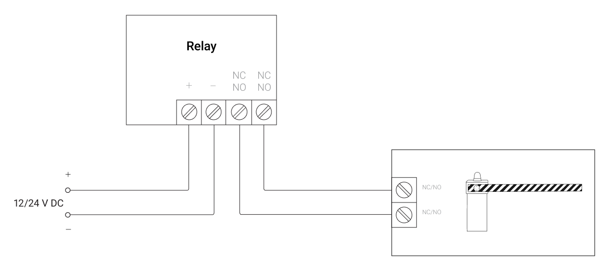
- Connect the power supply source to the power terminals of the relay.
- Connect the relay contact terminals to the control input.
If the Relay Jeweller is connected to a controller that opens the gate on contacts opening, provide the relay with backup power. In the event of a power loss, the Relay Jeweller contacts change to an open state, which will open the gate.
In the Ajax app:
- Go to the Devices
 tab.
tab. - Select Relay Jeweller and go to its Settings
 .
. - Set the required parameters.

The settings depend on your gate/barrier model. See wiring recommendations in the technical documentation of the device.
- Relay operating mode: pulse or bistable.
- Pulse duration (if pulse mode is selected): in the range from 0.5 to 255 seconds. The duration must be greater than or equal to the closing/opening time of the barrier or gate.

An incorrectly selected pulse duration can cause the gate or barrier to close immediately after opening, or open/close incompletely.
- Contact state: normally closed or normally opened.
- Click Back to save the settings.
For more informative notifications, rename Relay Jeweller. For example, name the device “Entrance Gate”.
How to use Ajax to control the opening and closing of a gate/barrier with separate control inputs
Connect the low-current relays to the controller according to the diagram below and set up the system. With this wiring diagram, one relay controls the opening, and the other the closing.
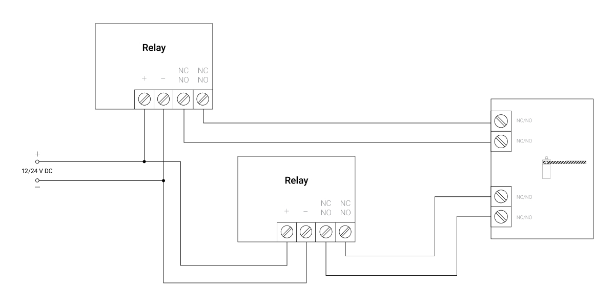
- Connect the power supply source to the power terminals of the relay.
- Connect the contact terminals of the first relay to the first control input.
- Connect the contact terminals of the second relay to the second control input.
In the Ajax app:
- Go to the Devices tab.
- Select the first Relay Jeweller and go to its Settings .
- Set the required parameters.
The settings depend on your gate/barrier model. See wiring recommendations in the technical documentation of the device.
- Relay operating mode: pulse or bistable.
- Pulse duration (if pulse mode is selected): in the range from 0.5 to 255 seconds. The duration must be greater than or equal to the closing/opening time of the barrier or gate.
- Contact state: normally closed or normally opened.
- Click Back to save the settings.
- Repeat steps 1-4 for the second Relay Jeweller.
For more informative notifications, rename Relay Jeweller. For example, name the device connected to the first control input “Open gate”, and the device connected to the second one “Close gate”.

How to control gate/barrier power supply using Ajax
The power control will work in parallel with the gate/barrier opening/closing control. Connect the WallSwitch Jeweller or Superior MultiRelay Fibra to the controller power circuit according to the diagrams below and configure the system.
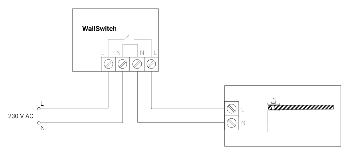
- Connect the power supply source to the power terminals of WallSwitch Jeweller.
- Connect the relay contact terminals to the gate/barrier power inputs.
In the Ajax app:
- Go to the Devices tab.
- Select WallSwitch Jeweller and go to its Settings .
- Set the required parameters.
The settings depend on your gate/barrier model. See wiring recommendations in the technical documentation of the device.
- Relay operating mode: bistable.
- Contact state: normally closed or normally opened.
- Click Back to save the settings.
Rename WallSwitch Jeweller for more informative notifications. For example, name the device “Gate power”.

How to control the closing/opening of a gate/barrier
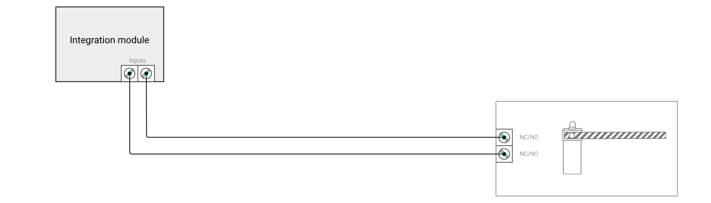
To display the gate/barrier status (opened or closed) in the Ajax app, connect the integration module to the gate/barrier controller status output.
Connect the status output of the gate/barrier controller to the tamper or alarm terminals of Transmitter Jeweller. The algorithm of work depends on this.
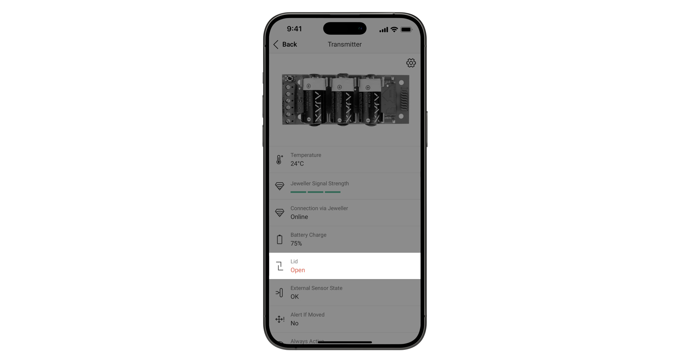
When connected via Transmitter Jeweller tamper terminals, the security system notifies about opening and closing regardless of the security mode. The gate/barrier state is displayed in real-time in the Lid field in the Transmitter Jeweller states (Ajax app – Devices – Transmitter Jeweller).
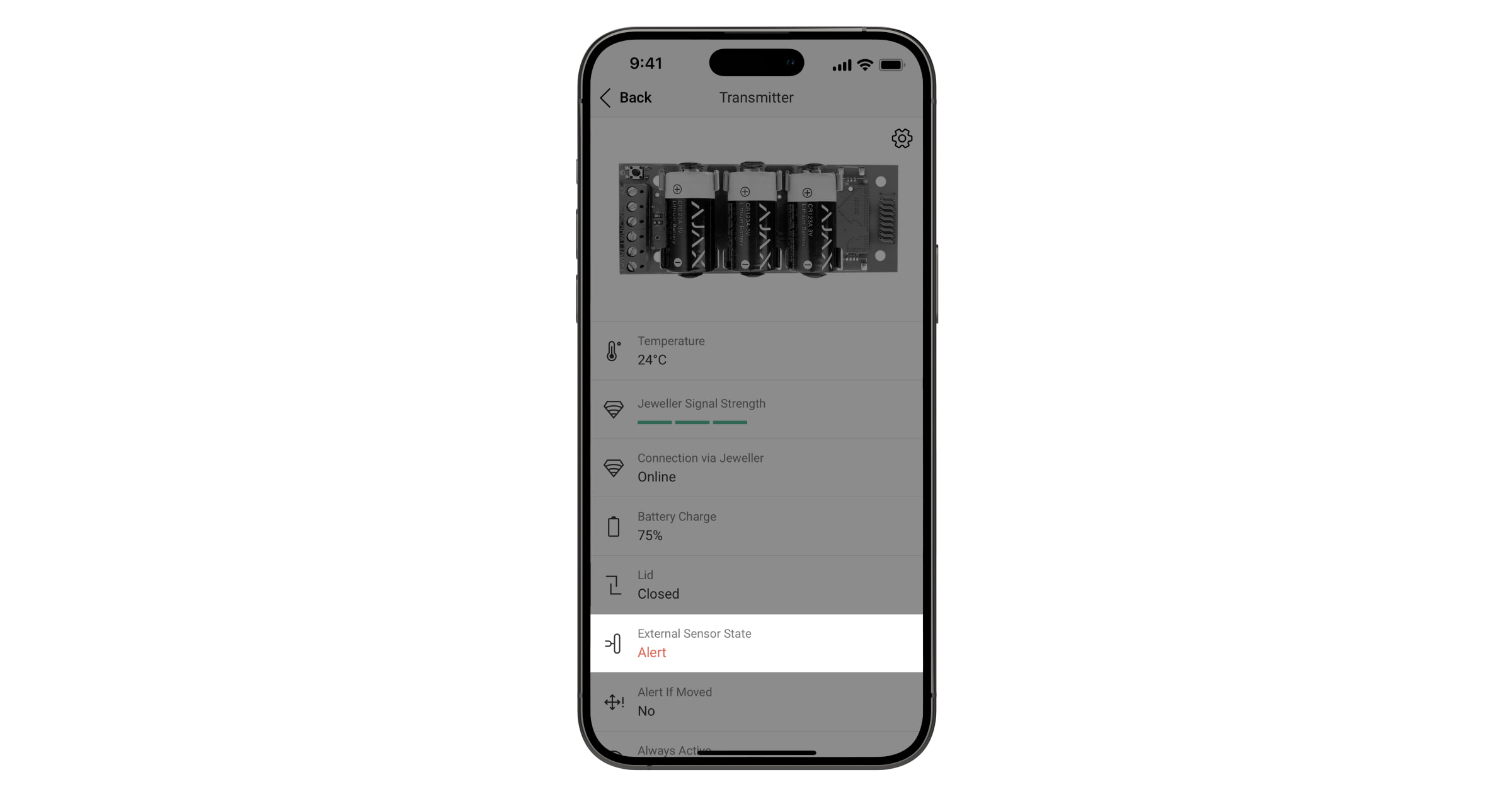
When connected via Transmitter Jeweller alarm terminals, the system notifies about opening and closing only when it is armed. Exception – Transmitter Jeweller operates in the Always Active mode. The gate/barrier status is displayed in real-time in the Detector status field, in the Transmitter Jeweller states (Ajax app – Devices – Transmitter Jeweller).
In the Ajax app:
- Go to the Devices tab.
- Select Transmitter Jeweller and go to its Settings .
- Set the required parameters.
The settings depend on your gate/barrier model. See wiring recommendations in the technical documentation of the device.
- External detector contact status (if using alarm terminals): normally closed or normally opened.
- External detector type (if alarm terminals are used): pulse or bistable.
- Tamper status (if tamper terminals are used): normally closed or normally opened.
- Activate Alert if Moved if you want to receive an alarm event when trying to move Transmitter Jeweller (using the built-in accelerometer).
- Specify the activation settings for the sirens connected to the hub: enable or disable.
- Click Back to save the settings.
For more informative notifications, rename Transmitter Jeweller. For example, name the device “Gate state”.
How to control a gate or barrier via the Ajax app
Opening/closing when connected to a controller with combined control input
Press the switch in the low-current relay that is connected to gate/barrier– the state of the contacts will change to the opposite, and the gate/barrier will open or close.
If an integration module is connected to the gate/barrier status output, its status menu will show the opened or closed status.
Opening/closing when connected to a controller with separate control inputs
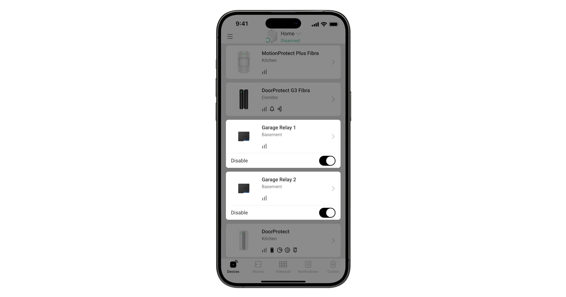
To open the gate/barrier, press the toggle switch in the corresponding low-current relay. For closing, use a similar toggle switch in the second low-current relay.
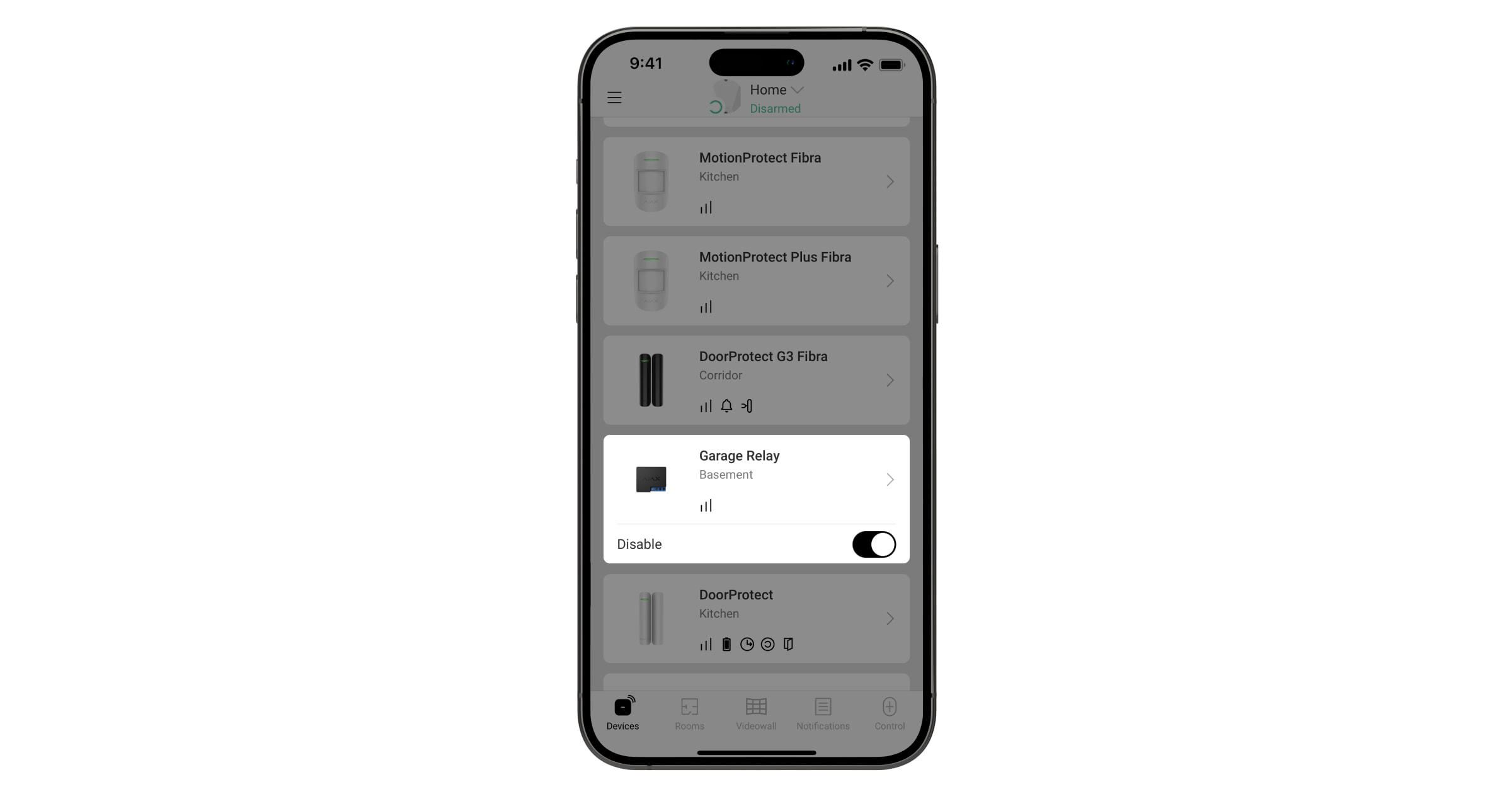
Power control
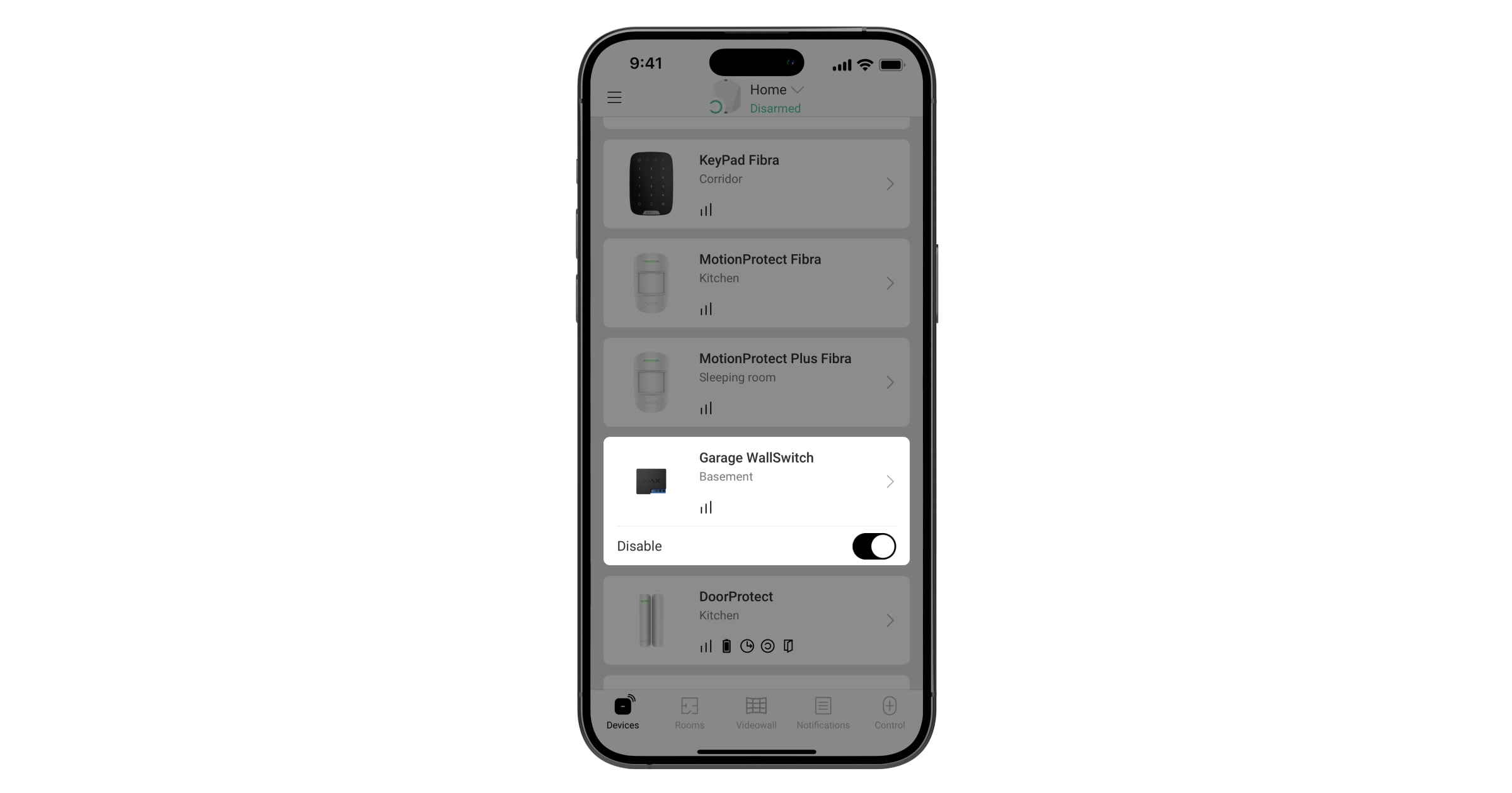
Press the toggle switch in the power relay field, and the state of the contacts will change to the opposite. When the contacts are closed, power is supplied to the device and the gate/barrier can be controlled. When the contacts are open, the power supply to the device is cut off and the gate/barrier is locked.
How to control a gate or barrier using Button Jeweller
The hub with OS Malevich version 2.10 and later allows you to configure different actions for short and long pressing of Button Jeweller. For example, a short press to open/close a gate/barrier, and a long press to de-energize the device.
To control the gate/barrier using Button Jeweller, configure the appropriate scenarios in the menu: Ajax app → Devices ![]() → Button Jeweller → Settings
→ Button Jeweller → Settings ![]() → Scenarios.
→ Scenarios.
How to control a gate or barrier automatically according to scenarios
Ajax scenarios allow you to open and close, as well as supply power and de-energize the gate/barrier when changing the security mode, enabling and disabling the Night mode, by alarm and on schedule.
To create scenarios for gate/barrier control, go to the menu: Ajax app → Devices ![]() → select the corresponding relay → Settings
→ select the corresponding relay → Settings ![]() → Scenarios.
→ Scenarios.