For an Ajax system to comply with the UL requirements, it is necessary to configure some features. For correct setup, follow the step-by-step instructions in the article.
System configuration
The UL certified system consists of the following features and compatible devices.
| Hub models | Hub 2 Plus (9NA) and Hub 2 (4G) (9NA) |
| Power supply | 120–240 V~, 60 Hz, up to 0.083 A (10 W)
Do not connect devices to a receptacle controlled by a switch. |
| Backup battery | Rechargeable Li-ion Polymer Battery XK 953580 3.7 V⎓, 3 Ah The battery used in this device may present a risk of fire or chemical burn if mistreated. Do not disassemble, crush, puncture, heat, burn, or reuse. Replace battery with UL Recognized, Dongguan Lean Power New Energy Technology Co., Ltd., model XK953580 only. Use of another battery may present a risk of fire or explosion. Dispose of used battery promptly. Keep away from children. Do not disassemble and do not dispose of in fire. |
| Firmware | Hub 2 Plus (9NA) — NA 2.X.X and higher Hub 2 4G (9NA) — NA 2.X.X and higher |
| Basic kit |
* required for UL985. |
Compatible devices
| Device | Production | Certificate |
| MotionProtect (9NA) | NA 5.56 and higher | 5.56.X.X |
| MotionProtect Plus (9NA) | NA 5.56 and higher | 5.56.X.X |
| CombiProtect (9NA) | NA 5.56 and higher | 5.56.X.X |
| DoorProtect (9NA) | NA 5.56 and higher | 5.56.X.X |
| DoorProtect Plus (9NA) | NA 5.57 and higher | 5.57.X.X |
| GlassProtect (9NA) | NA 5.56 and higher | 5.56.X.X |
| LeaksProtect (9NA) | NA 5.56 and higher | 5.56.X.X |
| SpaceControl (9NA) | NA 5.56 and higher | 5.56.X.X |
| KeyPad (9NA) | NA 5.57 and higher | 5.57.X.X |
| KeyPad Plus (9NA) | NA 5.57 and higher | 5.57.X.X |
| KeyPad Combi (9NA) | NA 5.57 and higher | 5.57.X.X |
| StreetSiren (9NA) (RFM66) | NA 5.56 and higher | 5.56.X.X |
| StreetSiren (9NA) RFM66A | NA 6.56 and higher | 6.56.X.X |
| StreetSiren DoubleDeck (9NA) RFM66 | NA 5.56 and higher | 5.56.X.X |
| HomeSiren (9NA) RFM66 | NA 5.56.3.33 (UL) and higher | 5.56.X.X |
| Transmitter (9NA) | NA 5.56 and higher | 5.56.X.X |
| MotionProtect Outdoor (9NA) | NA 5.57 and higher | 5.57.X.X |
| MotionProtect Curtain (9NA) | NA 6.58 and higher | 6.58.X.X |
| Button (9NA) | NA 5.56 and higher | 5.56.X.X |
| MotionCam (9NA) | NA 6.58 and higher | 6.58.X.X |
| DualCurtain Outdoor (9NA) | NA 5.56 and higher | 5.56.X.X |
| MotionCam Outdoor (9NA) | NA 5.56 and higher | 5.56.X.X |
| ReX (9NA) | NA 2.15 and higher | 2.X.X |
| ReX 2 (9NA) | NA 2.15 and higher | 2.X.X |
System settings
All the following settings must be configured in PRO apps with access to the system settings. If you don’t have extended access or if it has expired, make a request to the hub owner. To do this, go to Devices ![]() tab and click the
tab and click the ![]() icon in the upper right corner of the screen. Select the time interval you need.
icon in the upper right corner of the screen. Select the time interval you need.
Test the system once a week.
How to set alarm duration
The alarm duration should be set in accordance with the following standards:
| Standard name | Alarm duration |
| UL1023 | 4 min |
| UL985 | 4 min |
| UL2610 | 15 min |
To change the siren settings in Ajax PRO app:
- Go to the Devices
 tab.
tab. - Select the siren from the list.
- Go to Settings by clicking the gear icon
 .
. - Click Alarm Duration and set the duration in accordance with the standard that you need.
- Click Back to save the new settings.
How to disable force arming
Arming the system with malfunctions should be disallowed. You cannot activate the armed mode if the system integrity is violated. For example, a window is open in the protected facility. To arm the system, you should eliminate the malfunction first.
To disable force arming in Ajax PRO app:
- Go to:
- Hub → Settings → Service → System Integrity Check.
- Hub → Settings
- If the toggle is disabled, turn it on.
- Disable the Arming Permission toggle.
- Click Back to save the settings.
How to set exit/entry delay
Delay When Entering (delay in raising the alarm) is the time you have to disarm the security system after entering the premises.
Delay When Leaving (delay in raising the alarm) is the time you have to leave the premises after arming the security system.
In accordance with UL standards:
- Maximum exit delay does not exceed 45 s.
- Maximum entry delay does not exceed 60 s.
To set a delay when entering/leaving, in Ajax PRO app:
- Select the required hub.
- Go to the Devices tab.
- Select the required device or detector on which you want to set the alarm delay.
- Go to settings by clicking the gear icon in the upper right corner.
- Specify Entry/Exit in the Operating Mode of the alarm reaction.
- Specify the required parameters in the fields:
- Delay When Entering.
- Delay When Leaving.
- Enable the toggle Arm in Night Mode.
- Specify the required parameters in the fields:
- Night Mode Delay When Entering.
- Night Mode Delay When Leaving.
- Click Back to save the settings.
For sirens to notify about delays when entering/leaving, in Ajax PRO app:
- Select the required hub if you have several of them or if you are using PRO app.
- Go to the Devices tab.
- Select the required siren.
- Go to settings by clicking the gear icon in the upper right corner.
- Go to the Beeps Settings menu.
- Specify the required parameters in the Beep on delays menu:
- Entry Delays
- Exit Delays
- Entry Delays in Night Mode
- Exit Delays in Night Mode
- Click Back to save the settings.
Installation requirements
Hubs and other devices should be installed in accordance with the following:
- NFPA 70 — National Electrical Code (burglary apps).
- NFPA 72 — National Fire Alarm and Signaling Code (Chapter 2, Fire apps).
- ANSI/NFPA 72 — National Fire Alarm and Signaling Code (Chapter 29).
- CSA C22.1, Canadian Electrical Code, Part I, Safety Standard for Electrical Installations.
- UL 1641, Installation and Classification of Residential Burglar Alarm Units.
- CAN/ULC-S540 — Standard for the Installation of Residential Fire Warning Systems.
- CAN/ULC-S310 — Standard for the Installation and Classification of Residential Burglar Alarm Systems.
- National Building Code of Canada.
- Manufacturer’s installation manual.
- CAN/ULC S302, Standard for the Installation, Inspection and Testing of Intrusion Alarm Systems.
- CAN/ULC S301, Standard for Signal Receiving Centre Intrusion Alarm Systems and Operations.
Installation of an outside alarm device shall be governed by the Standard for Installation and Classification of Burglar and Holdup Alarm Systems, UL 681.
Burglar-alarm systems are classified by type of system. The types of systems covered by these requirements include central station, mercantile, bank, proprietary, and national industrial security systems. Requirements for residential burglar alarm systems are covered in UL 1641, the Standard for Installation and Classification of Residential Burglar Alarm Systems.
Printed information describing proper installation, operation, testing, maintenance, evacuation planning, and repair service is to be provided with this equipment.
Owner’s instruction notice: “Not to be removed by anyone except occupant”.
The system should be checked by a qualified technician at least once every 3 years.
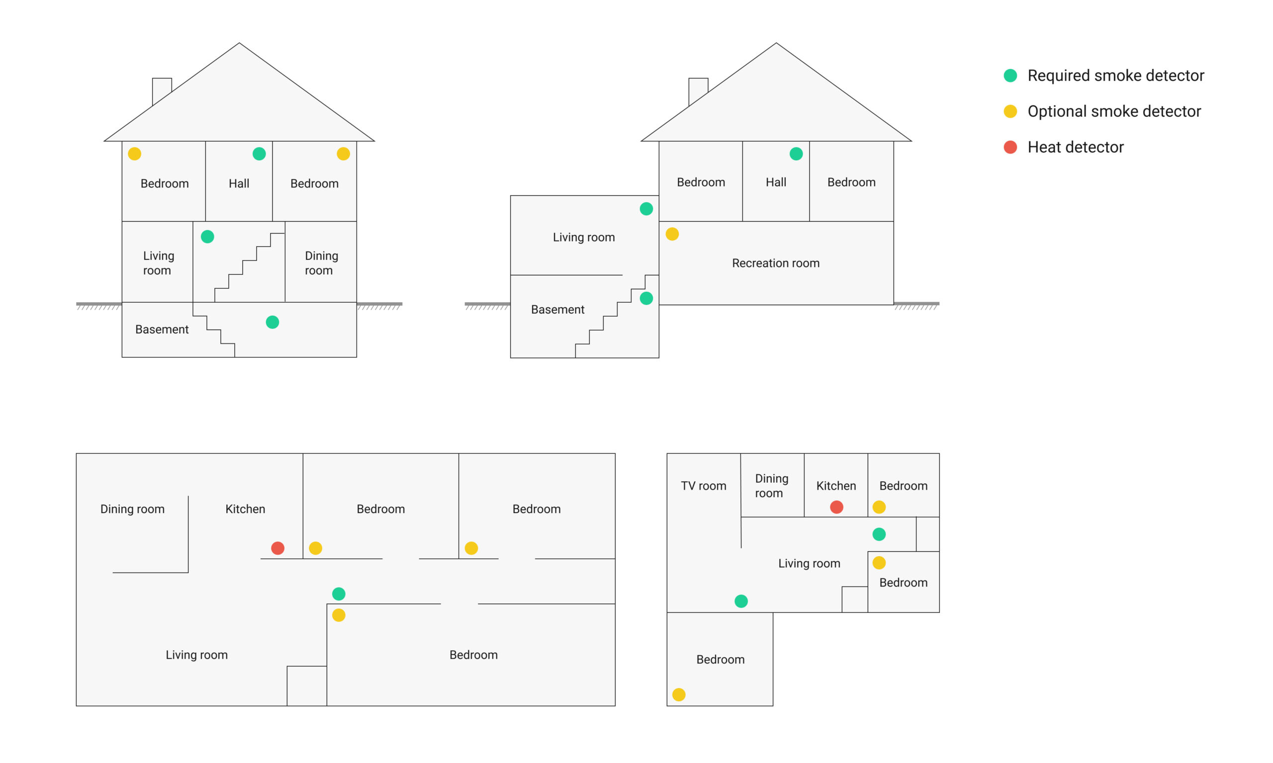
Smoke and heat detector locations
Selecting a suitable location is critical to the operation of smoke alarms. The figure shows some typical floor plans with recommended smoke and heat detector locations.
Follow these location guidelines to optimize performance and reduce the chance of false alarms:
- Before mounting alarms, program them into memory and perform a sensor test from the intended location to ensure reliable RF communication with the panel.
- Locate the alarm in environmentally controlled areas where the temperature range is between 40 and 100°F (5 and 38°C) and humidity is between 0 and 90% non-condensing.
- Locate alarms away from ventilation sources that may hinder the detection of smoke.
- Locate ceiling-mounted alarms in the center of the room or hallway, ensuring a minimum distance of 4 in (10 cm) from any walls or partitions.
- Locate wall-mounted alarms with the top of the alarm situated between 4 to 12 in (10 to 31 cm) below the ceiling.
- In rooms with sloped, peaked, or gabled ceilings, locate alarms 90 cm down or away from the highest point of the ceiling.
- When mounting alarms on suspended ceiling tiles, ensure that the tiles are securely fastened with appropriate methods to prevent displacement.
Do not mount the alarm to the metal runners of suspended ceiling grids. The metal runners can redirect the magnetic field of the alarm’s reed switch, leading to false tamper alarms.
Sending events to the CMS
There are four ways to transmit alarms to the central monitoring station (CMS):
- Via PRO Desktop app.
- Via Ajax Translator app.
- Via Cloud Signaling service (integrated into PRO Desktop app).
- A direct connection.
The Ajax system can transmit alarms to PRO Desktop monitoring app, as well as to the central monitoring station (CMS) using SurGard (Contact ID), SIA (DC-09), ADEMCO 685, and other protocols.
When an alarm is received, the monitoring station operator of the security company knows what happened and where the rapid response unit has to be sent. The Ajax devices addressability allows you to transmit events, device type, its assigned name, and location (room, group) to PRO Desktop and the CMS. The list of transmitted parameters may differ depending on the CMS type and the selected communication protocol.