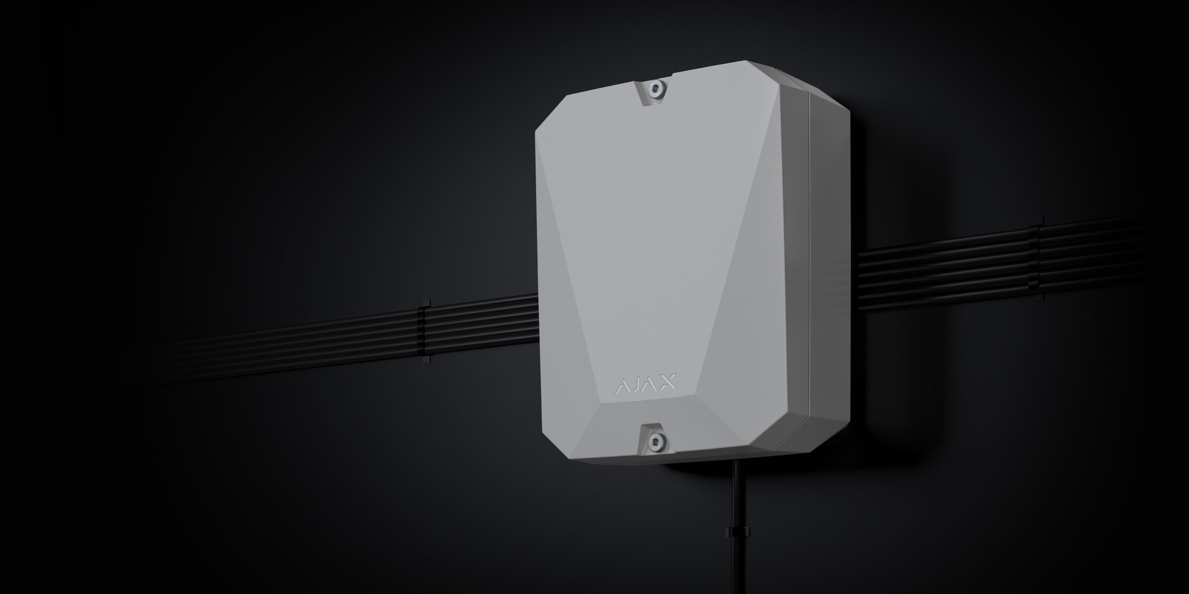
vhfBridge Jeweller is a module for connecting Ajax security systems to third-party VHF transmitters. It provides 8 transistor outputs for connection to third-party VHF transmitters.
The device is powered from 100–240 V~ mains and can be operated from a 12 V⎓ backup battery.
vhfBridge Jeweller operates as part of the Ajax security system and connects to the hub via the Jeweller secure radio communication protocol. The hub communication range is up to 1,800 meters without obstacles. Supplied in two configurations: with a casing and without it.
Functional elements
Casing elements
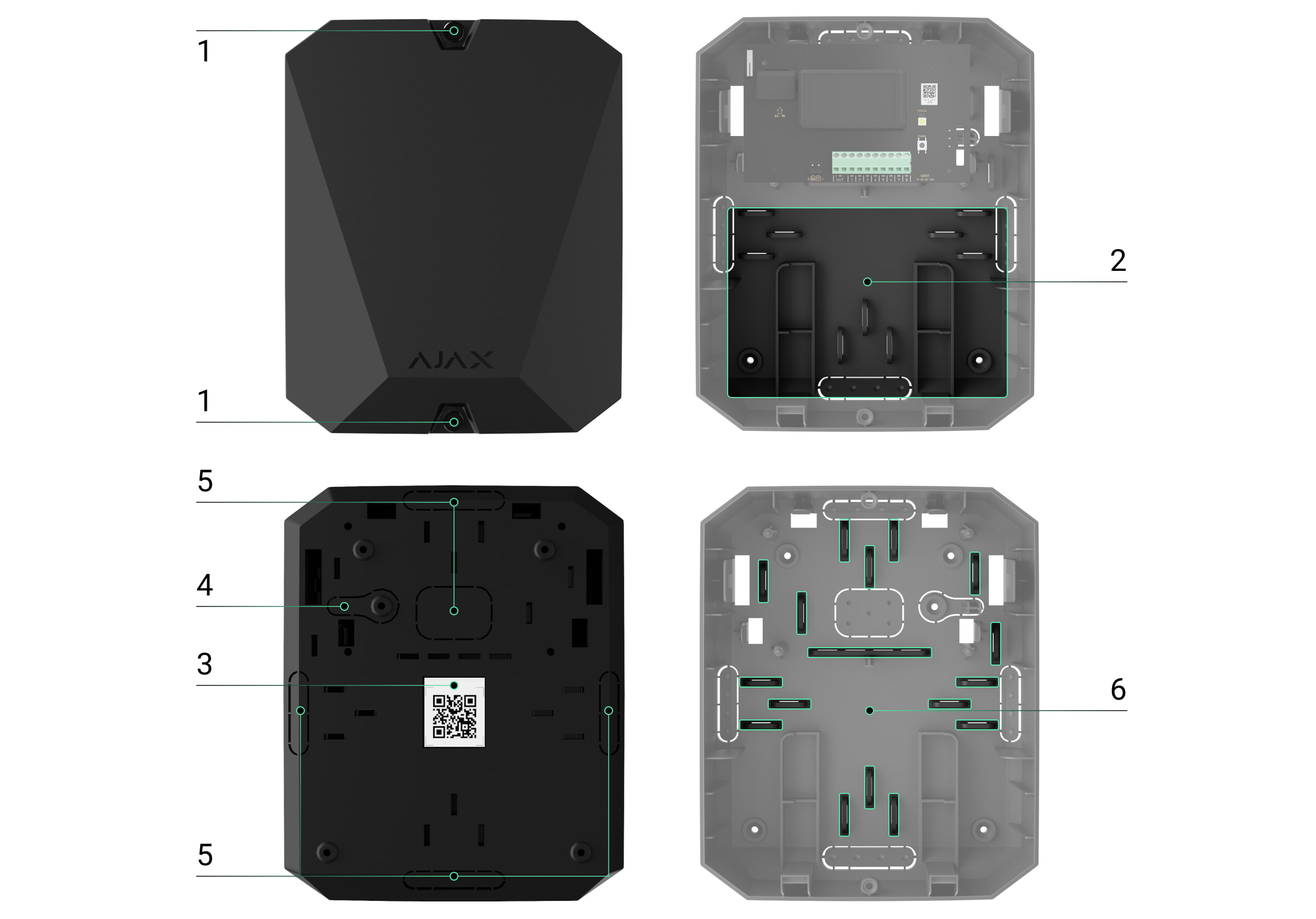
- Screws securing the casing lid. Unscrew with a bundled hexagon key (Ø 4 mm).
- Space for a 12 V⎓ backup battery.

Battery not included with vhfBridge Jeweller set.
- QR code with the device ID. It is used to pair the device with the Ajax security system.
- Perforated part of the casing. Necessary for tamper triggering in case of any attempt to detach the device from the surface.
- Perforated parts of the casing for cable output.
The presence of the casing depends on the vhfBridge Jeweller package. The device is supplied in two configurations: with a casing and without it.
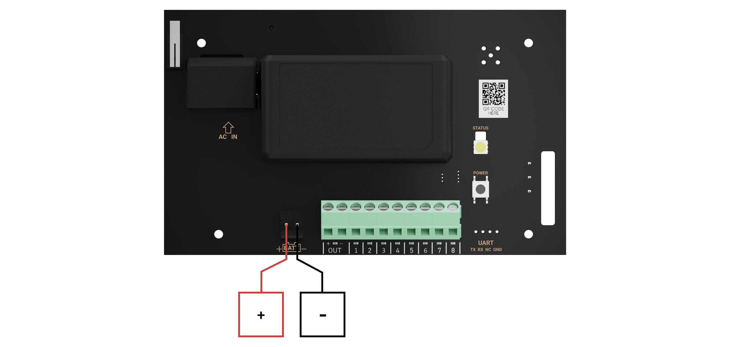
vhfBridge Jeweller board elements
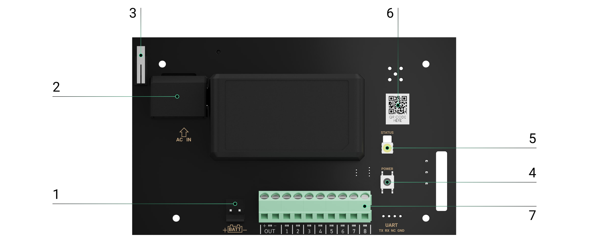
- Terminals for connecting a 12 V⎓ backup battery.
- 100–240 V~ power supply input.
- Tamper button. Signals if vhfBridge Jewellercasing lid is removed.
- Power button.
- LED indicator.
- QR code with the device ID. It is used to pair the device with the Ajax security system.
- Terminals for connecting a VHF transmitter.
vhfBridge Jeweller terminals

- BATT — input for the 12 V⎓ backup power connection.
- OUT — power output for the 12 V⎓ VHF transmitter (maximum output current is 2 A).
- OUT 1…8 — vhfBridge Jeweller outputs for connecting a VHF transmitter.
LED indication
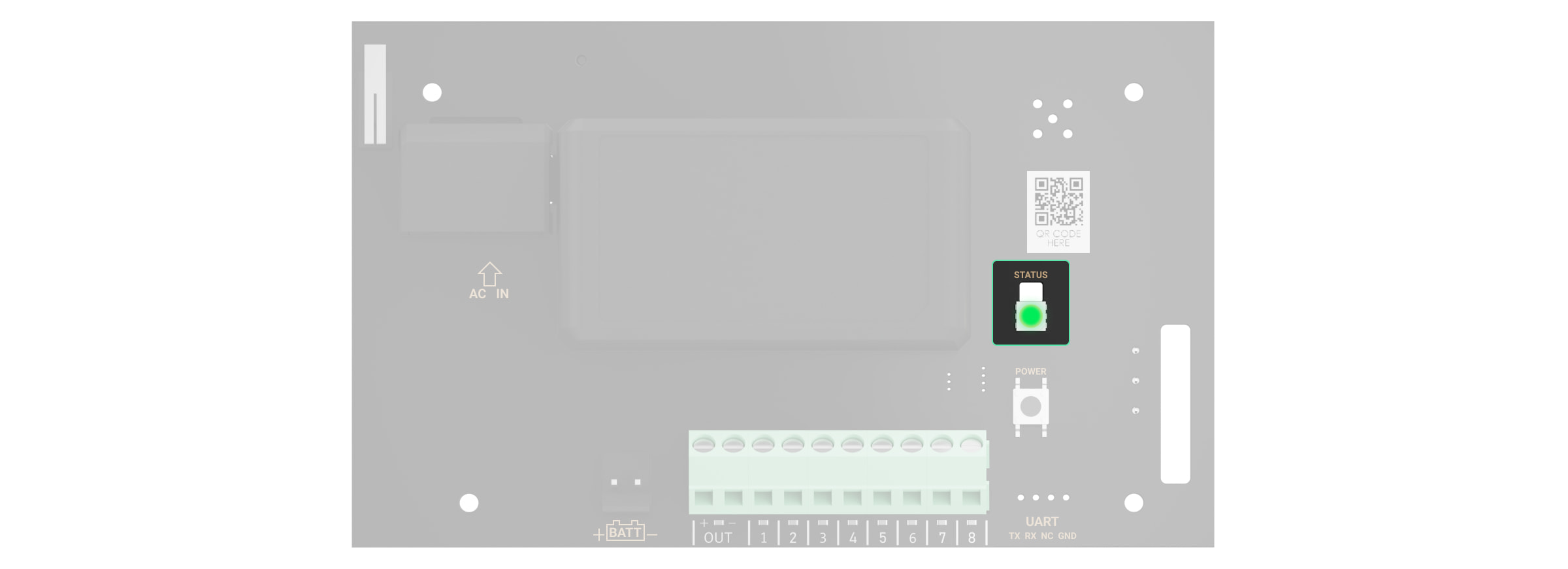
vhfBridge Jeweller LED indicator may light up white, red, or green, depending on the status of the device.
Please note that the LED indicator is not visible when the casing lid is closed. The LED indicator is used at the stage of vhfBridge Jeweller connecting and configuring. Later on, the state of the device can be monitored in the Ajax app.
| LED indication | Event | Note |
| Lights up white. | Connection with the hub is established, external power supply is connected. | |
| Lights up red. | There is no connection with the hub, external power supply is connected. | For example, the hub is turned off or vhfBridge Jeweller is outside the coverage area of the hub’s wireless network. |
| Goes out for 0.5 seconds, then lights up green and turns off. | Enabling vhfBridge Jeweller. | |
| Goes out for 0.5 seconds, then lights up green and fades out over 3 seconds. | Disabling vhfBridge Jeweller. | |
| Blinks red once per second. | vhfBridge Jeweller is not assigned to a hub. | |
| Lights up for a second once every 10 seconds. | No external power supply is connected to vhfBridge Jeweller. | The colour of the indication depends on the status of connection with the hub:
|
| During an alarm, gradually lights up and goes out once every 10 seconds. | No external power supply and discharged external battery of vhfBridge Jeweller. | The colour of the indication depends on the status of connection with the hub:
|
LED indication of output status
| LED indication | Output status in case of alarm |
| High potential output (positive trip). | Lights up green. |
| Low potential output (negative trip). | Goes out. |
Operating principle
vhfBridge Jeweller is designed to connect third-party VHF transmitters to create an additional channel for transmitting events to the CMS.
The communication channel with the CMS created using vhfBridge Jeweller can be used as the only or as a backup channel for communicating with the CMS (recommended more reliable option). This means that the hub can simultaneously transmit all events and alarms to the monitoring station of the security company not only through SIA (DC-09), ADEMCO 685, SurGard (Contact ID), and other proprietary protocols but also using vhfBridge Jeweller.
The transponder receives information about alarms and events from the hub via the Jeweller radio channel. Then, vhfBridge Jeweller transmits it to a third-party VHF transmitter via wires. The VHF transmitter, in turn, transmits all events and alarms to the CMS via a radio channel.
Events can be transmitted to the CMS via the Internet and vhfBridge Jeweller in parallel. Transmission via the Internet works as the main channel because of greater reliability and informativity. The transmitted events may contain the zone number of the triggered detector, group number, user number, and other data.
vhfBridge Jeweller works as a backup communication channel duplicating all events transmitted via the Internet. The delivery speed of events and alarms in both cases does not exceed 1 second.
An example of the algorithm of actions in case of an alarm from a MotionProtect motion detector:
- MotionProtect has detected an alarm.
- MotionProtect transmits the alarm to the hub via the Jeweller radio protocol.
- The hub receives the MotionProtect alarm and transmits it to vhfBridge Jeweller via the Jeweller radio protocol.
- vhfBridge Jeweller receives the alarm from the hub and transmits it to the VHF transmitter over a wired connection.
- The VHF transmitter receives the alarm and transmits it to the radio receiver on the CMS side via the radio channel.
- The radio receiver receives the alarm and transmits it to the CMS software.
- The CMS receives and processes the alarm.
Output types
vhfBridge Jeweller has 8 potential outputs for connection to a VHF transmitter. There are two types of outputs:
- High potential output (positive trip).
- Low potential output (negative trip).
The high-potential output does not supply voltage in the normal state. As soon as an alarm or event occurs, the output supplies a voltage of 12–14 V⎓. The low-potential output works the other way around. In the normal state, the voltage is maintained at 12–14 V⎓, and when an alarm or event occurs, it drops to 0 V.
The vhfBridge Jeweller output type and alarm pulse duration are configurable in Ajax apps.
VHF transmitter power supply
vhfBridge Jeweller can supply a third-party VHF transmitter with 12 V⎓ power (maximum output current is 2 A).
If the VHF transmitter has a current consumption of more than 2 A, it can be powered by the vhfBridge Jeweller battery. In this case, disable battery charge tracking in the vhfBridge Jeweller settings so that the system users do not receive notifications about the vhfBridge Jeweller battery charging too long.
Sending events to the Central Monitoring Station (CMS)
The Ajax security system can transmit alarms to the PRO Desktop monitoring app as well as the Central Monitoring Station (CMS) using SurGard (Contact ID), SIA DC-09 (ADM-CID), ADEMCO 685, and other proprietary protocols. The list of supported protocols is available here.
When an alarm is received, the monitoring station operator of the security company knows what happened and where the rapid response unit has to be sent. All Ajax devices are addressable, so events, the device type, its assigned name and room can be transmitted to the PRO Desktop and the CMS. The list of transmitted parameters may differ depending on the type of the CMS and the selected communication protocol.
You can find vhfBridge Jeweller ID and zone number in the States in Ajax apps. The device number corresponds to the loop (zone) number.
Adding to the system
vhfBridge Jeweller doesn’t work with Hub, ocBridge Plus, uartBridge and third-party security central units. The device can only be added and configured through the Ajax PRO app by a user with administrator rights.
Before adding a device
- Install the Ajax app.
- Log in to your account or create a new one.
- Select a space or create a new one.
The space functionality is available for apps of such versions or later:
- Ajax Security System 3.0 for iOS;
- Ajax Security System 3.0 for Android;
- Ajax PRO: Tool for Engineers 2.0 for iOS;
- Ajax PRO: Tool for Engineers 2.0 for Android;
- Ajax PRO Desktop 4.0 for macOS;
- Ajax PRO Desktop 4.0 for Windows.
- Add at least one virtual room.
- Add a compatible hub to the space. Ensure the hub is switched on and has internet access via Ethernet, Wi-Fi, and/or mobile network.
- Ensure the space is disarmed, and the hub is not starting an update by checking statuses in the Ajax app.
Only a PRO or a space admin with the rights to configure the system can add a device to the hub.
To connect vhfBridge Jeweller
- Open the Ajax app. If your account has access to multiple hubs, select the one to which you want to add vhfBridge Jeweller.
- Go to the Devices
 menu and click Add Device.
 - Name the transponder, scan or enter the QR code manually (located on the device casing and packaging), and select a room and a group (if the group mode is activated).
- Click Add — the countdown will begin.
- Switch on vhfBridge Jeweller by holding the power button for 3 seconds. Keep in mind that the hub connection request is only sent when the integration module is turning on.
Please note that to find and pair the device, the transponder should be located within the hub’s radio communication range (on the same secured premises).
If the connection has failed, disconnect vhfBridge Jeweller for 5 seconds and try again. If the transponder has already been assigned to another hub, turn off vhfBridge Jeweller and then follow the standard addition procedure.
The connected transponder will appear in the list of hub devices in the app. Device status updates depend on Jeweller settings. The default status update period in the app is 36 seconds.
Malfunction counter
When a vhfBridge Jeweller malfunction is detected (e.g., no external power), the Ajax app will display a red icon with a number in the upper left corner of the device icon. This number indicates the number of malfunctions.
All malfunctions can be seen in the transponder states. Fields with malfunctions will be highlighted in red.
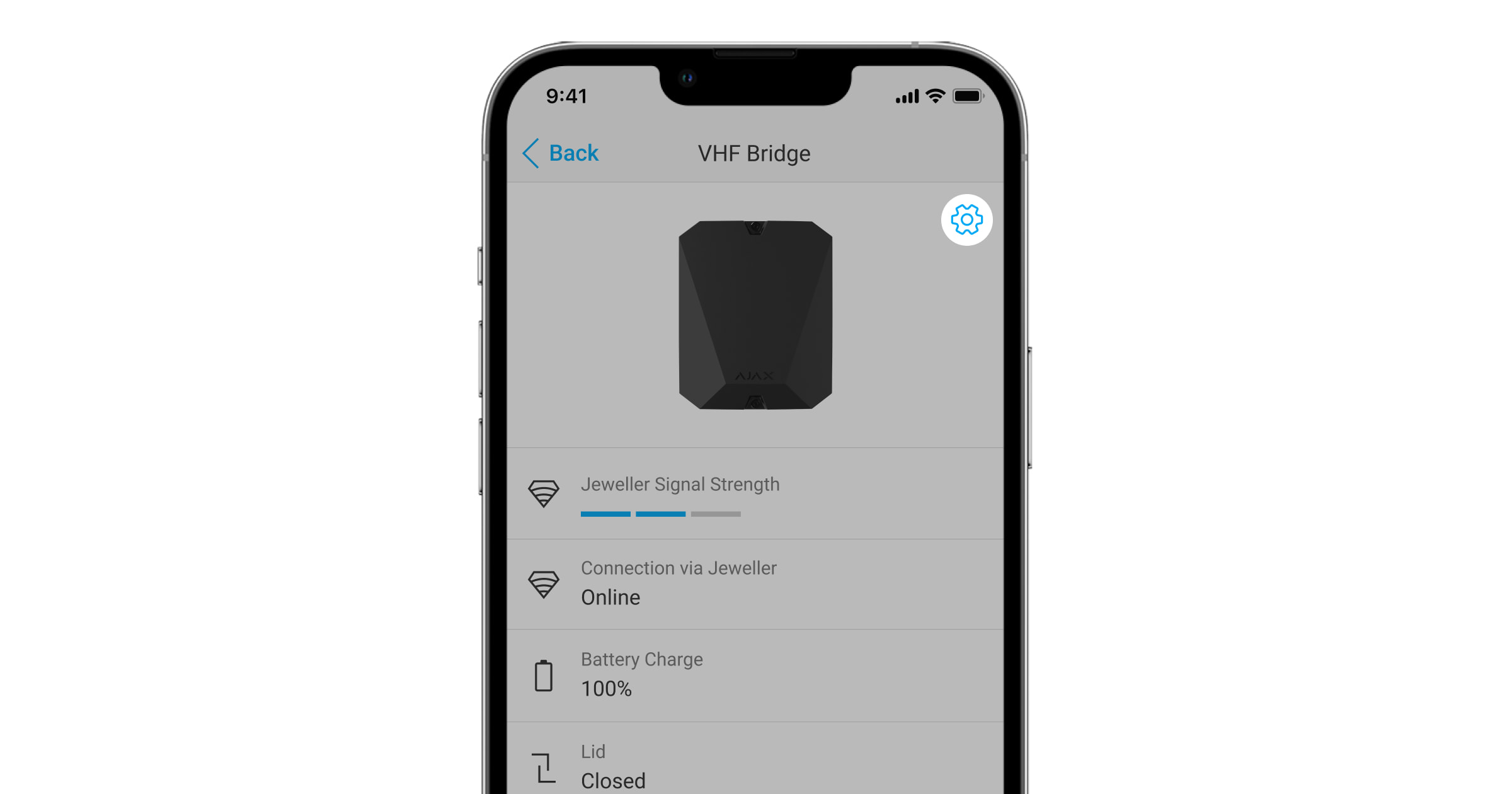
Icons
Icons display some of the vhfBridge Jeweller states. You can check them in the Ajax app in the Devices ![]() tab.
tab.
| Icon | Meaning |
|
Jeweller Signal Strength. Displays the signal strength between the hub and vhfBridge Jeweller. Recommended value is 2–3 bars. |
|
| The charge level of the battery connected to vhfBridge Jeweller. | |
| Is displayed when vhfBridge Jeweller is operating via a radio signal range extender. | |
|
vhfBridge Jeweller is disabled. |
|
|
vhfBridge Jeweller tamper triggering events are disabled. |
|
| The device has lost connection with the hub or the hub has lost connection with the Ajax Cloud server. | |
|
The device has not been transferred to the new hub. |
States
States can be found in the Ajax app:
- Go to the Devices tab.
- Select vhfBridge Jeweller from the list.
| Parameter | Meaning |
| Data import | Displays the error when transferring data to the new hub:
|
| Malfunction |
Click The field is displayed only if a battery charge malfunction is detected. |
| Jeweller Signal Strength |
Signal strength between the hub and vhfBridge Jeweller. Recommended value is 2–3 bars. |
| Connection via Jeweller | Connection status between the hub and vhfBridge Jeweller:
|
| Battery Charge |
Battery charge level of the device. Displayed as a percentage. How battery charge is displayed in Ajax apps Also, this field can display the battery status:
|
| Lid |
The status of tampers that respond to detachment or violation of the integrity of the casing. |
| External Power | The presence of the 100–240 V~ external power supply:
|
| Name of ReX range extender | Radio signal range extender connection status:
Please note that the field is displayed if vhfBridge Jeweller is operated via a radio signal range extender. |
| Permanent Deactivation | Shows the status of the device permanent deactivation function:
|
| Firmware | vhfBridge Jeweller firmware version. |
| Device ID | vhfBridge Jeweller ID/serial number. Also located on the device box, its board, and the casing. |
| Device No. | Device loop (zone) number. |
vhfBridge Jeweller settings
Settings can be changed in the Ajax app:
- Go to the Devices tab.
- Select vhfBridge Jeweller from the list.
- Go to Settings by clicking the icon
 in the upper right corner.
 - Set the parameters.
- Click Back to save the new settings.
Please note that after editing the settings, you should click the Back button to save them.
| Configuration | Meaning |
| Name |
vhfBridge Jeweller name. Displayed in the text of SMS and notifications in the event feed. To change the device name, click on the pencil icon. The name can contain up to 12 Cyrillic characters or up to 24 Latin characters. |
| Room |
Selecting the virtual room to which vhfBridge Jeweller is assigned. The room name is displayed in the text of SMS and notifications in the event feed. |
| Track battery charge time |
Set up the battery charge duration. When this option is enabled, the system will send a malfunction notification if the battery connected to vhfBridge Jeweller has been charging more than 40 hours. Disable tracking if the VHF transmitter is powered directly from the battery and not from the vhfBridge Jeweller power terminals. |
| Pulse Duration, sec |
Pulse time on an event (from 1 to 255 seconds). Set in increment of 1 second. The default value is 5 seconds. |
| Jeweller Signal Strength Test |
Switches vhfBridge Jeweller to the Jeweller signal strength test mode. The test allows you to check the signal strength between the hub and vhfBridge Jeweller and determine the optimal installation location. |
| Permanent Deactivation |
Allows the user to disable the device without removing it from the system. Three options are available:
|
| User Guide | Opens vhfBridge Jeweller User Guide in the Ajax app. |
| Unpair Device | Unpairs vhfBridge Jeweller, disconnects it from the hub, and deletes its settings. |
vhfBridge Jeweller output configuration
By default, vhfBridge Jeweller outputs are configured as follows:
- 1st output — intrusion
- 2nd output — panic button
- 3rd output — malfunction
- 4th output — tamper
- 5th output — loss of vhfBridge Jeweller power supply
- 6th output — power loss of the hub
- 7th output — hub battery discharged
- 8th output — loss of communication between the hub and vhfBridge Jeweller
The settings of outputs can be changed in the Ajax app:
- Go to the Devices tab.
- Find vhfBridge Jeweller in the list of devices.
- Go to the Outputs menu.
- Find the output in the list and go to its Settings by clicking the gear icon .
- Set the parameters.
- Click Back to save the new settings.
| Configuration | Meaning |
| Type of Event |
Selection of the event type to which vhfBridge Jeweller output reacts. Check the complete list of event types and their icons below. |
| Connection type | Selection of the output type:
|
| Operating mode | Selecting the output operating mode:
This setting is available for users with administrator rights or in the PRO app. If the device is connected to hubs with firmware version OS Malevich 2.27 and later. |
Event types of vhfBridge Jeweller outputs
| Icon | Type of event | Operating mode | Description |
 |
Not assigned | No | Output disabled. |
 |
Intrusion | Pulse | Alarm when motion, opening, and other detectors are triggered. |
 |
Fire | Pulse | Alarm when fire detectors are triggered. |
 |
Auxiliary alarm | Pulse | Alarm when pressing the auxiliary request alert button. |
 |
Panic button | Pulse | Alarm by clicking:
|
 |
Any alarm | Pulse | Alarm of any connected detector. |
 |
Malfunction | Pulse | Any malfunction of the connected detectors. |
 |
Transponder external power failure | Bistable | Loss of external 110–240 V~ power supply to vhfBridge Jeweller transponder. |
 |
Transponder battery low | Bistable | vhfBridge Jeweller backup battery is discharged. |
 |
Hub external power failure | Bistable | Loss of external 110–240 V~ power supply to the hub. |
 |
Hub battery low | Bistable | Hub backup battery is discharged. |
 |
Lid | Pulse | Triggering of tamper of any device in the system. |
 |
Security mode change | Bistable | Changing the security mode of an object or group. |
 |
Confirmed intrusion alarm | Pulse | Confirmed alarm according to PD 6662:2017. |
 |
Confirmed hold-up alarm | Pulse | Confirmed hold-up device alarm according to PD 6662:2017. |
 |
Hub-transponder connection loss | Bistable | Loss of vhfBridge Jeweller connection with the hub / radio signal range extender via Jeweller channel. |
The time before sending an event regarding the loss of communication between the hub and vhfBridge Jeweller to the CMS is calculated with the following formula:
“Hub — detector” polling interval × 30 undelivered packets.
With the minimum values of the “hub — detector” polling interval, an event regarding the loss of communication with the hub is sent to the CMS in 6 minutes.
Connecting VHF transmitter to vhfBridge Jeweller
List of recommended VHF transmitters
- Hawk VHF Alarm Transmitter (FSK Electronics)
- TX750C (RDC)
- TR-41 (Puper)
vhfBridge Jeweller can be connected to any VHF transmitter with relay inputs. Connection via UART, RS-485, and other interfaces is not supported.
How to connect a VHF transmitter to vhfBridge Jeweller
When connecting the VHF transmitter, do not twist the wires together, but solder them. The ends of the VHF transmitter wires, which will be inserted into the vhfBridge Jeweller terminals should be tinned or crimped with a special sleeve.
- Turn off the vhfBridge Jeweller power (if power was connected).
- Turn off vhfBridge Jeweller.
- Select vhfBridge Jeweller outputs to which you want to connect the VHF transmitter.
- Pull the VHF transmitter wires into the vhfBridge Jeweller casing through the holes.
There are perforated sections on the casing that can be broken off so that the cable could be pulled through them.
- Connect the VHF transmitter to the control outputs of vhfBridge Jeweller according to the wiring diagram in the User Guide supplied by the VHF transmitter manufacturer.
- Fasten the cable securely to the vhfBridge Jeweller terminals using a straight screwdriver (slot PL 3.0).
- Connect the power to the VHF transmitter.
If a VHF transmitter requires 12 V power to operate, it can be connected to the power terminals of the corresponding vhfBridge Jeweller zone. Do not connect the external power supply to the transmitter power terminals, as this may damage the device.
- Connect power to vhfBridge Jeweller.
- Turn on vhfBridge Jeweller.
vhfBridge Jeweller functionality testing
Integration module functionality tests do not start immediately but not later than over a single “hub — detector” polling interval (36 seconds with standard hub settings). You can change the polling period of devices in the Jeweller menu of the hub settings.
Tests are available in the device settings menu:
- Sign in to the Ajax app.
- Go to the Devices menu .
- Select vhfBridge Jeweller.
- Go to Settings by clicking on the gear icon .
Available tests:
Selecting vhfBridge Jeweller placement
The placement of vhfBridge Jeweller determines its distance from the hub and the presence of obstacles between them that impede the passage of the radio signal: walls, inter-floor constructions, or large-sized objects located in the room.
Be sure to check the signal strength at the installation site. If the signal strength is low (a single bar), we cannot guarantee a stable operation of the security system. At the very least, relocate the device as repositioning even by 20 cm can significantly improve signal reception.
If poor or unstable signal strength is still reported after the relocation of the device, use the radio signal range extender.
When choosing the installation location, consider the distance between vhfBridge Jeweller and the VHF transmitter: the cable length should be sufficient for connection.
The minimum distance between vhfBridge Jeweller and the radio transmitter is 2 meters and the maximum distance is 7 meters. The minimum distance is required to avoid signal overlapping. The maximum distance allowed will help avoid signal attenuation in the cable.
Material and cross-section of the cable for connecting a VHF transmitter are determined by the manufacturer’s requirements and the maximum current. All requirements can be found in the manual or from the customer service of the VHF transmitter manufacturer.
vhfBridge Jeweller installation
Prior to mounting vhfBridge Jeweller, ensure that you have selected the optimal location corresponding to these instructions.
The transponder casing should be mounted on a vertical surface. If installed on a horizontal surface, the tamper will not work when somebody attempts to dismantle the transponder.
To install vhfBridge Jeweller:
- Remove the vhfBridge Jeweller casing lid by unscrewing the bottom and top screws with the bundled hex wrench.

- Remove the vhfBridge Jeweller board from the holders by pulling them to the sides.

- Prepare cable openings in advance by carefully breaking out the perforated parts of the casing.

- Fasten the casing to a vertical surface at the chosen installation location using the bundled screws. When attaching, use all the fixation points on the casing. One of them, in the perforated part of the mount above the tamper, is needed to trigger the tamper on the back of the board in case of an attempt to tear the casing off the surface.

- Run the cables into the transponder casing through the previously made holes.
- Install the vhfBridge Jeweller board into the casing on the racks.

- Connect VHF transmitter to vhfBridge Jeweller. Follow the polarity and connection order of the wires. Securely fasten the conductors to the terminals.
- Secure the cable with cable ties using special mounts inside the casing.

- Install a 12 V⎓ backup battery on the special holders in the casing. Please note that vhfBridge Jeweller cannot be connected to third-party power supply units.
We recommend using a 12 V⎓ battery of 4 or 7 Ah. For such batteries, special holders in the casing are designed. You can also use similar batteries of a different capacity, of the matching size, and with a charging time of no more than 30 hours. The maximum dimensions of the battery to be installed in the casing are 150 × 65 × 94 mm, and the weight is 5 kg.
- Connect a backup battery to the board terminals according to the wiring diagram below (use the bundled cable). Follow the polarity and connection order of the wires. Securely fasten the conductors to the terminals.
- Connect 100–240 V~ external power supply.
- Add an integration module to the system.
- Install the lid on the casing and fix it with the bundled screws.
- Test vhfBridge Jeweller and connected VHF transmitter.
Do not install vhfBridge Jeweller
- Outdoors. Doing so may cause the device to malfunction or not work properly.
- Near metal objects or mirrors (for example, in a metal cabinet). They can shield and attenuate the radio signal.
- Inside premises with temperature and humidity outside the permissible limits. Doing so may cause the device to malfunction or not work properly.
- At a distance less than 1 meter from the hub or range extender. This could result in the loss of connection with the hub.
- At a distance less than 2 meters from the VHF transmitter. The minimum distance is required to avoid signal overlapping
- At a distance more than 7 meters from the VHF transmitter. The maximum distance allowed will help avoid signal attenuation in the cable.
Maintenance
Check the functionality of vhfBridge Jeweller regularly. The optimal frequency of checks is once every three months. Clean the casing from dust, cobwebs, and other contaminants as they emerge. Use a soft dry cloth suitable for equipment care. Do not use any substances containing alcohol, acetone, gasoline, and other active solvents to clean the device.
Technical Specifications
Warranty
Warranty for the Limited Liability Company “Ajax Systems Manufacturing” products is valid for 2 years after the purchase.
If the device does not work correctly, you should first contact the support service. In most cases, technical issues can be resolved remotely.
Contact Technical Support:
