Superior Transmitter Fibra is an integration module for connecting a third-party wired device into an Ajax system. It can be used to connect roller shutters, panic or auxiliary buttons, indoor or outdoor motion detectors, as well as opening, vibration, glass break, fire, gas, leak detectors, or other wired devices.
The integration module supports NC, NO, EOL, 2EOL, 3EOL, or Roller Shutter device connection types and can supply the connected device with 10.5–15 V⎓, up to 50 mA of power.
The module operates in the Ajax system and exchanges data with the hub using the secure Fibra wired communication protocol.
The integration module is compatible with Superior Hub Hybrid (2G) and Superior Hub Hybrid (4G). Connection to other hubs, radio signal range extenders, ocBridge Plus, and uartBridge is not provided.
Superior Transmitter Fibra is part of the Fibra product line of wired devices. Only accredited Ajax Systems partners can install, sell, and administer these devices.
Functional elements
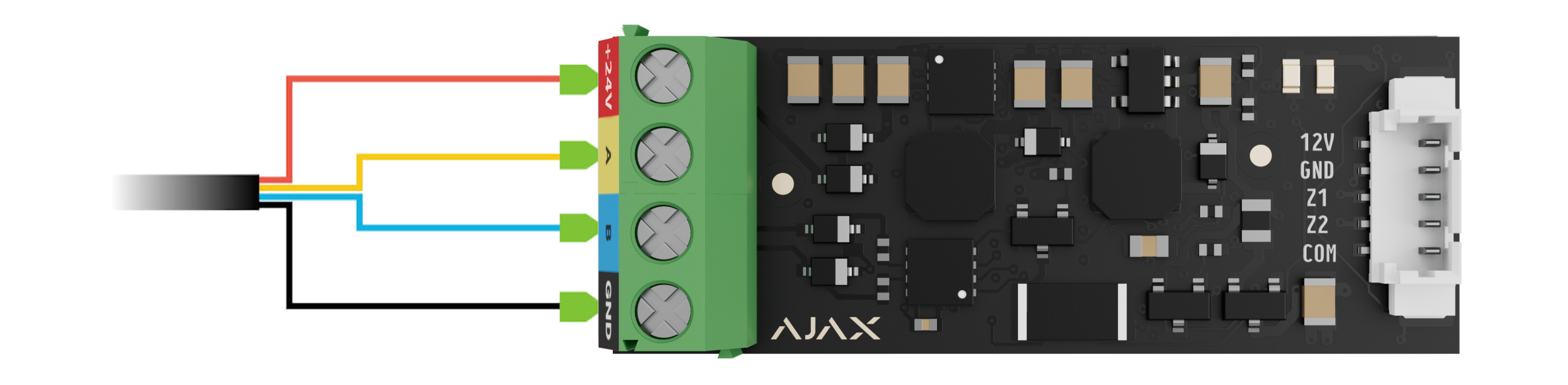
- Input terminals for connecting the Fibra line to Superior Transmitter Fibra.
- QR code with the device ID for adding the module to the Ajax system.
- LED indicators of the module.
- Connector for a wired device.
- Accessory 5-pin cable.
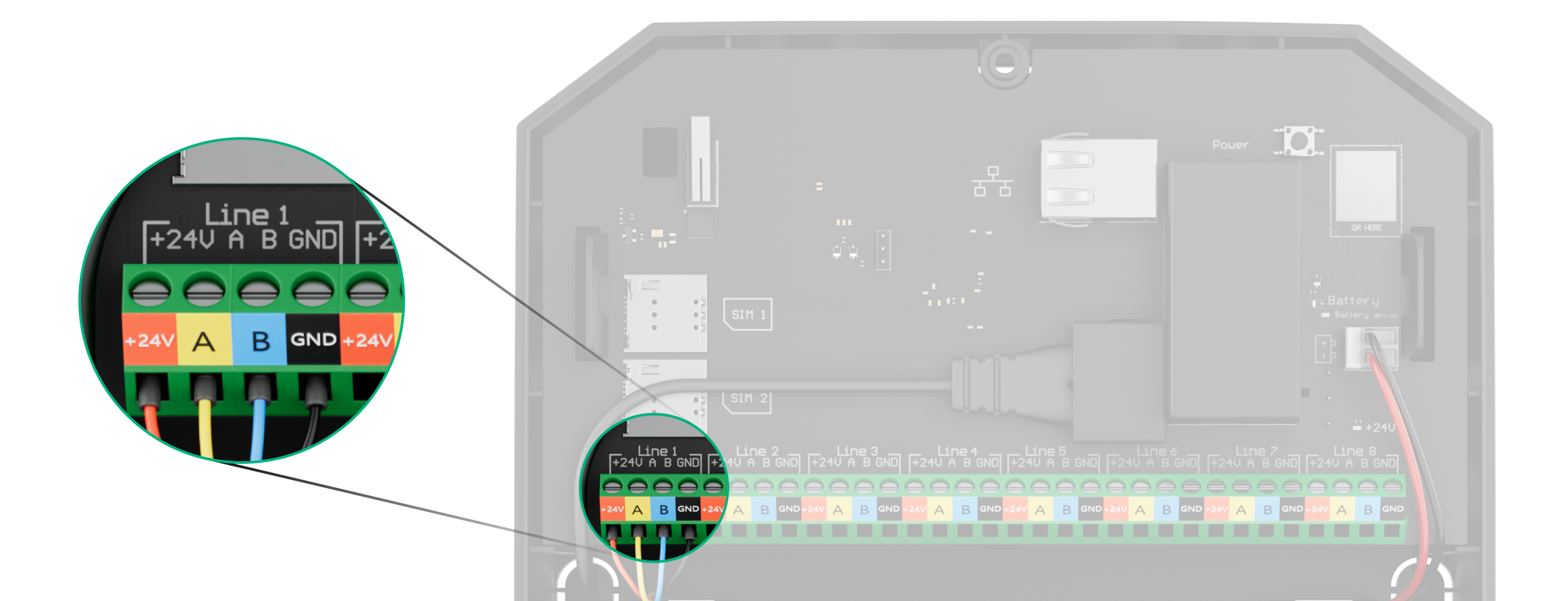
Terminals for connecting Superior Transmitter Fibra to the hub:
- +24V — 24 V⎓ power supply terminal.
- А, B — signal terminals.
- GND — power ground terminal.
Connector pins for connecting a wired device:
- 12V — 10.5–15 V⎓, up to 50 mA power supply output for a wired device.
- GND — ground.
- Z1–Z2 — inputs for connecting a wired device.
- COM — common input for connecting signal contacts of a wired device.
Superior Transmitter Fibra has 2 inputs (Z1 and Z2) to connect a wired device using the AATT (i.e., Alarm Alarm Tamper Tamper) scheme.
Operating principle
Superior Transmitter Fibra is designed to integrate a third-party wired device into an Ajax system. The integration module receives information about alarms, malfunctions, and events from the device through a wired connection. After that, it sends the event to Superior Hub Hybrid using the Fibra wired communication protocol. Then, Superior Hub Hybrid sends notifications to users and the security company CMS (central monitoring station).
The wired device connected to Superior Transmitter Fibra can operate in one of the following sensor modes:
- Detect alarms
- Switch arming modes
- Control of blocking element
- Control of bolt lock
Superior Transmitter Fibra is used to integrate panic or auxiliary buttons, indoor or outdoor motion detectors, as well as opening, vibration, glass break, fire, gas, or water leak detectors, etc.
Also, you can set up KeyArm Zone that allows switching system arming modes with a third-party device connected to Superior Transmitter Fibra. KeyArm allows you to arm/disarm the system, individual groups, or manage Night Mode.
The device type is specified in the settings of the zone to which the wired device is connected. The selected type determines the text of alarm notifications and events of the connected device, as well as event codes transmitted to the CMS.
Sensor modes Control of blocking element and Control of bolt lock is used to integrate third party blocking elements and bolt switch contacts to the Ajax system according to the unavoidability principle (German: Zwangsläufigkeit).
Types of wired devices
| Detect alarms operating mode | |||
| Event type | Icon | Meaning | |
| Tamper alarm |
 |
Event of a device tamper triggering. | |
| Intrusion |
 |
Alarm when motion, opening, and other detectors are triggered. | |
| Fire |
 |
Alarm when fire detectors are triggered. | |
| Auxiliary alarm |
 |
Alarm when the auxiliary button is pressed. | |
| Panic button |
 |
Alarm when the panic button is pressed. | |
| Gas alarm |
 |
Alarm when gas concentration is exceeded. | |
| Malfunction |
 |
An event caused by a malfunction of a connected detector or device. | |
| Leakage |
 |
Alarm caused by flooding. | |
| Glass break |
 |
Alarm when the glass break sensor is triggered. This event type operates only in Pulse operating mode. |
|
| High temperature |
 |
Alarm when the upper temperature limit is exceeded. | |
| Low temperature |
 |
Alarm when the lower temperature limit is exceeded. | |
| Masking |
 |
Alarm when the device masking is detected. | |
| Duress code (opening) |
 |
Alarm when the duress code is entered. This event type operates only in Pulse operating mode. |
|
| Vibration (seismic sensor) |
 |
Alarm when the seismic sensor is triggered. This event type operates only in Pulse operating mode. |
|
| Custom |
 |
The event type is customized by the user. Not sent to the security company monitoring station and users via SMS. |
|
| Switch arming modes | |||
| Icon | Meaning | ||
 |
You can set up KeyArm Zone that allows switching system arming modes with a third-party device connected to Superior MultiTransmitter Fibra. KeyArm allows you to arm/disarm the system, individual groups, or manage Night Mode.
The KeyArm feature is supported by compatible hubs with OS Malevich 2.17 and later. If the Followed group feature is configured for groups, their security state can automatically change depending on their settings and initiators’ states. . |
||
| Control of blocking element | |||
| Icon | Meaning | ||
 |
You can set up Control of blocking element that allows receiving notification on the status of third-party blocking element. The Control of blocking element feature is supported by compatible hubs with OS Malevich 2.25 and later. This feature is part of the unavoidability principle (German: Zwangsläufigkeit) flow. |
||
| Control of bolt lock | |||
| Icon | Meaning | ||
 |
You can set up Control of bolt lock that allows receiving notifications about the status of the lock bolt. The Control of bolt lock feature is supported by compatible hubs with OS Malevich 2.25 and later. This feature is part of the unavoidability principle (German: Zwangsläufigkeit) flow. |
||
Wired devices connection types
- Without EOL.
- EOL (connection with one resistor).
- 2EOL (connection with two resistors).
- 3EOL (connection with three resistors).
- Roller Shutter.
In the Ajax app, you can select the normal state (normally open or normally closed) for the terminal pairs: alarm, tamper, and malfunction. This allows connecting any potential-free “dry” contact detector of any configuration to Superior Transmitter Fibra.
Fibra data transfer protocol
The integration module uses Fibra technology to transmit alarms and events. It is a wired data transfer protocol for fast and reliable two-way communication between the hub and integration module. Using the bus connection method, Fibra delivers alarms and events instantly, even if 100 devices are connected to the system.
Fibra supports block encryption featuring a dynamic key and verifies each communication session with devices to prevent sabotage and spoofing. The protocol provides for regular polling of devices by the hub at a specified frequency to control communication and display the state of system devices in Ajax apps.
Sending events to the monitoring station
The Ajax system can transmit alarms to both PRO Desktop monitoring app and the central monitoring station (CMS) in the formats of SurGard (Contact ID), SIA DC-09 (ADM-CID), ADEMCO 685, and other protocols.
Superior Transmitter Fibra can transmit the following events:
- Alarm/restoration of the connected device.
- Loss/recovery of communication between Superior Transmitter Fibra, connected devices, and the hub.
- Permanent deactivation/activation of Superior Transmitter Fibra and connected devices.
- One-time deactivation/activation of Superior Transmitter Fibra and connected devices.
- Short circuit on the line/power supply restoration of connected devices.
- Short circuit of or damage to the line connecting third-party devices to Superior Transmitter Fibra (for EOL connections).
When an alarm is received, the operator at the security company’s monitoring station knows what happened and precisely where to dispatch a rapid response team. The addressability of Ajax devices allows sending events to PRO Desktop or the CMS, including the device type, its name, security group, and virtual room. Please note that the list of transmitted parameters might vary depending on the CMS type and the selected communication protocol for the monitoring station.
The device’s ID and number can be found in its states in the Ajax app.
Adding to the system
Superior Transmitter Fibra is compatible only with Superior Hub Hybrid (2G) and Superior Hub Hybrid (4G). Only verified partners can add and configure Fibra devices in Ajax PRO apps.
Before adding a device
- Install an Ajax PRO app.
- Log in to a PRO account or create a new one.
- Select a space or create a new one.

The space functionality is available for apps of such versions or later:
- Ajax Security System 3.0 for iOS;
- Ajax Security System 3.0 for Android;
- Ajax PRO: Tool for Engineers 2.0 for iOS;
- Ajax PRO: Tool for Engineers 2.0 for Android;
- Ajax PRO Desktop 4.0 for macOS;
- Ajax PRO Desktop 4.0 for Windows.
- Add at least one virtual room.
- Add a compatible hub to the space. Ensure the hub is switched on and has internet access via Ethernet, Wi-Fi, and/or mobile network.
- Ensure the space is disarmed, and the hub is not starting an update by checking statuses in the Ajax app.
Connecting to the hub
There are two ways to add devices in the Ajax PRO app: automatically and manually.
- Open the Ajax PRO app and select the hub to which you want to add Superior Transmitter Fibra.
- Go to the Devices
 tab and click Add device.
 - Select Add all Fibra devices. The hub will scan the Fibra lines. After scanning, all devices connected to the hub that have not been added to the system will be displayed.
- Select the desired device from the list. Upon selection, the LED indicator will flash to identify this device.
- Name the device, and select the room and security group if Group Mode is enabled. Click Save.
Once connected to the hub, the module will appear in the list of hub devices in the Ajax app. The device status update frequency in the list depends on the Jeweller/Fibra settings, with the default value of 36 seconds.
Superior Transmitter Fibra works with only one hub. When connected to a new hub, the device stops sending events to the old one.
Adding the module to a new hub does not automatically remove it from the device list of the old hub. This must be done through the Ajax app.
Adding a connected wired device
In the Ajax system, each device connected to Superior Transmitter Fibra occupies one slot within the hub’s device limit.
- In the Ajax PRO app, go to the Devices tab.
- Find Superior Transmitter Fibra in the device list.
- Click on the Devices menu under the integration module icon.
- Click Add Device.
- Assign a name to the device.
- Select the wired zone to which the device will be physically connected.
- Select a virtual room and a security group if the Group Mode is enabled.
- Press Add Device. The device will be added within 30 seconds.
The device status update depends on the Jeweller/Fibra settings; the default value is 36 seconds.
If the connection attempt fails, verify that the wired connection is correctly set up before trying again. If the maximum number of devices (100 for Superior Hub Hybrid) has already been added to the hub, you will receive an error notification while adding.
Malfunctions
When a Superior Transmitter Fibra malfunction is detected, the Ajax app displays a malfunction counter on the device icon. All malfunctions are indicated in the module states. Fields with malfunctions will be highlighted in red.
A malfunction is displayed if connection with a hub is lost.
A malfunction of the connected device is displayed if:
- The device enclosure is open (tamper triggering).
- There is no connection between the integration module and the device (contacts damaged).
- Incorrect connection of resistors (resistor resistance error).
- Short circuit on the power supply line for the device.
Fire alarms reset
In case of an alarm of a fire detector connected to Superior Transmitter Fibra, the Ajax app displays the notification prompting to reset the alarm. The reset returns the fire detector to its normal state so it can continue detecting a fire.
If you do not reset the fire alarm, the detector will not respond to the next fire, as it will remain in alarm mode.
There are two ways to reset fire alarms:
- Tap Reset in the fire alarm notification in the app.
- Go to the Devices tab and find Superior Transmitter Fibra in the list. Tap
 , then tap Reset to confirm the fire alarm reset.
Icons
The icons in the app display some module states. To access them:
- Sign in to the Ajax app.
- Select a hub.
- Go to the Devices tab.
Superior Transmitter Fibra icons
| Icon | Meaning |
|
Fibra signal strength — displays the signal strength between the hub and the integration module. Recommended value is 2–3 bars. |
|
| A fire detector connected to Superior Transmitter Fibra has registered an alarm. | |
| Superior Transmitter Fibra has a malfunction. A list of malfunctions is available in the States of the integration module. | |
|
Superior Transmitter Fibra is disabled. |
|
|
Superior Transmitter Fibra is disabled until the first event of disarming the system. |
|
| The device has lost connection with the hub or the hub has lost connection with the Ajax Cloud server. | |
|
The device has not been transferred to the new hub. |
Icons of connected devices
| Icon | Meaning |
| Chime function is enabled. | |
|
|
Delay When Entering and/or Leaving is enabled. |
| The device operates in the Always active mode. | |
| The device will work when Night Mode is enabled. | |
|
The device state is OK. Displayed for EOL, NC, NO, and Roller Shutter connections only. |
|
|
The device is short-circuited. Displayed for EOL, NC, NO, and Roller Shutter connections only. |
|
| The device tamper state is OK.* | |
| Device tamper alarm.* | |
| The state of the intrusion sensors is OK.* | |
| Intrusion alarm.* | |
| The state of the auxiliary request button is OK.* | |
| Alarm when the auxiliary button is pressed.* | |
| The state of the panic button is OK.* | |
| Alarm when the panic button is pressed.* | |
| The state of the fire sensor is OK.* | |
| The device has detected a fire alarm.* | |
| The state of the gas sensor is OK.* | |
| Alarm when the gas concentration is exceeded.* | |
| The device state is OK.* | |
| Device malfunction is detected.* | |
| The state of the flooding sensor is OK.* | |
| Alarm caused by the flooding.* | |
| The state of the glass break sensor is OK.* | |
| Glass break alarm.* | |
| The state of the high temperature sensor is OK.* | |
| Alarm when the upper temperature limit is exceeded.* | |
| The state of the low temperature sensor is OK.* | |
| Alarm when the lower temperature limit is exceeded.* | |
| The state of the masking sensor is OK.* | |
| Masking alarm.* | |
| The state of the duress code device is OK.* | |
| Alarm caused by the system disarming using the duress code device.* | |
| The state of the vibration (seismic) sensor is OK.* | |
| Vibration (seismic) alarm.* | |
| The state of the device for which the custom type of event is selected is OK.* | |
| The alarm of the device for which the custom type of event is selected.* | |
| The sensor operates in the Switch arming modes mode. | |
| The state of the Blocking element. | |
| The state of the Bolt lock. | |
| The device is automatically disabled due to exceeding the number of alarms. | |
| The device is automatically disabled by the restoration timer. | |
| The device is disabled by the system user. | |
| The device is disabled until the first event of disarming the system. |
* Icon is displayed for 2EOL and 3EOL connections only.
States
Superior Transmitter Fibra states
The states include information about the integration module and its operating parameters. You can find the states of Superior Transmitter Fibra in the Ajax apps:
- Go to the Devices tab.
- Select Superior Transmitter Fibra from the list.
| Parameter | Meaning |
| Data import | Displays the error when transferring data to the new hub:
|
| Malfunction |
Clicking the The field is displayed only if a malfunction is detected. |
| Fibra signal strength |
Fibra signal strength between Superior Transmitter Fibra and the hub. The recommended value is 2–3 bars. Fibra is the protocol for transmitting Superior Transmitter Fibra events and alarms. |
| Connection via Fibra | Connection status on the Fibra line between Superior Transmitter Fibra and the hub:
|
| Line voltage | The voltage value on the Fibra line to which the integration module is connected. |
| Power Supply for Connected Detectors | The status of the power supply for connected detectors 10.5–15 V⎓, up to 50 mA:
|
| Permanent Deactivation | The status of the device permanent deactivation setting:
|
| One-Time Deactivation | The status of the device one-time deactivation setting:
|
| Firmware | Device firmware version. |
| Device ID | Superior Transmitter Fibra ID. Also available on the board of the integration module, the back of the casing, and its packaging. |
| Device No. | Number of the device loop (zone). |
| Line No. | The number of the Fibra line to which Superior Transmitter Fibra is connected. |
States of connected devices
The states display information about the device and its operating parameters. You can find the states of the device connected to Superior Transmitter Fibra in the Ajax apps:
- Go to the Devices tab.
- Find Superior Transmitter Fibra in the list.
- Click on Devices under the Superior Transmitter Fibra icon.
- Select the device from the list.
| Parameter | Meaning |
| Malfunction |
Clicking the The field is displayed only if a malfunction is detected. |
| Name of the connected wired device | Connection status on the line between Superior Transmitter Fibra and the connected wired device:
|
|
Device state Displayed for Without EOL, EOL, and Roller Shutter connection types |
The status of the connected wired device:
|
|
Tamper sensor Displayed for 2EOL and 3EOL connection types |
Tamper status of the connected wired device:
|
|
“Name of the selected event type” sensor Displayed for 2EOL and 3EOL connection types |
The status of the connected wired device:
|
| Always Active |
If the option is enabled, the device connected to Superior Transmitter Fibra is constantly armed and reports alarms. You can configure the option only for certain event types. |
|
Device resistance Displayed for EOL, 2EOL, and 3EOL connection types |
The total resistance of the resistor(s) connected to the device is measured automatically. Values can also be set manually in 100-ohm increments. |
| Permanent Deactivation |
Allows the user to disable the device without removing it from the system. Two options are available:
You can also separately configure the device disconnection:
The feature is configured in the Ajax PRO apps. |
| One-Time Deactivation | The status of the device one-time deactivation setting:
|
| Alarm Reaction | |
| Operating Mode | Shows how the detector reacts to alarms:
|
| Delay When Entering, s |
Delay time when entering: 5 to 120 seconds. Delay when entering (alarm activation delay) is the time the user has to disarm the security system after entering the secured area. |
| Delay When Leaving, s |
Delay time when leaving: 5 to 120 seconds. Delay when leaving (arming delay) is the time the user has to leave the secured area after arming. |
| Arm in Night Mode | When this option is enabled, the device will enter the armed mode when the system is set to Night Mode. |
| Night Mode Delay When Entering, s |
Delay time when entering in Night Mode: 5 to 120 seconds. Delay when entering (alarm activation delay) is the time the user has to disarm the security system after entering the secured area. |
| Night Mode Delay When Leaving, s |
Delay when leaving in Night Mode: 5 to 120 seconds. Delay when leaving (arming delay) is the time the user has to leave the secured area after arming. |
| Wired input | Superior Transmitter Fibra zone number to which a wired device is connected. |
| Device No. | Device loop (zone) number. |
Settings
Superior Transmitter Fibra settings
To change the Superior Transmitter Fibra settings in the Ajax app:
- Go to the Devices tab.
- Select Superior Transmitter Fibra from the list.
- Go to Settings by clicking on the
 icon.
icon. - Set the required settings.
- Click Back to save the new settings.
| Settings | Meaning |
| Name |
Name of the module. Displayed in the list of hub devices, SMS text, and notifications in the event feed. To change the name of the device, click on the text field. The name can contain up to 12 Cyrillic characters or up to 24 Latin characters. |
| Room |
Selecting the virtual room to which Superior Transmitter Fibra is assigned. The room name is displayed in the text of SMS and notifications in the event feed. |
| Power Supply for Connected Detectors |
Enable power supply 10.5–15 V⎓, up to 50 mA for the connected detector. The option is disabled by default. |
| Connected Detectors Current Consumption |
Set the current consumption when the power supply for the connected detector is enabled. Adjust the current value from 10 to 50 mA. Set the maximum consumption for devices that require power supply from the integration module. This value helps to determine if all devices have enough power supply from the line in current system configuration. |
| Alert with a siren if power supply for detectors is shorted out |
When this option is enabled, the sirens added to the system will activate in case of a short circuit of the power supply for detectors. The option is enabled by default. |
| Fibra Signal Strength Test |
Switches the device to the Fibra signal strength testing mode. |
| User Guide | Opens Superior Transmitter Fibra user guide in the Ajax app. |
| Permanent Deactivation |
Allows the user to deactivate the device without removing it from the system. Two options are available:
|
| One-Time Deactivation |
Allows the user to disable events of the device until the first disarm. Two options are available:
|
| Delete Device | Unpairs the device, disconnects it from the hub, and deletes its settings. |
Settings of connected devices
To change the connected device settings, in the Ajax app:
- Go to the Devices tab.
- Find Superior Transmitter Fibra in the list.
- Click on Devices under the Superior Transmitter Fibra icon.
- Select the device from the list.
- Go to Settings by clicking on the icon.
- Set the parameters.
- Click Back to save the new settings.
| Setting | Meaning |
| Name |
Wired device name. Displayed in the list of hub devices, SMS text, and notifications in the event feed. To change the name, click on the text field. The name can contain up to 12 Cyrillic characters or up to 24 Latin characters. |
| Room |
Selecting the device’s virtual room. The room name is displayed in the text of SMS and notifications in the event feed. |
| Input type | Selecting the connection type of a third-party device:
|
| Default State | Selecting the normal contact state of the connected device:
|
| Sensor Mode | Selecting the sensor mode of the connected device:
|
| Arm Switch Settings | Configuring the arm switch if the Switch Arming Modes option is selected for the Sensor Mode setting:
|
| Type of Event |
Selecting an event type for the connected device. Refer to the Event types of wired devices section for more information. The text of notifications in the event feed and SMS, as well as the code transmitted to the security company monitoring station depends on the selected event type. This setting is available if Detect alarms option is selected for the Sensor mode setting. |
| Operating Mode | The operating mode of the connected device:
Be sure to set a type that matches the connected device. The pulsed detector in the bistable mode generates unnecessary restoration events. A bistable detector in pulsed mode, on the contrary, will not send restoration events. |
| Notify of changes in bolt lock state |
If the option is enabled, the system will notify the user each time the bolt lock change it’s state. This option is available if the Control of bolt lock option is selected for the Sensor mode setting. |
| Always Active |
If the option is enabled, the device connected to Superior Transmitter Fibra is constantly armed and reports alarms. You can configure the option only for certain event types. This setting is not available if Switch arming modes option is selected for the Sensor mode setting. |
| Pulse time | Pulse time of a device for detecting an alarm:
An alarm will be activated if the pulse from the device lasts longer than specified in this setting. This can be used to filter false triggerings. |
| Alert with a siren if alarm detected |
If the option is enabled, the sirens connected to the system are activated when an alarm is detected. This setting is available if Detect alarms option is selected for the Sensor mode setting. |
| Chime Settings |
Opens the Chime settings. The function works only for bistable devices. Notifications will not work for sensors in pulse mode or Always active mode. |
| Alarm Reaction | |
| Operating Mode | Specify how this device will react to alarms:
|
| Delay When Entering, s |
Delay time when entering: 5 to 120 seconds. Delay when entering (alarm activation delay) is the time the user has to disarm the security system after entering the secured area. |
| Delay When Leaving, s |
Delay time when leaving: 5 to 120 seconds. Delay when leaving (arming delay) is the time the user has to leave the secured area after arming the system. |
| Arm in Night Mode |
If the option is enabled, the device connected to the integration module will switch to armed mode when the system is set to Night Mode. |
| Night Mode Delay When Entering, s |
Delay time when entering in Night Mode: 5 to 120 seconds. Delay when entering (alarm activation delay) is the time the user has to disarm the security system after entering the secured area. |
| Night Mode Delay When Leaving, s |
Delay when leaving in Night Mode: 5 to 120 seconds. Delay when leaving (arming delay) is the time the user has to leave the secured area after arming. |
| Permanent Deactivation |
Allows the user to disable the device without removing it from the system. Two options are available:
You can also separately configure disconnecting of the device:
The feature is configured in the Ajax PRO apps. |
| One-Time Deactivation |
Allows the user to disable events of the device until the first event of disarming the system. Two options are available:
|
Indication
The Superior Transmitter Fibra LED indicator may light up green or red, depending on the status of the device.
| Event | Indication | Note |
| To be added to the hub, the device is selected from the list of devices found by scanning Fibra lines | Flashes green rapidly. | |
| The wired device connected to Superior Transmitter Fibra is triggered | Lights up green for about 0.6 seconds. | Depends on the Sensor mode setting configured for the wired device and the system security state. |
| Superior Transmitter Fibra is deleted from the hub | Lights up green for 0.3 s and goes out for 0.3 s six times. | |
| The connection of a wired device to Superior Transmitter Fibra is short-circuit or broken | Lights up red four times per 1 s. |
Functionality testing
The Ajax system offers several types of tests to help select the correct installation place for the devices. The tests do not start immediately; however, the waiting time does not exceed the duration of one “hub—device” polling interval. You can check and configure the polling interval in the hub settings (Hub → Settings ![]() → Jeweller/Fibra).
→ Jeweller/Fibra).
To run a test, in the Ajax app:
- Select the required hub.
- Go to the Devices tab.
- Select Superior Transmitter Fibra from the list.
- Go to the Settings .
- Run the Fibra Signal Strength Test.
Device placement
Follow these recommendations when designing the system project for an object. Only professionals should design and install the Ajax system. The list of authorized Ajax partners is available here.
Installing into a wired device
Superior Transmitter Fibra should be installed inside the wired detector casing. The module requires a space with the following minimum dimensions: 40 × 15 × 12.2 mm. Installation inside the wired detector casing protects Superior Transmitter Fibra from external impacts and secures it with a tamper alarm.
How not to install Superior Transmitter Fibra
- In places where temperature and humidity levels exceed the permissible limits, as this can damage the module.
- In places with low or unstable Fibra signal strength, as this might cause a loss of connection with the hub.
Fibra signal strength
The Fibra signal strength is determined by the number of undelivered or corrupted data packages over a certain period of time. The icon ![]() on the Devices
on the Devices ![]() tab indicates the signal strength:
tab indicates the signal strength:
- Three bars — excellent signal strength.
- Two bars — good signal strength.
- One bar — low signal strength, stable operation is not guaranteed.
- Crossed out icon — no signal.
Lines Power Supply Test
The test simulates the maximum energy consumption of devices connected to the hub. If the system passes the test successfully, all its devices have enough power supply in any situation.
If the connected third-party device requires power supply from Superior Transmitter Fibra, make sure you set the correct Connected Detectors Current Consumption value in the Superior Transmitter Fibra settings. It is required for the accurate Lines Power Supply Test results.
After the test, the app displays a notification with the status of each line:
- Test passed.
- Test passed with malfunctions.
- Test failed.
Designing
It is crucial to design the system project properly to ensure the correct installation and configuration of the devices. The design must consider the number and types of devices at the object, their exact locations and installation heights, the length of wired Fibra lines, the type of cable used, and other parameters. Refer to the article to learn tips for designing the Fibra system project.
Cable length and type
For Superior Transmitter Fibra
The maximum range of a wired connection using the Beam (Radial wiring) topology is 2,000 meters, and using the Ring topology — 500 meters.
Recommended cable types:
- U/UTP cat.5 4×2×0.51 mm (24 AWG) cable, copper conductor;
- 4×0.22 mm² signal cable, copper conductor.
Please note, the wired connection range might vary if other cable types are used. As of now, no other cable types have been tested.
For wired devices of third-party manufacturers
The maximum cable length for connecting third-party devices to Superior Transmitter Fibra is 3 meters.
- Recommended cable type — 4×0.22 mm² signal cable, copper conductor.
To connect a wired device to Superior Transmitter Fibra, we recommend using the accessory 5-pin cable. It has the required connector and is designed to place the integration module inside the wired detector casing.
Verification using a calculator
To ensure that the project is designed correctly and the system functions as intended in practice, we have developed a Fibra power supply calculator. It helps to check the communication quality and cable length for wired Fibra devices when designing the system project.
Additional information
Ajax Superior Transmitter Fibra supports EOL resistors with resistance from 1 to 15 kOhm. The total resistance of all resistors is up to 30 kOhm. To increase anti-sabotage protection, use EOL resistors with different resistances in one detector. The recommended resistance ratio of EOL resistors: R1=R, R2=2·R, R3=3·R.
Preparing for installation
Cable arrangement
Before laying cables, check the electrical and fire safety regulations applicable in your region. Strictly follow these standards and regulations. Tips for cable arrangement are available in this article.
Cable routing
Before beginning the installation, we strongly advise reviewing the Device placement section thoroughly. Stick to the outlined system project without deviation. Violation of the basic Superior Transmitter Fibra installation rules and the recommendations of this manual may lead to incorrect operation, as well as loss of connection with the device. Tips for cable routing are available in this article.
Preparing cables for connection
First, remove the insulation layer and strip the cable with a special insulation stripper. The ends of the wires inserted into the device terminals must be tinned or crimped with a sleeve. It ensures a reliable connection and protects the conductor from oxidation. Tips for preparing the cables are available in this article.
Installation
- Turn off the power of lines in the Ajax PRO app:
- Hub → Settings → Lines → Lines Power Supply.
- Hub → Settings
- Route the cable to connect Superior Transmitter Fibra to the hub casing. Connect the wires to the required hub line.
+24V — 24 V⎓ power terminal.
А, B — signal terminals.
GND — ground. - Prepare cable holes in the wired detector casing, inside which Superior Transmitter Fibra will be installed.
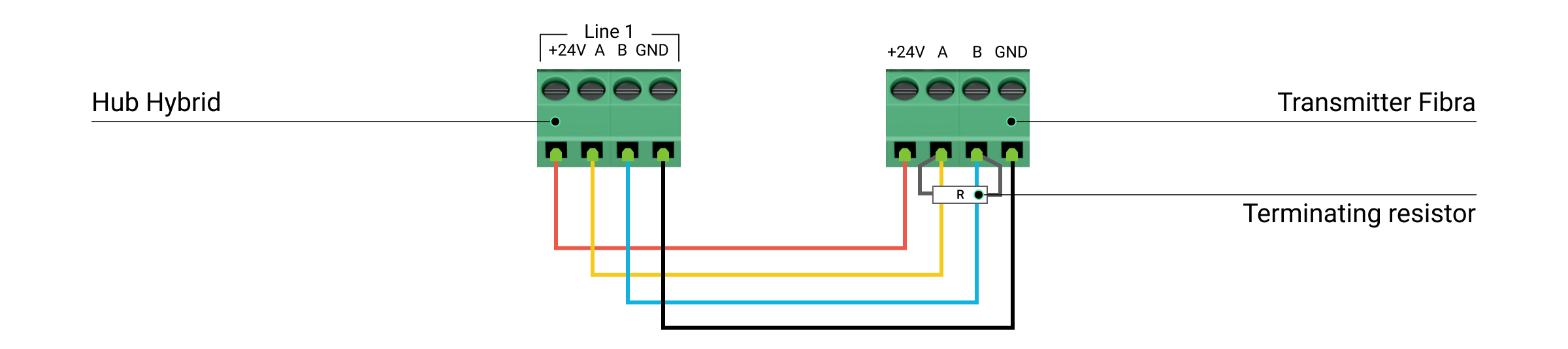
- Connect the wires to the Superior Transmitter Fibra input terminals according to the diagram below. Ensure the correct polarity and order of the wire connections. Firmly secure the cable to the terminals.
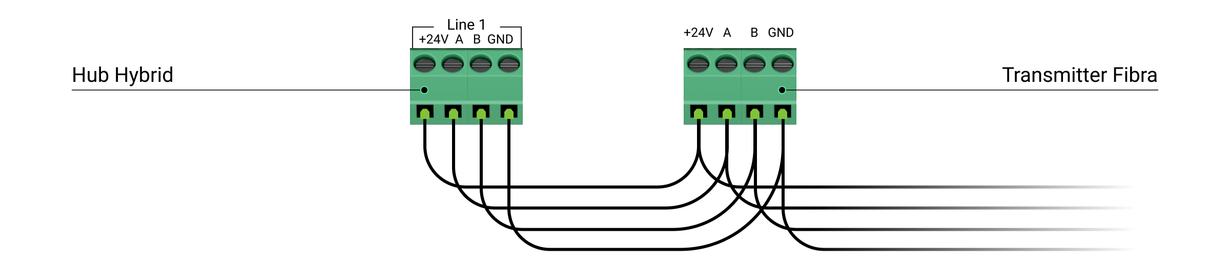
- If Superior Transmitter Fibra is not the last device on the Fibra line, prepare a second cable in advance. Connect the wires to the Superior Transmitter Fibra terminals according to the figure below.
- If Superior Transmitter Fibra is the last device on the line and you are using the Beam (Radial) connection, install a terminating resistor on the two contacts by connecting it to the signal terminals of the integration module. Terminating resistor (120 Ohm) is included in the hub complete set.
- If Superior Transmitter Fibra is not the last device on the Fibra line, prepare a second cable in advance. Connect the wires to the Superior Transmitter Fibra terminals according to the figure below.
- Connect the bundled accessory 5-pin cable to the Superior Transmitter Fibra output terminal.
- Connect the wires to the output terminals of the third-party device. The wiring diagram can be found in the user manual provided by the manufacturer of the wired device. Ensure the correct polarity and order of the wire connections. Firmly secure the cable to the terminals.

Carefully read the manufacturer’s instructions before connecting the device to Superior Transmitter Fibra.
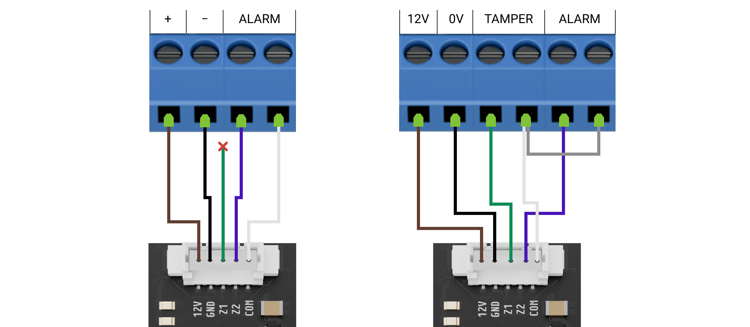
Superior Transmitter Fibra has two inputs (Z1 and Z2) to connect one wired device using the AATT (i.e., Alarm Alarm Tamper Tamper) scheme or two devices simultaneously.
- Turn on the lines power supply in the Ajax PRO app:
- Hub → Settings → Lines → Lines Power Supply.
- Hub → Settings
- Add Superior Transmitter Fibra to the hub.
- Add a wired device to the system.
- Run the module functionality testing.
Maintenance
Superior Transmitter Fibra does not require maintenance when mounted in the wired device casing.
Technical specifications
Warranty
Warranty for the Limited Liability Company “Ajax Systems Manufacturing” products is valid for 2 years after the purchase.
If the device does not function correctly, please contact Ajax Technical Support first. In most cases, technical issues can be resolved remotely.
Contact Technical Support:
Manufactured by “AS Manufacturing” LLC
