Superior MultiTransmitter G3 Jeweller is an integration module used to connect third-party wired devices to an Ajax system. It features 18 wired zones for connecting NC, NO, EOL, 2EOL, and 3EOL devices.
Superior MultiTransmitter G3 Jeweller has two tamper buttons that protect it against dismantling. The module is powered from the 100–240 V~ mains and can operate on a 12 V⎓ backup battery. Also, the module can supply 10.5–15 V⎓ for connected devices.
The integration module operates in an Ajax system and exchanges data with a hub via the secure Jeweller and Wings radio protocols.
Superior MultiTransmitter G3 Jeweller is a device of the Superior product line. Only accredited Ajax Systems partners can sell, install, and maintain Superior products.
Functional elements
Casing elements
- Screws to secure the casing lid. Use a bundled hexagon key (Ø 4 mm) to unscrew them.
- Light guide to indicate the integration module state.
- Part with holders for a backup battery.

A backup battery is not included.
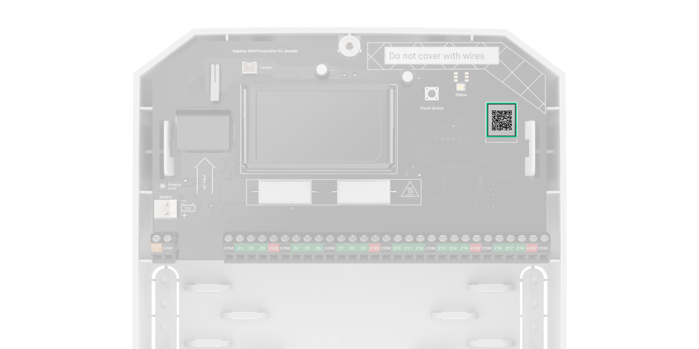
- QR code and ID (serial number) of the integration module.
- Perforated part of the casing. It is necessary for the tamper button to be triggered in case of any attempt to detach the device from the surface. Do not break it off.
- Perforated parts of the casing to route the wires of connected devices.
- Cable fasteners.
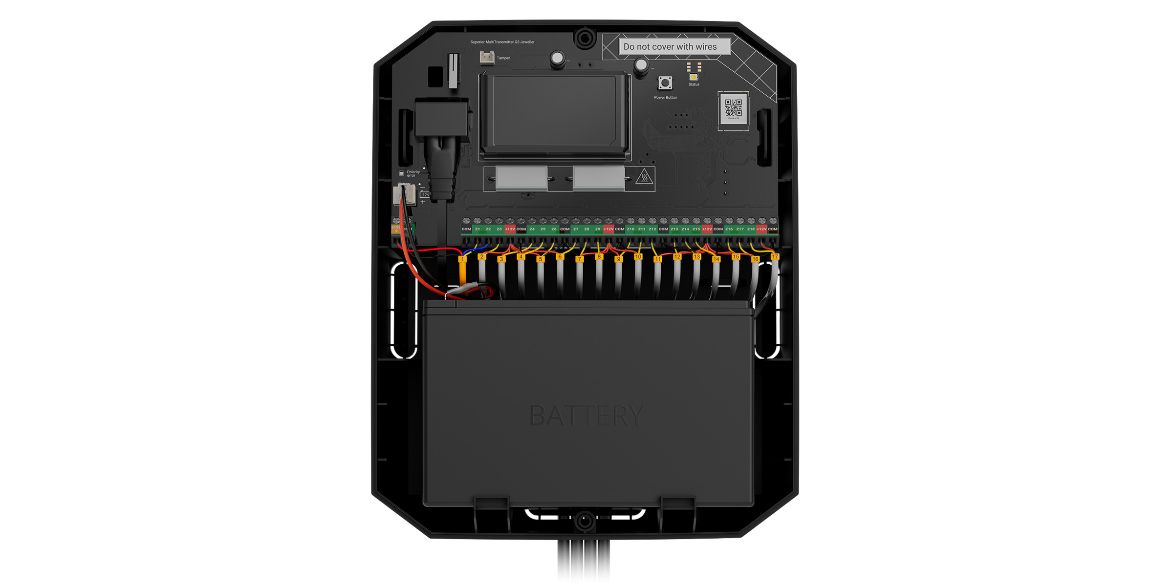
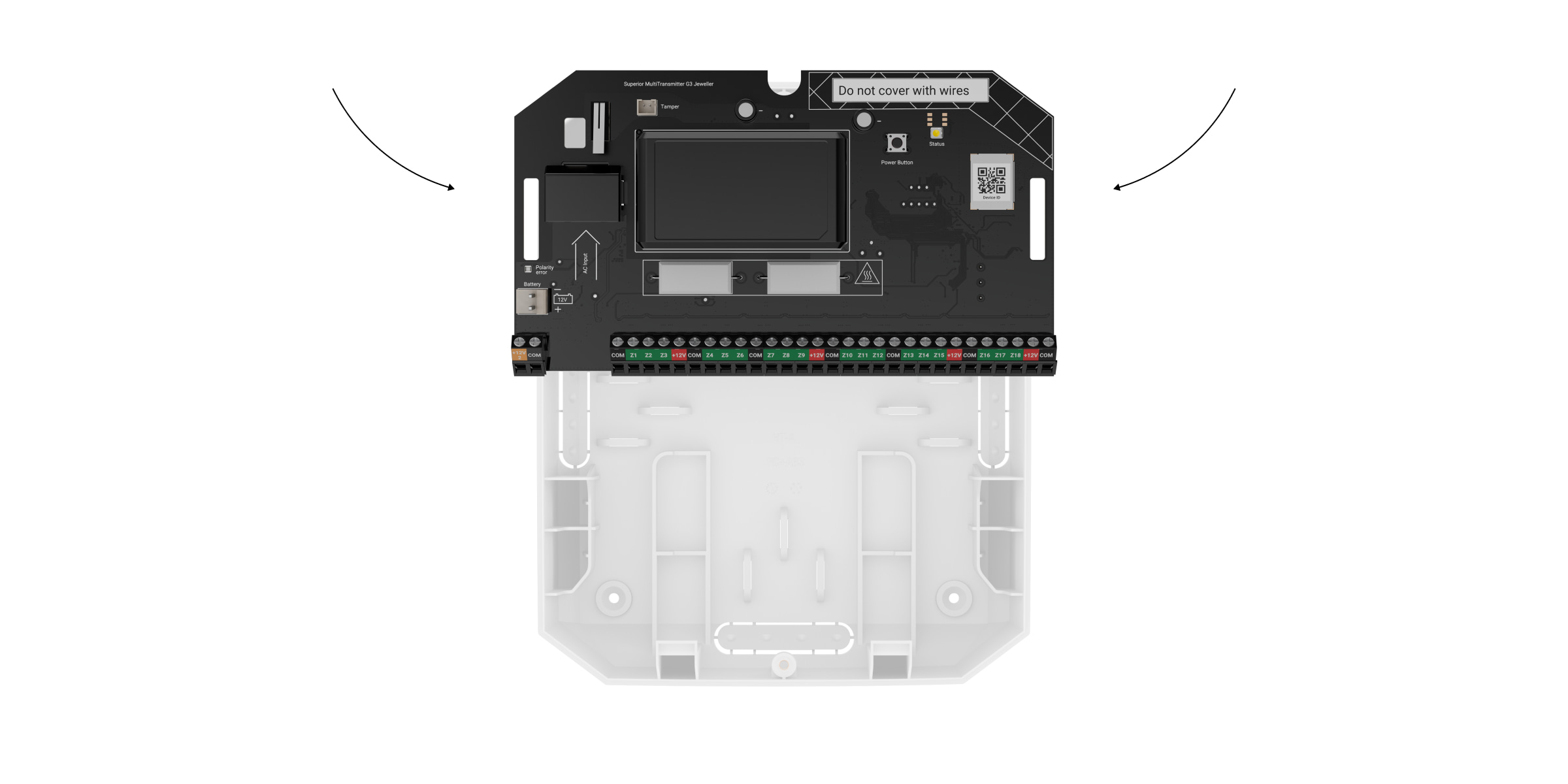
Board elements
- Terminals for connecting the power supply for fire detectors.
- Terminals for connecting a 12 V⎓ backup battery.
- Battery error indicator. It lights up if the battery is connected with reverse polarity (e.g., “–” is connected to “+” and vice versa).
- Power cable connector.
- Front-side tamper button. It detects attempts to remove the casing lid of the module.
- Connector for attaching a tamper board to the module. The tamper board is included in the Ajax Case complete set (the casing is sold separately).
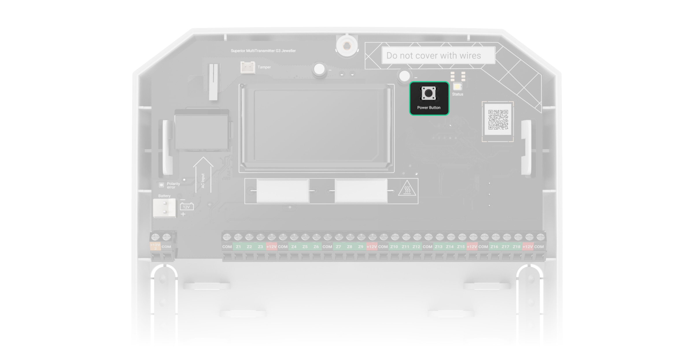
- Power button.
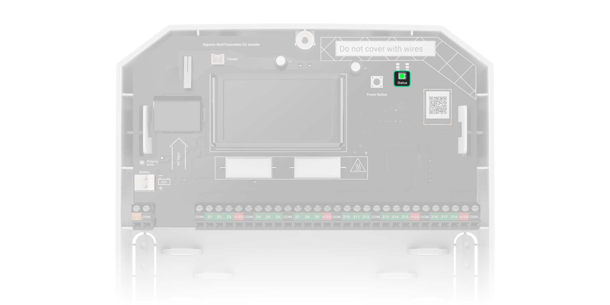
- LED indicator.
- QR code and ID (serial number) of the device.
- Mounting holes for installing the Superior MultiTransmitter G3 Jeweller board into the casing.
- Terminals for connecting third-party wired devices.
- Rear-side tamper button. It signals attempts to detach the module casing from the surface.
Terminals
Terminals on the left side of the board:
- +12V2 — 10.5–15 V⎓ power output for fire detectors, up to 0.4 A in total.
- COM — common input for connecting power supply circuits and signal contacts of wired devices.
Terminals on the right side of the board:
- Z1–Z18 — inputs for connecting wired devices.
- +12V — 10.5–15 V⎓ power output for wired devices, up to 1 A in total for all power supply outputs.
- COM — common input for connecting power supply circuits and signal contacts of wired devices.
Compatible hubs and range extenders
The integration module requires an Ajax hub running OS Malevich 2.36 or later.
Operating principle
Superior MultiTransmitter G3 Jeweller is designed to integrate third-party wired devices into an Ajax system. The integration module receives information about alarms, malfunctions, and events from devices through a wired connection. Then, it sends the event to the hub via the Jeweller wireless data transfer protocol. The hub in turn sends notifications to users and the monitoring station.
A wired device connected to Superior MultiTransmitter G3 Jeweller can operate in one of the following sensor modes:
- Detect alarms
- Switch arming modes
- Control of blocking element
- Control of bolt lock
Superior MultiTransmitter G3 Jeweller can be used to integrate alarm and auxiliary request alert buttons, indoor and outdoor motion detectors, as well as detectors that respond to door opening, vibration, glass breakage, fire, gas and water leakage, etc.
Also, you can set up KeyArm Zone that enables switching system security modes with a third-party device connected to Superior MultiTransmitter G3 Jeweller. KeyArm allows you to arm/disarm the system and individual groups or manage Night mode.
The device type is specified in the settings of the zone to which the wired device is connected. The selected type determines the text of alarm notifications and events of the connected device, as well as event codes transmitted to monitoring software.
Control of blocking element and Control of bolt lock sensor modes are used to integrate third-party blocking elements and bolt switch contacts into an Ajax system according to the unavoidability principle (German: Zwangsläufigkeit).
Types of wired devices
| Detect alarms operating mode | |||
| Event type | Icon | Meaning | |
| Tamper alarm |
 |
Event of a detector or device tamper triggering. | |
| Intrusion |
 |
Alarm when the motion, opening or other detector triggers. | |
| Fire |
 |
Alarm when fire detectors trigger. | |
| Auxiliary alarm |
 |
Alarm caused by pressing an auxiliary request button. | |
| Panic button |
 |
Alarm caused by pressing the alarm button. | |
| Gas alarm |
 |
Alarm when gas concentration is exceeded. | |
| Malfunction |
 |
Event of a connected detector or device malfunction. | |
| Leakage |
 |
Alarm caused by flooding. | |
| Glass break |
 |
Alarm when the glass break sensor is triggered. This event type operates only in Pulse operating mode. |
|
| High temperature |
 |
Alarm when the upper temperature limit is exceeded. | |
| Low temperature |
 |
Alarm when the lower temperature limit is exceeded. | |
| Masking |
 |
Alarm when the device masking is detected. | |
| Duress code (opening) |
 |
Alarm when the duress code is entered. This event type operates only in Pulse operating mode. |
|
| Vibration (seismic sensor) |
 |
Alarm when the seismic sensor is triggered. This event type operates only in Pulse operating mode. |
|
| Custom |
 |
The event type is customized by the user. Not sent to the security company monitoring station, and to users via SMS. |
|
| Switch arming modes operating mode | |||
| Icon | Meaning | ||
 |
You can set up KeyArm Zone that allows switching system security modes with a third-party device connected to Superior MultiTransmitter G3 Jeweller. KeyArm allows you to arm/disarm the system and individual groups or manage Night mode. If the Followed group feature is configured for groups, their security state can automatically change depending on their settings and initiators’ states. |
||
| Control of blocking element operating mode | |||
| Icon | Meaning | ||
 |
You can set up Control of blocking element that allows receiving notification of the third-party blocking element state. This feature is part of the unavoidability principle (German: Zwangsläufigkeit) flow. |
||
| Control of bolt lock operating mode | |||
| Icon | Meaning | ||
 |
You can set up Control of bolt lock that allows receiving notifications of the lock bolt state. This feature is part of the unavoidability principle (German: Zwangsläufigkeit) flow. |
||
Superior MultiTransmitter G3 Jeweller has 18 wired zones. It is recommended to connect one device to one zone.
The integration module has five 10.5–15 V⎓ power supply lines: one for fire detectors (up to 0.4 A) and four for other devices (up to 1 A in total for all power supply outputs).
After a fire alarm is activated, fire detectors need a power reset to restore normal operation. Therefore, the power supply of fire detectors must be connected to a dedicated line. Also, avoid connecting other devices to the fire detector power terminals, as this may cause false alarms or incorrect device operation.
Supported connection types:
- NO (normally open)
- NC (normally closed)
- EOL (connection with one resistor)
- 2EOL (connection with two resistors)
- 3EOL (connection with three resistors)
The device supports EOL with a resistance of 1 to 15 kΩ. The total resistance of all resistors is up to 30 kΩ. To increase protection against sabotage, EOL resistors with different resistances can be used in one detector. The recommended resistance ratio of EOL resistors: R1=R, R2=2R, R3=3R. For devices with solid-state relays or semiconductor switches, it is recommended to use R1 > 3 kΩ.
In an Ajax app, you can select the normal state (normally closed or normally open) for each terminal pair: alarm, tamper alarm, and malfunction. This allows connecting any potential-free contact detector to Superior MultiTransmitter G3 Jeweller.
Superior Jeweller data transfer protocol
Superior Jeweller is an upgraded radio protocol for Superior devices, ensuring compliance with EN 50131 (Grade 3). It features advanced encryption and frequency hopping. Full frequency hopping is available only when all devices in the system use Superior Jeweller. If at least one device operates via the regular Jeweller protocol, the system will be limited to Grade 2: encryption remains, but frequency hopping is disabled. Superior devices can also operate using the regular Jeweller protocol, depending on the hub.
Wings data transfer protocol
Wings is a proprietary wireless communication technology for transmitting large data packets. The integration module uses Wings to upload firmware updates.
Advanced encrypted communication
Communication between Superior MultiTransmitter G3 Jeweller and the hub is protected by an advanced encryption scheme that ensures data confidentiality and integrity. This means that all sensitive data in the message is encrypted, and each message includes a unique authentication tag allowing the system to verify that the data has not been modified during transmission. The system can reliably detect tampering and reject forged or altered messages, providing robust protection against both passive and active attacks. This ensures secure communication between the device and the hub, as well as reliable system and data protection.
Frequency hopping
To comply with the Grade 3 requirements, Superior MultiTransmitter G3 Jeweller uses frequency hopping for radio communication with the hub (or the radio signal range extender). With this method, the hub and devices added to it change their operating frequency according to a defined pattern. The hopping sequence covers a defined set of channels within the operating bands, and the devices switch frequencies synchronously with the hub. Even if some channels are affected by jamming, messages can be transmitted successfully via other channels. Frequency hopping improves the system’s reliability and performance and ensures its resistance to intentional interference and jamming attempts.
Frequency hopping does not cause delays or pauses during radio communication and does not reduce the data transfer speed. If range extenders are added to the system, frequency hopping is used for all radio communications: “device ↔ range extender” and “range extender ↔ hub”.
The system uses frequency hopping for radio communication only if all wireless devices support this method.
If at least one device added to the system does not support frequency hopping, the hub and all devices switch to the operating frequencies of that device and do not use frequency hopping for radio communication.
Firmware update
If a new firmware version for Superior MultiTransmitter G3 Jeweller is available, the ![]() icon appears in Ajax apps in the Devices
icon appears in Ajax apps in the Devices ![]() tab. An admin or a PRO with access to the system settings can run an update via device states or settings. The on-screen instructions help to update the firmware successfully.
tab. An admin or a PRO with access to the system settings can run an update via device states or settings. The on-screen instructions help to update the firmware successfully.
Sending events to the monitoring station
An Ajax system can transmit alarms to the Ajax PRO Desktop monitoring app and the monitoring station in the formats of SurGard (Contact ID), SIA (DC-09), ADEMCO 685, and other protocols.
Superior MultiTransmitter G3 Jeweller can transmit the following events:
- Integration module tamper alarm / restoration.
- Connected device alarm/restoration.
- Loss/restoration of connection between the integration module and the hub or radio signal range extender.
- Loss/restoration of connection between the integration module and the devices connected to it.
- Deactivation/activation of the integration module.
- Deactivation/activation of wired devices connected to the integration module.
- Unsuccessful attempt to arm a security system (if system integrity check is enabled).
When an alarm is received, the monitoring station operator knows what has happened and where to dispatch a rapid response unit. Ajax device addressability allows the system to send events to Ajax PRO Desktop and the monitoring station with the specified device type, name, security group, and virtual room. The list of transmitted parameters may vary depending on monitoring software and the selected communication protocol.
You can find the device ID and loop (zone) number in the device states. The device number corresponds to the loop (zone) number.
Selecting the installation site

Superior MultiTransmitter G3 Jeweller is designed for indoor installation. We recommend choosing the installation location hidden from eyes.
When choosing a location for installing Superior MultiTransmitter G3 Jeweller, consider the parameters that affect its operation:
- Jeweller and Wings signal strength
- Cable length for connecting wired devices to Superior MultiTransmitter G3 Jeweller
You must consider the placement recommendations when designing the system for the facility. Only specialists can design and install an Ajax system. A list of recommended partners is available here.
Signal strength
The Jeweller signal strength is determined by the number of undelivered or corrupted data packets over a certain period of time. The icon ![]() in the Devices
in the Devices ![]() tab in Ajax apps indicates the signal strength:
tab in Ajax apps indicates the signal strength:
- three bars — excellent signal strength;
- two bars — good signal strength;
- one bar — low signal strength; stable operation is not guaranteed;
- crossed-out icon — no signal.
Check the Jeweller and Wings signal strength before final installation. With a signal strength of one or zero bars, we do not guarantee the module’s stable operation. Consider relocating the module, as repositioning even by 8 inches can significantly improve the signal strength. If the signal is still poor or unstable after relocation, use a radio signal range extender.
Refer to the Functionality testing section to learn how to run the Jeweller and Wings signal strength test.
Where not to install the integration module
- Outdoors. This may cause the module to malfunction.
- In places with temperature and humidity beyond the permissible limits. This may damage the module.
- Closer than 3 ft to the hub (or the radio signal range extender).
- In places with low or unstable Jeweller or Wings signal strength.
Preparing for installation
Cable arrangement
Carefully read the user manual for the third-party wired detector or device before connecting it to Superior MultiTransmitter G3 Jeweller. If you have any questions, please contact the technical support of the device manufacturer.
Violation of the basic installation rules, the recommendations of this manual, and the instructions of the manufacturers of third-party wired devices may result in their incorrect operation and false alarms.
When planning where to install the integration module or connected wired devices, consider the wiring diagram of the power cables at the facility. Signal cables for security system devices must be laid at a distance of at least 20 inches from the power cables in case of parallel routing. If cables intersect, keep the 90° angle.
For facilities under construction or renovation, cables are laid after the facility electrical wiring is installed. Use protective tubes, ties, clips, and staples to organize and secure the cables. Make sure that the fasteners do not damage the cables or their insulation during installation.
When laying cables externally (without mounting them inside the walls), use an electric channel raceway. Raceways should be no more than half-filled with cables. Do not allow cables to sag. The raceway should be hidden from view if possible — for example, behind furniture.
We recommend laying cables inside the walls, floors, and ceilings. This will provide greater security: the cables will not be visible, and it will be impossible for an intruder to access them.
When installing, observe the bend radius that the manufacturer specifies in the cable specs. Otherwise, you risk damaging or breaking it.
Before installation, check all cables for bends and physical damage. Perform the installation in a way that minimizes the possibility of damage to the cables from the outside.
Cable specifications for connected devices
We recommend using copper-clad aluminum signal cable with a cross-section of 0.22 mm² (approx. 24 AWG).
The maximum length of the signal cable used to connect third-party devices to Superior MultiTransmitter G3 Jeweller is 1,300 ft. However, the maximum length may vary depending on the cable type and the requirements of the third-party device manufacturer. No other types of cables have been tested.
To check specific cable requirements, refer to the user manual of the device that will be connected to the module.
Preparing cables for connection
Remove the insulating layer and strip the cable with a special insulation stripper. The wire ends inserted into the device terminals must be tinned or crimped with a sleeve. This ensures a reliable connection and protects the conductor from oxidation.
To check specific cable preparation requirements, refer to the user manual of the device that will be connected to Superior MultiTransmitter G3 Jeweller. Follow these requirements to ensure stable operation of the device.
Installation
Before installing Superior MultiTransmitter G3 Jeweller, ensure you have selected the optimal location that complies with the requirements of this manual.
Secure the integration module to a vertical surface. Vertical installation is needed for the tamper button to respond if someone attempts to detach the module. Before installation, refer to battery documentation — some batteries can be mounted only vertically (with terminals facing upward). Any other installation position may result in rapid battery degradation.
Installing the module
- De-energize the cables you will connect to Superior MultiTransmitter G3 Jeweller.
- Remove the module board from its casing by pushing the latches and pulling the module board.
- Prepare the holes for routing the cables in the casing. Carefully break off the required perforated parts of the module casing.

- Run the module power cable and the wired device cables into the module casing through the prepared holes.
- Using all fixing points, secure the module casing to a vertical surface at the selected installation site with the bundled screws. One of these points is located in the perforated part above the tamper button: if someone attempts to detach the integration module, the tamper button will be triggered.

- Install the Superior MultiTransmitter G3 Jeweller board into the casing on the holders.
- Connect wired devices to the integration module, securely fixing the wires in the terminals. The wiring diagram is provided in the user manual supplied by the wired device manufacturer.
If the wired device requires a 12 V⎓ power supply, it can be connected to the power terminals of the corresponding integration module’s zone. Separate power terminals are provided for fire detectors.Use separate wires to connect the signal contact and power supply circuits of the wired device to the module’s COM terminal. Two wires can be connected to one terminal.Read the manufacturer’s instructions before connecting the device to the integration module.
- Install the battery in the designated holders provided in the casing.
We recommend using a 12 V⎓ battery with 4 or 7 Ah capacity. For such batteries, there are special racks in the casing. You can also use similar batteries with different capacities if their size fits the casing and the maximum full charge time does not exceed 24 hours. The maximum dimensions of the battery that can be installed in the casing are 5.94″ × 2.55″ × 3.70″, and the maximum weight is 11 lb.
- Connect the backup battery to the corresponding module terminal using the bundled cable. Observe the correct polarity and wiring order. Note that third-party power supply units cannot be connected to the terminals.
- Connect the power cable to the corresponding connector.
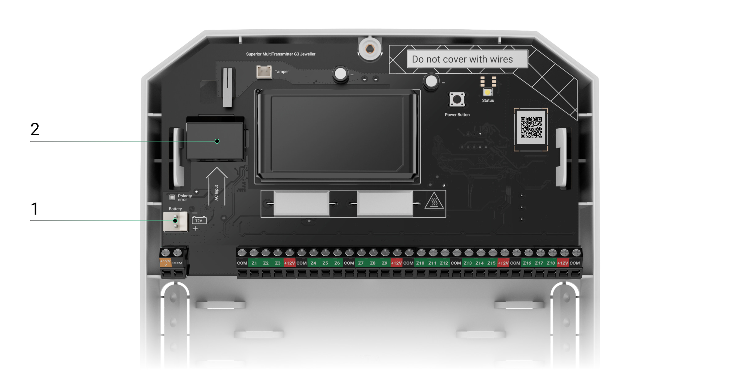
1 — battery connector
2 — power cable connector - Secure the cables with cable ties.

- Add Superior MultiTransmitter G3 Jeweller to the hub.
- Add the connected wired devices to the system.
- Install the front lid on the module and fasten it with the bundled screws.
- Run the module functionality test.
Connecting wired devices to the module
The following steps describe how to connect wired devices to the integration module that has already been installed and added to the system. If the module has not been installed yet, refer to the Installing the module section.
- Unscrew the module’s front lid and remove it.
- Turn off the integration module by holding down the power button.
- Disconnect the 100—240 V~ external power supply and the backup battery.
- Select the integration module’s zone to which you want to connect a device.
- Pull the third-party device cable into the integration module casing.
- Connect the device to the integration module, securely fixing the wires in the terminals. The wiring diagram is provided in the user manual supplied by the wired device manufacturer.
If the wired device requires a 12 V⎓ power supply, it can be connected to the power terminals of the corresponding integration module’s zone. Separate power terminals are provided for fire detectors.Use separate wires to connect the signal contact and power supply circuits of the wired device to the module’s COM terminal. Two wires can be connected to one terminal.Read the manufacturer’s instructions before connecting the device to the integration module.
- Secure the cable with cable ties using special fasteners inside the module casing.
- Connect the 100—240 V~ external power supply and backup battery to the integration module.
- Turn on the integration module by holding down the power button.
- Add the connected wired devices to the system.
- Test the operation of the connected wired device.
- Install the front lid on the module and fasten it with the bundled screws.
Adding to the system
Wired devices can be connected to Superior MultiTransmitter G3 Jeweller both before adding the module to the hub and after that.
The hub and the device operating at different radio frequencies are incompatible. The device’s radio frequency range may vary by region. We recommend purchasing and using Ajax devices in the same region. The technical support service can help you check the operating frequency range.
Check the device compatibility before adding the integration module to the system. Superior MultiTransmitter G3 Jeweller is a device of the Superior product line. Only accredited Ajax Systems partners can sell, install, and maintain Superior products.
Before adding the module
- Install an Ajax PRO app.
- Log in to your PRO account or create a new one.
- Select a space or create a new one.
- Add at least one virtual room.
- Add a compatible hub to the space. Ensure the hub is switched on and has internet access via Ethernet, Wi-Fi, and/or mobile network.
- Check the states in the Ajax app to ensure the space is disarmed and the hub is not starting an update.
Adding the module to the hub
- Open an Ajax PRO app. Select a space to which you want to add the integration module.
- Go to the Devices
 tab and tap Add device.
 - Assign a name to the integration module.
- Scan a QR code or enter the device ID manually. The QR code with the device ID is placed on the module board and on the back of the casing. Also, it is duplicated on the device packaging.
- Select a virtual room and a security group (if Group mode is enabled).
- Tap Add, and the countdown will begin.
- Switch on the integration module by holding the power button for 3 seconds.
Note that a request to connect to the hub is sent at the very moment the integration module is turning on. If the connection fails, turn off the module for 5 seconds and try again. If the maximum number of devices has already been added to the hub, the system will send an error notification when you try to add more.
Once added to the hub, the integration module will appear in the list of hub devices in the Ajax app. The interval for updating device states in the list depends on the Jeweller or Jeweller/Fibra settings and is 36 seconds by default.
Superior MultiTransmitter G3 Jeweller works with only one hub. When the integration module is added to a new hub, it stops sending events to the old one. However, the integration module remains in the old hub device list and must be removed manually in the Ajax app.
Adding a connected wired device
In the Ajax system, each device connected to Superior MultiTransmitter G3 Jeweller occupies one slot within the hub’s device limit.
- In an Ajax app, go to the Devices tab.
- Find Superior MultiTransmitter G3 Jeweller in the list.
- Select Devices under the module icon.
- Tap Add device.
- Assign a name to the device.
- Select the wired input to which the device is physically connected.
- Select a virtual room.
- Tap Add device. The device will be added within 30 seconds.
The device state update interval depends on the Jeweller or Jeweller/Fibra settings; the default value is 36 seconds.
If the connection attempt fails, ensure the wired connection is correctly set up before trying again. If the maximum number of devices has already been added to the hub, an error notification will appear when you try to add another device.
To perform the detection test, trigger the connected third-party device (for example, motion for motion detectors, etc.) The state of the third-party detector will be displayed in the app and on the device’s LED indicator if it is available.
Module functionality testing
An Ajax system provides several tests to help you select the correct installation place for the devices. For Superior MultiTransmitter G3 Jeweller, the following tests are available:
- Jeweller signal strength test — to determine the signal strength and stability between the hub (or the radio signal range extender) and the integration module via the wireless Jeweller data transfer protocol at the installation site.
- Wings signal strength test — to determine the signal strength and stability between the hub (or the radio signal range extender) and the integration module via the wireless Wings data transfer protocol at the device installation site.
- Signal attenuation test — to decrease or increase the power of the radio transmitter. The test allows users to check communication stability between the integration module and the hub by simulating the changing environment at the site.
Icons
The icons in an Ajax app display some of the Superior MultiTransmitter G3 Jeweller states and the states of the connected devices. The icons can be checked in the Devices ![]() tab.
tab.
Module icons
| Icon | Meaning |
|
Jeweller signal strength. It displays the signal strength between the hub and the module. The recommended value is 2–3 bars. |
|
| A fire detector connected to the integration module has registered an alarm. | |
|
Backup battery charge level. |
|
| A backup battery is not connected. | |
| A firmware update is available. Go to the module states or settings to find the description and launch an update. | |
| Firmware update is in progress: downloading/installing the latest version. | |
|
The module operates via the radio signal range extender. |
|
|
The module is in the Signal attenuation test mode. |
|
|
The module is permanently deactivated. |
|
|
Tamper alarm notifications are permanently deactivated. |
|
|
The module is deactivated until the system is disarmed. |
|
|
Tamper alarm notifications are deactivated until the system is disarmed. |
|
| The module has lost connection to the hub, or the hub has lost connection to the Ajax Cloud server. | |
|
The module has not been transferred to the new hub. |
Icons of connected devices
| Icon | Meaning |
|
The Chime feature is enabled. |
|
|
|
Entry/Exit delay is enabled. |
|
The device operates in Always active mode. |
|
|
The device will operate when Night mode is enabled. |
|
|
Reporting to the monitoring station is deactivated for the device. |
|
|
The device state is OK. Displayed for EOL, NC, and NO connections only. |
|
|
The device is short-circuited. Displayed for EOL, NC, and NO connections only. |
|
| The device tamper state is OK.* | |
| Device tamper alarm.* | |
| The state of the intrusion sensors is OK.* | |
| Intrusion alarm.* | |
| The state of the auxiliary button is OK.* | |
| Alarm when the auxiliary button is pressed.* | |
| The state of the panic button is OK.* | |
| Alarm when the panic button is pressed.* | |
| The state of the fire sensor is OK.* | |
| The device has detected a fire alarm.* | |
| The state of the gas sensor is OK.* | |
| Alarm when the gas concentration is exceeded.* | |
| The device state is OK.* | |
| Device malfunction is detected.* | |
| The state of the leak sensor is OK.* | |
| Alarm caused by the flooding.* | |
| The state of the glass break sensor is OK.* | |
| Glass break alarm.* | |
| The state of the high temperature sensor is OK.* | |
| Alarm when the upper temperature limit is exceeded.* | |
| The state of the low temperature sensor is OK.* | |
| Alarm when the lower temperature limit is exceeded.* | |
| The state of the masking sensor is OK.* | |
| Masking alarm.* | |
| The state of the duress code device is OK.* | |
| Alarm caused by the system disarming using the duress code device.* | |
| The state of the vibration (seismic) sensor is OK.* | |
| Vibration (seismic) alarm.* | |
| The state of the device for which the custom type of event is selected is OK.* | |
| The alarm of the device for which the custom type of event is selected.* | |
| The sensor operates in the Switch arming modes mode.* | |
| The state of the Blocking element.* | |
| The state of the Bolt lock.* | |
|
The device is automatically disabled due to exceeding the number of alarms. |
|
|
The device is automatically disabled by the restoration timer. |
|
|
The device is disabled by the system user. |
|
|
The device is disabled until the first event of disarming the system. |
* Icon is displayed for 2EOL and 3EOL connections only.
States
Module states
The states include information about the integration module and its operating parameters. The states of Superior MultiTransmitter G3 Jeweller can be found in Ajax apps:
- Go to the Devices tab.
- Select Superior MultiTransmitter G3 Jeweller in the list.
| Parameter | Meaning |
| Data import | Displays an error during data transfer to the new hub:
|
| Firmware update | Shows the state of the firmware update if a new version is available:
|
| Malfunction |
If you tap The field is displayed only if a malfunction is detected. |
| Jeweller signal strength |
Signal strength between the module and the hub (or the range extender) via the Jeweller channel. The recommended value is 2–3 bars. Jeweller is a protocol for transmitting events and alarms. |
| Connection via Jeweller | Connection status between the module and the hub (or the range extender) via Jeweller channel:
|
| Wings signal strength |
Wings signal strength between the module and the hub (or the range extender). The recommended value is 2–3 bars. Wings is a protocol for updating the device firmware. |
| Connection via Wings | Connection status via Wings channel between the module and the hub (or the range extender):
|
| <Range extender name> | State of module connection to the radio signal range extender:
The field is displayed if the module operates via the radio signal range extender. |
| Transmitter power |
Displays the selected transmitter power. The field is displayed when the Max or Attenuation option is selected in the Signal attenuation test menu. |
| Battery charge |
The charge level of the connected battery. Specified as a percentage in 5% increments. |
| Lid | State of the tamper button that is triggered when the module is detached from the surface or the integrity of the casing is compromised:
|
| Tamper board | State of the Case’s tamper board connected to the integration module board:
|
| External power | External power supply connection state:
|
| Detector power line | Power line state of third-party wired devices:
|
| Fire detector power line | Power line state of third-party fire detectors:
|
| Advanced encryption | The state of the communication with advanced encryption between the device and the hub or radio signal range extender:
|
| Permanent deactivation | The field shows the state of the module’s permanent deactivation setting:
|
| One-time deactivation | The field shows the state of the device’s one-time deactivation setting:
|
| Firmware | Module firmware version. |
| Device ID | Module ID. It is also available on the QR code on the back of the casing, on the board, and on module packaging. |
| Device No. | Module number. It is transmitted to the monitoring station if there is an alarm or event in the system. |
States of connected devices
The states display information about the connected devices and their operating parameters. You can find the states of the devices connected to Superior MultiTransmitter G3 Jeweller in Ajax apps:
- Go to the Devices tab.
- Select Superior MultiTransmitter G3 Jeweller in the list.
- Select Devices under the Superior MultiTransmitter G3 Jeweller icon.
- Select the device from the list.
| Parameter | Meaning |
| Malfunction |
Tapping on the The field is displayed only if a malfunction is detected. |
| Name of connected wired device | Connection status on the line between Superior MultiTransmitter G3 Jeweller and connected wired device:
|
| Device state | Status of the connected wired device:
|
|
“Name of the selected event type” Sensor 1 Displayed for 2EOL and 3EOL connection types |
State of the connected wired device:
|
|
Arm switch state Displayed for 2EOL and 3EOL connection types when the Switch arming modes option is selected for Sensor mode (for Sensor 2). |
State of the connected wired device:
|
|
Blocking element state Displayed for 2EOL and 3EOL connection types when the Control of blocking element option is selected for Sensor mode (for Sensor 2). |
State of the connected blocking element:
|
|
Bolt lock state Displayed for 2EOL and 3EOL connection types when the Control of bolt lock option is selected for Sensor mode (for Sensor 2). |
State of the connected bolt lock:
|
| Always active |
If the option is enabled, the device connected to the integration module is constantly armed and reports alarms. You can configure the option only for certain event types. |
|
Device resistance Displayed for EOL, 2EOL, and 3EOL connection types |
The total resistance of the resistor(s) connected to the device is measured automatically. Values can also be set manually in increments of 100 Ω. |
| Permanent deactivation |
Allows a user to disable the device without removing it from the system. Two options are available:
You can also separately configure the device disconnection:
The feature is configured in Ajax PRO apps. |
| One-time deactivation | Status of the device one-time deactivation setting:
|
| Alarm reaction | |
| Operating mode | Shows how the device responds to alarms:
|
| Entry delay |
Entry delay (alarm activation delay) is the time a user has to disarm the system after entering the premises. |
| Exit delay |
Exit delay (arming delay) is the time a user has to leave the premises after the system is armed. |
| Arm in Night mode |
If this option is enabled, the device will enter armed mode when the system is set to Night mode. |
| Entry delays in Night mode |
Entry delay in Night mode. Entry delay (alarm activation delay) in Night mode is the time a user has to disable Night mode after entering the premises. |
| Exit delays in Night mode |
Exit delay in Night mode. Exit delay (arming delay) in Night mode is the time a user has to leave the premises after Night mode is enabled. |
| Night mode delay |
Entry delay in Night mode when the device is set to the Follower operating mode. It is the time a user has to disable Night mode (alarm activation delay) after the Entry/Exit detector is triggered. |
| Wired input | The Superior MultiTransmitter G3 Jeweller zone number to which a wired device is connected. |
| Device No. | The device loop (zone) number. |
Settings
Module settings
To change Superior MultiTransmitter G3 Jeweller settings, in an Ajax app:
- Go to the Devices tab.
- Select Superior MultiTransmitter G3 Jeweller in the list.
- Go to Settings
 .
. - Set the required parameters.
- Tap Back to save the new settings.
| Setting | Meaning |
| Name |
Integration module name. It is displayed in the list of hub devices, SMS, and notifications in the event feed. To change the name, tap on the text field. The name can contain up to 24 Latin characters or up to 12 Cyrillic characters. |
| Room |
Selecting the virtual room to which the integration module is assigned. The room name is displayed in SMS and notifications in the event feed. |
|
Device operation: Stop battery charging if faulty |
When the option is enabled, the module automatically stops charging a backup battery in case of malfunction. |
|
Device operation: Check device lid state when arming |
When the option is enabled, the system checks the device lid state during arming. When the option is disabled, the system disregards the device lid state during system integrity check and does not show a malfunction badges. The setting can be used in cases when the device is installed in Ajax Case and not connected to its tamper board. |
|
Notifications: Notify if battery fails to charge |
When the option is enabled, a user will receive a notification if the battery has not been fully charged for a long time. This option is enabled by default. |
|
Notifications: Notify if battery failed load test |
When the option is enabled, a user will receive a notification that the module backup battery cannot sustain the load. |
|
LED indication settings: LED brightness |
The setting allows a user to adjust the brightness of the module’s LED indicator. |
|
Alert with siren: If any connected device has power supply shorted out |
When the option is enabled, the sirens connected to the system will be activated when a short circuit is detected in the power supply line of devices connected to the integration module. |
| Firmware update | Allows a user to switch the module to the firmware updating mode if a new version is available. |
| Jeweller signal strength test |
Allows a user to switch the module to the Jeweller signal strength test mode. The test allows you to check the signal strength between the hub (or the radio signal range extender) and the module via the wireless Jeweller data transfer protocol to select the optimal installation site. |
| Wings signal strength test |
Allows a user to switch the module to the Wings signal strength test mode. The test allows you to check the signal strength between the hub (or the radio signal range extender) and the module via the wireless Wings data transfer protocol to select the optimal installation site. |
| Signal attenuation test |
Allows a user to switch the module to the Signal attenuation test mode. |
| User manual | Allows a user to open the Superior MultiTransmitter G3 Jeweller user manual in the Ajax app. |
| Permanent deactivation |
Allows a user to disable events of the module without removing it from the system. Three options are available:
|
| One-time deactivation |
Allows a user to disable module events until the system is disarmed. Three options are available:
|
| Delete device | Allows a user to disconnect the module from the hub. |
Settings of connected devices
To change the connected device settings, in an Ajax app:
- Go to the Devices tab.
- Select Superior MultiTransmitter G3 Jeweller in the list.
- Select Devices under the Superior MultiTransmitter G3 Jeweller tile.
- Select the device from the list.
- Go to Settings .
- Configure the required settings.
- Tap Back to save the new settings.
| Setting | Meaning |
| Name |
Wired device name. Displayed in the list of hub devices, SMS text, and notifications in the event feed. To change the name, tap on the text field. The name can contain up to 24 Latin characters or up to 12 Cyrillic characters. |
| Room |
Selecting the device’s virtual room. The room name is displayed in the text of SMS and notifications in the event feed. |
| Input type | Selecting the connection type of a third-party device:
|
| Sensor mode | Selecting the sensor mode of the connected device:
|
| Type of event |
Selecting an event type for the connected device. Refer to the Event types section for more information. The text of notifications in the event feed and SMS, as well as the code transmitted to the monitoring software, depends on the selected event type. This setting is available if the Detect alarms option is selected for the Sensor mode setting. |
| Arm switch settings |
Configuring the arm switch if the Switch arming modes option is selected for the Sensor mode setting:
|
| Default state | Selecting the normal contact state of the connected device:
|
| Operating mode | The operating mode of the connected device:
Be sure to set a type that matches the connected device. A pulsed detector in the bistable mode generates unnecessary restoration events. A bistable detector in pulsed mode, on the contrary, will not send restoration events. |
| Always active |
If the option is enabled, the device connected to the integration module is constantly armed and reports alarms. You can configure the option only for certain event types. This setting is not available if the Switch arming modes option is selected for the Sensor mode setting. |
| Notify of changes in bolt lock state |
If the option is enabled, the system will notify the user each time the bolt lock changes its state. This option is available if the Control of bolt lock option is selected for the Sensor mode setting. |
| Pulse time | Pulse time of the device for detecting an alarm:
An alarm will be activated if the pulse from the device lasts longer than specified in this setting. This can be used to filter out false alarms. |
| Event sending interval |
Available with OS Malevich 2.37 and later versions and Superior MultiTransmitter G3 Jeweller with firmware versions 5.66.2.2. Set the minimum time between events transmitted from a third-party device to the hub. The interval can be set from 5 seconds to 10 minutes*. *For compliance with EN 50131, the value must not exceed 10 seconds. |
| Alert with siren if alarm detected |
If the option is enabled, the sirens connected to the system are activated when an alarm is detected. This setting is available if the Detect alarms option is selected for the Sensor mode setting. |
| Chime settings |
Opens the Chime settings. The feature is available only for bistable devices. Notifications will not work for sensors in pulse mode or Always active mode. |
| Alarm response | |
| Operating mode | Specifies how this device will respond to alarms:
This setting is available if the Detect alarms option is selected for the Sensor mode setting. |
| Entry delay |
Entry delay: 5 to 255 seconds. Entry delay (alarm activation delay) is the time a user has to disarm the system after entering the premises. |
| Exit delay |
Exit delay: 5 to 255 seconds. Exit delay (arming delay) is the time a user has to leave the premises after the system is armed. |
| Arm in Night mode |
When this option is enabled, the detector will enter the armed mode if the system is set to Night mode. |
| Entry delays in Night mode |
Entry delay in Night mode: 5 to 255 seconds. Night mode entry delay (alarm activation delay) is the time a user has to disable Night mode after entering the premises. |
| Exit delays in Night mode |
Exit delay in Night mode: 5 to 255 seconds. Night mode exit delay (arming delay) is the time a user has to leave the premises after enabling Night mode. |
| Night mode delay |
Delay time in Night mode: 5 to 255 seconds. It is the time a user has to disable Night mode (alarm activation delay) after the Entry/Exit detector is triggered. The setting is displayed if the device is set to the Follower operating mode and the Arm in Night mode option is enabled. |
| Monitoring | Opens the Monitoring settings menu:
The Monitoring settings are available in the Ajax PRO apps only. |
| Permanent deactivation |
Allows a user to disable the device without removing it from the system. Two options are available:
You can also configure the device disconnection separately:
The feature is configured in Ajax PRO apps. |
| One-time deactivation |
Allows a user to disable events of the device until the first event of disarming the system occurs. Two options are available:
|
Chime on opening or doorbell button press
Chime is an audio signal that informs about the triggering of the opening detectors when the system is disarmed. The feature is used, for example, in stores to notify employees that someone has entered the premises.
The notifications are configured in two stages: setting up the sirens and setting up the opening detectors.
Configuring a wired opening detector connected to the module
Before setting up the Chime feature, make sure that a wired opening detector is connected to Superior MultiTransmitter G3 Jeweller and the following options have been configured in the detector settings in the Ajax app:
- Type of event — Intrusion
- Operating mode — Bistable
- Always active — disabled
- Go to the Devices tab.
- Find Superior MultiTransmitter G3 Jeweller in the list.
- Tap Devices under the Superior MultiTransmitter G3 Jeweller tile.
- Select the required device in the list.
- Go to its device Settings .
- Select the Chime settings option.
- Enable the If device is triggered option.
- Adjust the chime sound: 1 to 4 short beeps. Once selected, the Ajax app will play the sound.
- Tap Back to apply the settings.
Also, ensure the Chime feature is enabled for the required siren in its Beep settings.
Resetting fire alarms
When fire detectors connected to Superior MultiTransmitter G3 Jeweller are triggered, an Ajax app displays notifications prompting to reset the alarms. The reset returns the detectors to their normal state so that they can continue to detect fire.
If you do not reset the fire alarm, the detectors will not respond to the next fire, as they will remain in alarm mode.
There are two ways to reset fire alarms:
- Tap Reset in the fire alarm notification in the app.
- Go to Devices and find Superior MultiTransmitter G3 Jeweller in the list. Tap
 and then tap Reset to confirm the fire alarm reset.
Indication
The Superior MultiTransmitter G3 Jeweller LED indicator may light up in white, red, or green depending on the device state.
If Superior MultiTransmitter G3 Jeweller is not added to the hub or has lost connection with it, the integration module will not indicate the battery status or the presence of external power.
| Event | Indication | Note |
| Stable communication with the hub. The external power is connected. | Lights up in white. | |
| Communication with the hub is lost. External power is connected. | Lights up in red. | For example, the hub is disabled or the integration module is out of the hub radio network coverage. |
| Disabling integration module. | Goes out for 0.5 seconds, then lights up in green and turns off. | |
| The integration module has not been added to the hub. | Flashes red once per second. | |
| The integration module has no external power supply. | Lights up once a second every 10 seconds. |
Lights up in white if the integration module has communication with the hub. Lights up in red if there is no communication with the hub. |
| The integration module has no external power supply, and an external battery is discharged. | In case of alarm, it lights up smoothly and goes out once every 10 seconds. |
Lights up in white if the integration module has communication with the hub. Lights up in red if there is no communication with the hub. |
Malfunctions
When the Superior MultiTransmitter G3 Jeweller detects a malfunction (for example, there is no connection via the Jeweller protocol), a malfunction counter is displayed in the upper left corner of the device icon in an Ajax app.
All malfunctions can be seen in the module states and the states of connected devices. Fields with malfunctions will be highlighted in red.
A malfunction of Superior MultiTransmitter G3 Jeweller is displayed if:
- The integration module casing is open or dismantled from the surface (the tamper button has been triggered).
- There is no connection to the hub or radio signal range extender via Jeweller.
- There is no connection with the hub or radio signal range extender via Wings.
- The battery is discharged.
- The battery charges for more than 24 hours.
- Failed to connect a backup battery (the battery is not connected or there are hardware problems, such as a faulty connection cable).
- The wired device power supply line is shorted out.
A malfunction of the connected device is displayed if:
- The enclosure of the device is open (tamper triggering).
- No connection between the integration module and the device (contacts are damaged).
- Incorrect connection of resistors (resistance of resistor error).
- The system has detected a short circuit in the device contacts.
The system can report malfunctions to the monitoring company, as well as to users via push notifications and SMS.
Maintenance
Check the functionality of the integration module and the connected wired detectors and devices on a regular basis. The optimal interval for the check is once every three months. It is recommended to check that the wires are tightly fixed and connected to the terminals of the integration module.
Clean the casing from dust, cobwebs, and other contaminants as they emerge. Use a soft dry cloth that is suitable for equipment care. Do not use any substances containing alcohol, acetone, gasoline, and other active solvents to clean the device.
Technical specifications
Warranty
The warranty for the products of the “Ajax Systems Manufacturing” Limited Liability Company is valid for 2 years after purchase.
If the device does not operate properly, we recommend contacting support service first, as most technical issues can be resolved remotely.
Contact Technical Support:
Manufactured by “AS Manufacturing” LLC
