Superior MotionProtect Plus G3 Fibra is a wired motion detector. It detects movement at a distance of up to 49 ft. In addition to using the IR sensor, the detector applies an additional radio frequency scan with a K-band microwave sensor that filters out infrared interference. Also, it features an anti-masking system that detects attempts to block the detector’s field of view. The device is designed for indoor use only and complies with EN 50131 (Grade 3) requirements.
Superior MotionProtect Plus G3 Fibra is compatible with Superior Hub Hybrid (2G) and Superior Hub Hybrid (4G). Connection to other hubs, radio signal range extenders, ocBridge Plus, and uartBridge is not provided.
The detector exchanges data with the hub using the secure Fibra wired communication protocol. Wired communication can be up to 6,550 ft long when connected using the U/UTP cat.5 twisted pair cable.
Superior MotionProtect Plus G3 Fibra is a part of the Superior product line of wired devices. Only accredited Ajax Systems partners can sell, install, and administer Fibra products.
Functional elements

- LED indicator.
- Detector’s IR motion sensor sensitive area.
- Masking sensor.
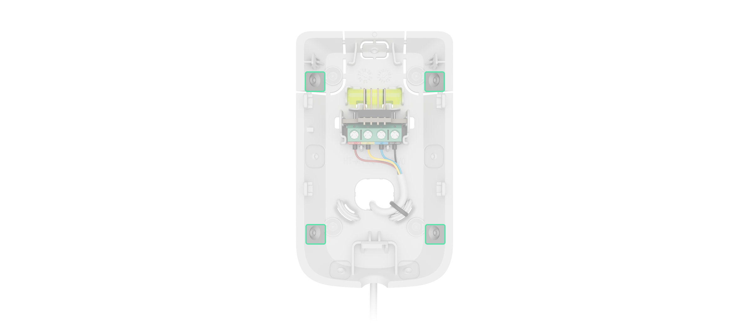
- SmartBracket mounting panel. To remove the panel, slide it down.
- Perforated parts of the mounting panel. Trigger a tamper in case of any attempt to detach the device from the surface. Do not break them off.
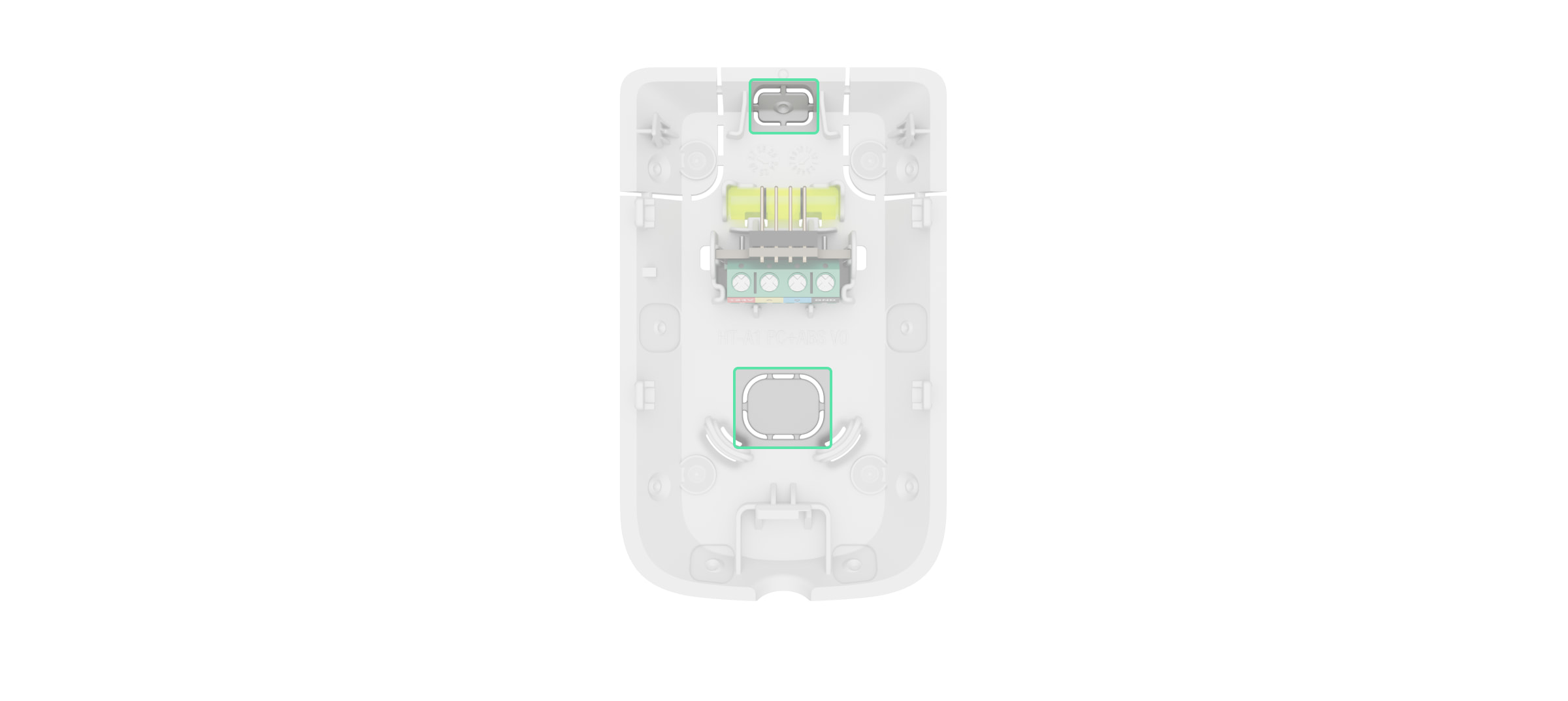
- Perforated part of the mounting panel for routing cables from the top of the device.
- Perforated part of the mounting panel for routing cables through the wall.
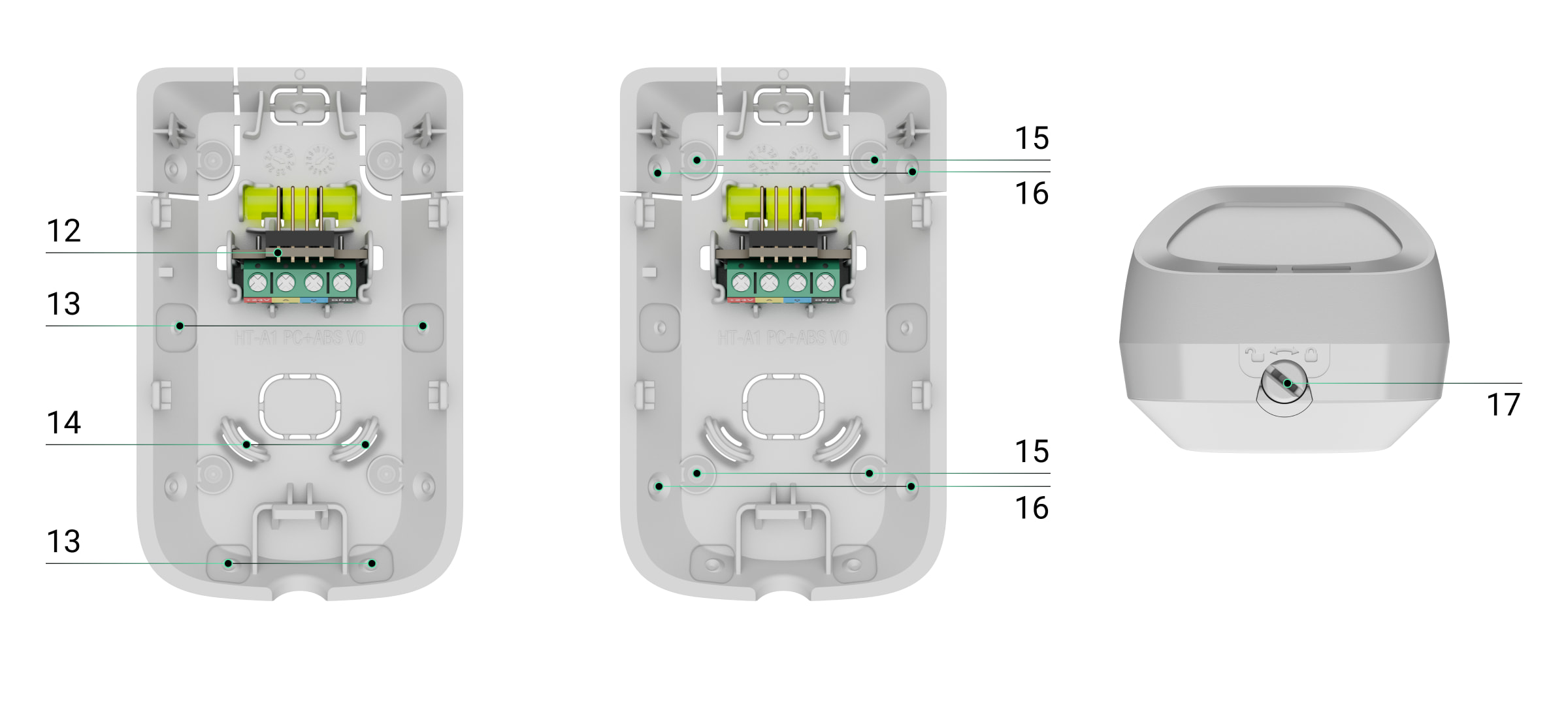
- Tamper buttons.
- Terminal strip connection socket.
- QR code with the device ID. It is used to add the device to the hub.
- Latch with a tamper button on the lock for SmartBracket.
- Terminal strip for the device connection.
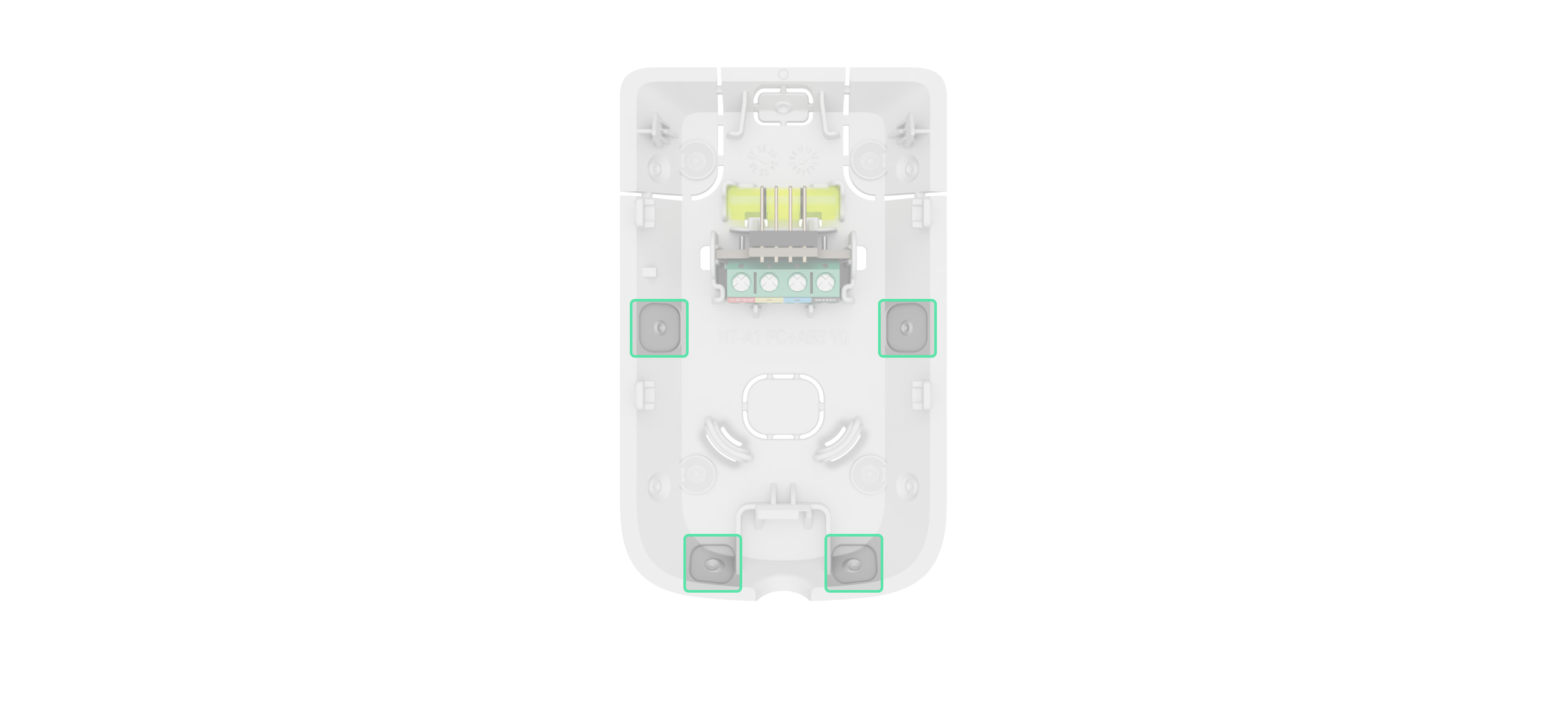
- Recesses for drilling holes to route cables from the sides or bottom of the device.
- Fasteners to fix the cables with ties.
- Spots for drilling holes to mount the device on the surface.
- Spots for drilling holes to mount the device on the corner.
- Lock for SmartBracket. It is used to fix the device on the SmartBracket mounting panel.
Operating principle
Superior MotionProtect Plus G3 Fibra is a wired IR motion detector with an additional K-band microwave sensor and anti-masking system. It can identify intrusions by detecting moving objects with temperatures close to the temperature of the human body.
When an armed detector identifies motion, it conducts an additional RF scan of the room with a built-in K-band microwave sensor to eliminate false alarms due to IR interference: air flows, heated curtains and blinds, fans, fireplaces, air conditioners, and other likely sources of false alarms.
In case of an alarm, it instantly sends an alarm to the hub, activating the sirens connected to the system, triggering scenarios, and notifying users and the security company. All Superior MotionProtect Plus G3 Fibra alarms and events are recorded in the event feed of the Ajax apps.
Users and the monitoring company know exactly where motion is detected. The notifications contain the name of a space (the name of a guarded facility), the device name, and the virtual room to which the device is assigned.
The detector does not switch to armed mode instantly. The switching time depends on the delay when leaving (specified in the device settings) and the hub–detector polling interval. The polling interval specified in the Jeweller/Fibra settings, by default its meaning is 36 seconds. In the first case, the delay is set by a user or a PRO with admin rights. In the second case, the delay occurs because the hub takes one polling interval to notify the detector about the security mode change.
Protection against false alarms
Superior MotionProtect Plus G3 Fibra uses the SmartDetect algorithm to protect against false alarms. This algorithm allows the detector to analyze the thermal diagram read by the sensor: the intensity of infrared radiation, size of the heat spot, time spent in the detection area, and other parameters.
After this stage, an additional RF scan of the room is run using the built-in K-band microwave sensor. Depending on the result, the alarm is activated or not.
Temperature compensation
Due to temperature compensation, the detector responds to movements, even if the temperature at the facility is close to the human body temperature. Read more about temperature compensation in the article.
Anti-masking system
Masking is an attempt to block the view of the detector. Superior MotionProtect Plus G3 Fibra detects the following types of masking:
- An obstacle in front of the detector’s motion sensor sensitive area.
- Painting over the detector’s motion sensor sensitive area.
- Taping the detector’s motion sensor sensitive area.
The system notifies users and the security company’s monitoring station about masking. The maximum masking detection time is up to 120 s (depending on the obstacle type and the distance to it).
If the Anti-masking feature is enabled, it is always active and works regardless of the security mode.
Fibra data transfer protocol
The device uses Fibra technology to transmit alarms and events and to update the firmware. It is a wired data transfer protocol for fast, reliable two-way communication between the hub and connected devices.
Firmware update
If a new firmware version for Superior MotionProtect Plus G3 Fibra is available, the ![]() icon appears in Ajax apps in the Devices
icon appears in Ajax apps in the Devices ![]() tab. An admin or a PRO with access to the system settings can run an update via device states or settings. The on-screen instructions help to update the firmware successfully.
tab. An admin or a PRO with access to the system settings can run an update via device states or settings. The on-screen instructions help to update the firmware successfully.
Sending events to the monitoring station
The Ajax system can transmit alarms to the PRO Desktop monitoring app as well as the central monitoring station (CMS) in the formats of SurGard (Contact ID), SIA (DC-09), ADEMCO 685, and other protocols.
Superior MotionProtect Plus G3 Fibra can transmit the following events:
- Motion alarm.
- Masking alarm.
- IR sensor malfunction/recovery.
- K-band microwave sensor malfunction/recovery.
- Masking sensor malfunction/recovery.
- Tamper alarm. Tamper recovery.
- Low supply voltage and voltage return to normal values.
- Loss and restoration of connection with the hub.
- Permanent deactivation/activation of the device.
- One-time deactivation/activation of the device.
When an alarm is received, the operator of the security company monitoring station knows what happened and precisely where to send a fast response team. The addressability of Ajax devices allows sending events to the PRO Desktop or the CMS, the type of the device, its name, security group, and virtual room. The list of transmitted parameters may differ depending on the type of CMS and the selected communication protocol.
You can find the device ID, loop (zone) number, and line number in the device States.
Selecting the installation site
When choosing where to place Superior MotionProtect Plus G3 Fibra, consider the parameters that affect its operation:
- Fibra signal strength.
- The length of the cable for connecting the detector.
- Detection zone.
- Distance between the detector and other detector with K-band microwave sensor should be 8 inches or more.
Consider the recommendations for placement when developing a project for the system of the facility. The Ajax system must be designed and installed by specialists. A list of recommended partners is available here.
Fibra signal strength
Fibra signal strength is the ratio of undelivered or corrupted data packages to those expected over a specific time. The icon ![]() in the Devices
in the Devices ![]() tab in Ajax apps indicates the signal strength:
tab in Ajax apps indicates the signal strength:
- Three bars — excellent signal strength.
- Two bars — good signal strength.
- One bar — low signal strength; stable operation is not guaranteed.
- Crossed out icon — no signal; stable operation is not guaranteed.
Lines power test
The test simulates the maximum energy consumption of devices connected to the hub. If the system passes the test successfully, all its devices have enough power in any situation. After the test, the app displays a notification with the status of each line:
- Test passed.
- Test passed with malfunctions.
- Test failed.
Motion detector detection area
The location of the detector determines the area to be monitored and the effectiveness of the security system. When selecting the installation place, consider the direction of the detector sensors, viewing angles, and the presence of obstacles to the detector’s view.
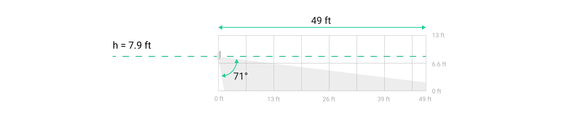
The detector can recognize motion at a distance of up to 49 ft. The direction of the detector sensors should be perpendicular to the intended entry path into the premises. Ensure that furniture, house plants, vases, and decorative or glass elements do not obstruct the view of the detector.
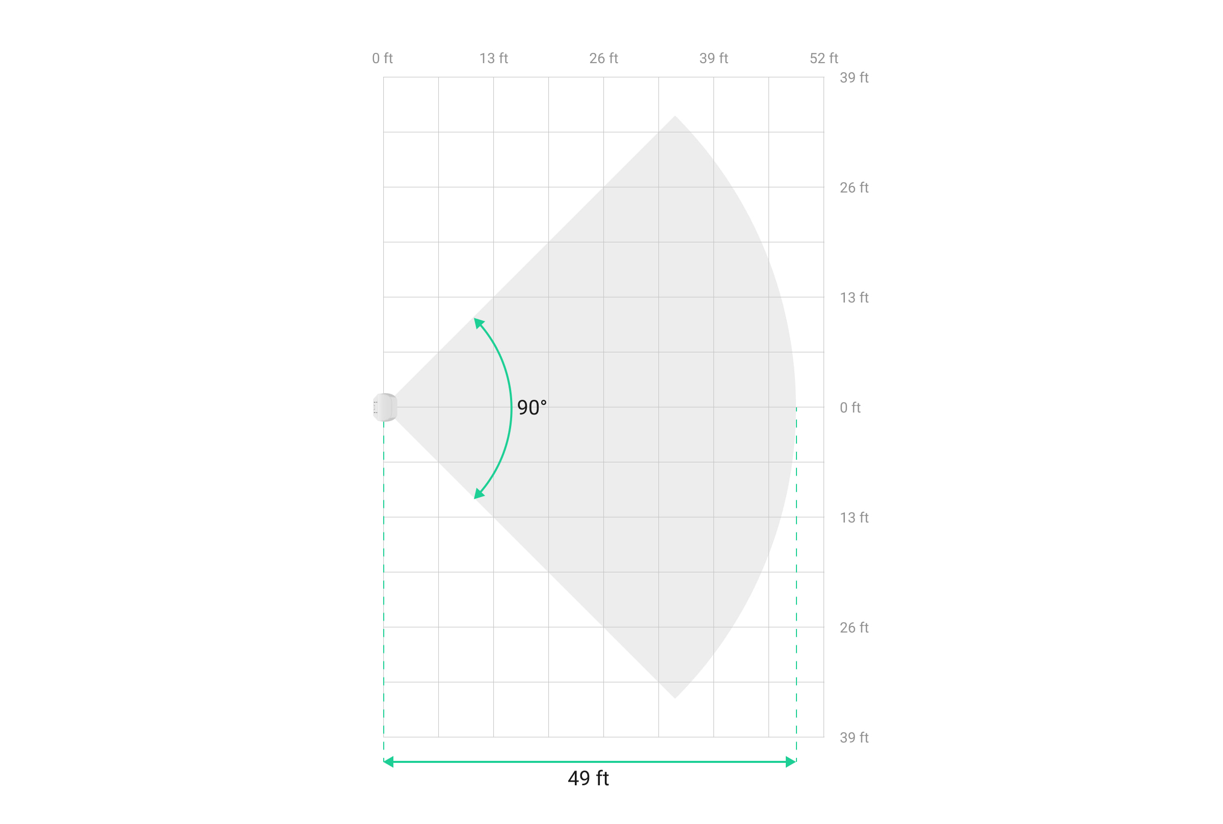
Horizontal characteristics of the motion detection area

Vertical characteristics of the motion detection area
When installing the detector, perform the Detection zone test. This allows you to check the operation of the device and accurately determine the sector in which the detector registers motion.
Do not install the detector
- Outdoors. This could damage the device.
- In places where objects and structures may obstruct the detector’s view. For example, behind a flower or a column.
- In places where glass structures may obstruct the detector’s view; it doesn’t register movement behind glass.
- Inside premises with temperature and humidity outside the permissible limits. This could damage the device.
- Near other detectors with K-band microwave sensors. The minimum distance between devices should be at least 8 inches. Otherwise, it can decrease detection quality or trigger false alarms due to wave interference of K-band microwave sensors.
- In places with low or unstable Fibra signal strength.
Designing and preparing
It is crucial to properly design the system project to install and configure the devices correctly. The project must consider the number and types of devices at the object, their exact location and installation height, the length of wired Fibra lines, the cable type, and other parameters.
Superior MotionProtect Plus G3 Fibra can be connected at any point of the Fibra line. Wired communication can be up to 6,550 ft long when connected using the U/UTP cat.5 twisted pair cable.
Ajax systems support Beam and Ring topologies.
Cable length and type
Recommended cable types for connecting Superior MotionProtect Plus G3 Fibra to the hub:
- U/UTP cat.5 4×2×0.51 mm (24 AWG) cable, copper conductor;
- 4×0.22 mm² signal cable, copper conductor.
The wired connection range may vary if you use a different cable type. No other types of cables have been tested.
Verification using a calculator
Use the Fibra power supply calculator to ensure that the project is designed correctly and the system will work in practice. It helps to check the communication quality and cable length for wired Fibra devices when designing the system project.
Preparing for installation
Cable arrangement
When preparing to lay cables, check the electrical and fire safety regulations in your region. Strictly follow these standards and regulations. Tips for cable arrangement are available in the article.
Cable routing
We recommend you carefully read the Selecting the installation site section before installation. Do not deviate from the system project. Violating the basic Superior MotionProtect Plus G3 Fibra installation rules and the recommendations of this manual may lead to incorrect operation and loss of connection with the device. Tips for cable routing are available in the article.
Preparing cables for connection
Remove the insulating layer and strip the cable with a special insulation stripper. The ends of the wires inserted into the device terminals must be tinned or crimped with a sleeve. It ensures a reliable connection and protects the conductor from oxidation. Tips for preparing the cables are available in the article.
Installation and connection
Before installing Superior MotionProtect Plus G3 Fibra, ensure that the optimal detector location has been selected and meets the requirements of this manual. Cables must be hidden from view and located in a difficult place for intruders to access to reduce the likelihood of sabotage. Ideally, mount them in the walls, floor, or ceiling. Before final installation, run the Detection zone test and Fibra signal strength test.
To mount a detector:
- Turn off the power of lines in the Ajax PRO app:
- Hub → Settings
 → Lines → Lines power supply
- Hub → Settings
- Route the cable to connect Superior MotionProtect Plus G3 Fibra to the hub casing. Connect the wires to the required hub line.
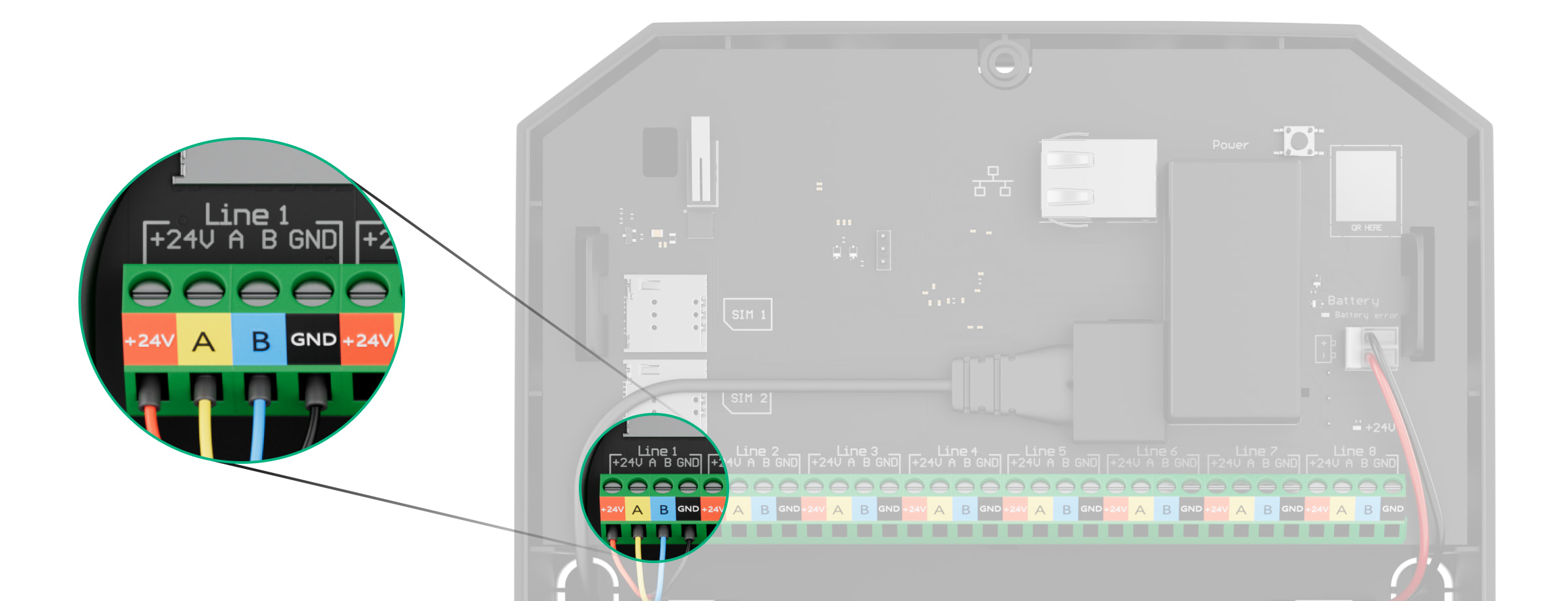
+24V — 24 V⎓ power terminal.
А, B — signal terminals.
GND — ground. - Remove the SmartBracket mounting panel from the detector. Carefully break out the corresponding perforated part to output the cable from the back or top.
If it is necessary to output cable from the bottom or the side, make holes carefully in the places indicated in the figure using a drill at low speed.
- Run the cable from the hub into the detector enclosure through the hole that was made.
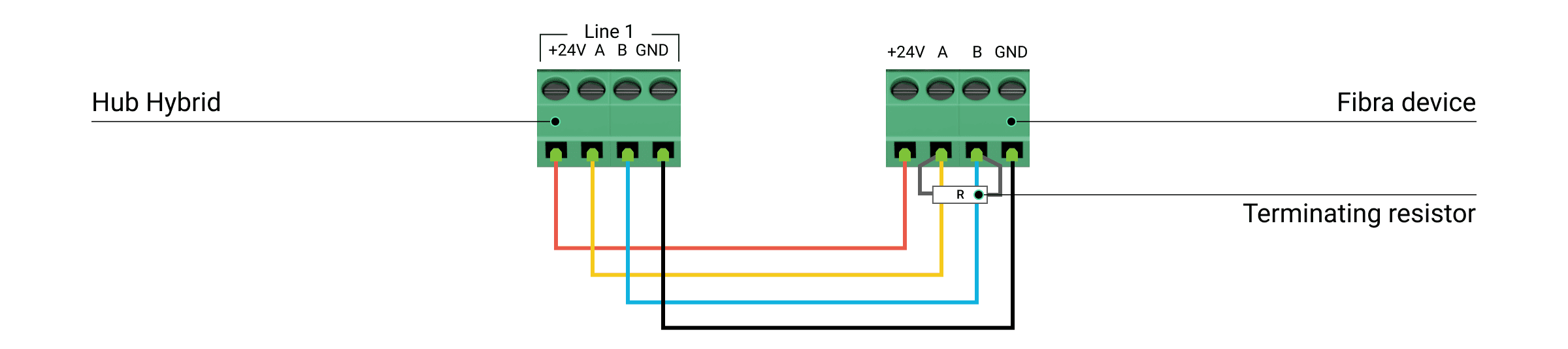
- Connect the wires to the terminals according to the figure below. Ensure the correct polarity and order of the wire connections. Firmly secure the cable to the terminals.
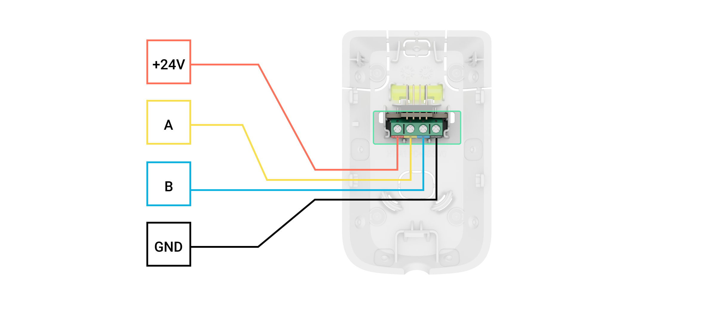
+24V — 24 V⎓ power terminal.
А, B — signal terminals.
GND — ground.- If the detector is not the last one in the connection line, prepare a second cable in advance. The ends of the wires of the first and second cables, which will be inserted into the detector terminals, must be tinned and soldered together or crimped with special tips.
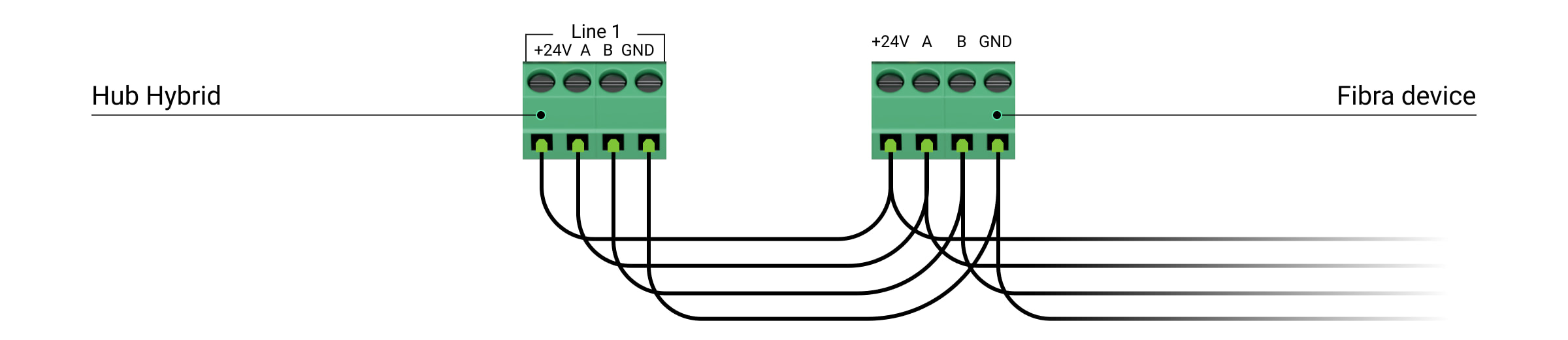
- If Superior MotionProtect Plus G3 Fibra is the last device on the line and you are using the Beam (Radial) connection, install a terminating resistor on the two contacts by connecting it to the signal terminals of the device. Terminating resistor (120 Ohm) is included in the hub complete set. When the Ring connection is used, a terminating resistor is not needed.

We recommend using the Ring connection method (hub–device–hub). If the ring is broken, not a single device will be disabled. In this case, two beams are formed, which will continue to operate normally and transmit events to the hub. If the ring is broken, the users and the security company receive a notification.
- If the detector is not the last one in the connection line, prepare a second cable in advance. The ends of the wires of the first and second cables, which will be inserted into the detector terminals, must be tinned and soldered together or crimped with special tips.
-
Temporarily secure the SmartBracket panel to a vertical surface or corner using double-sided adhesive tape or other temporary fasteners. This is necessary for testing the detector. The installation height is 7.9 ft.
- Place the detector on the SmartBracket mounting panel and lock it.
- Turn on the power supply of lines in the Ajax PRO app:
- Hub → Settings → Lines → Lines power supply
- Hub → Settings
- Add the detector to the system.
- Run the functionality testing.
- If the detector passes the tests, fix the SmartBracket mounting panel to a vertical surface with bundled screws. Use at least two fixing points (one is in the perforated part of the mount above the tamper). The tamper reacts if someone tries to break or open the lid of the enclosure — the notification about this is sent to Ajax apps.
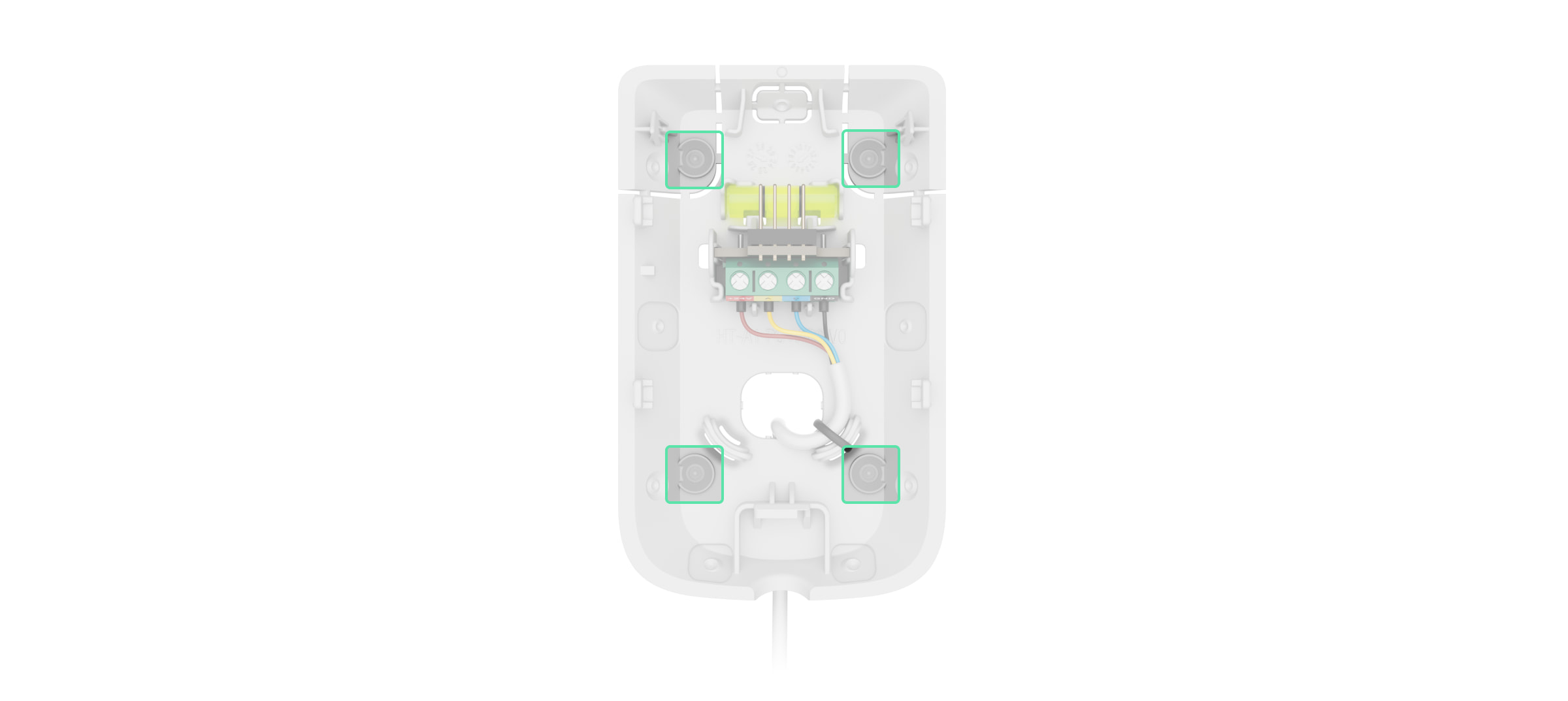
To fix SmartBracket on the corner, screw the bundled fasteners to the side recesses. Use at least two fixing points (one is in the perforated part of the mount above the tamper).
When using other mounts, make sure they do not damage or deform the mounting panel.

Double-sided adhesive tape can be used for temporary fastening as the device can come unglued from the surface at any time. As long as the device is taped, the tamper will not be triggered when the detector is detached from the surface.
- Put the detector on the SmartBracket mounting panel and lock it. The lock for SmartBracket has a tamper and is needed to securely fix the detector and protect it from quick dismantling. The tamper responds if someone tries to unlock the lock for SmartBracket, and the notification about this is sent to Ajax apps.
Adding to the system
Superior MotionProtect Plus G3 Fibra is compatible only with Superior Hub Hybrid (2G) and Superior Hub Hybrid (4G). Only verified partners can add and configure Superior devices in Ajax PRO apps.
Before adding a device
- Install an Ajax PRO app.
- Log in to a PRO account or create a new one.
- Select a space or create a new one.
- Add at least one virtual room.
- Add a compatible hub to the space. Ensure the hub is switched on and has internet access via Ethernet and/or mobile network.
- Ensure the space is disarmed, and the hub is not starting an update by checking statuses in the Ajax app.
Adding to the hub
Two ways to add devices are available in the Ajax PRO app: automatically and manually.
- Open the Ajax PRO app. Select the hub to which you want to add Superior MotionProtect Plus G3 Fibra.
- Go to the Devices
 tab and tap Add device.
 - Select Add all Fibra devices. The hub will scan the Fibra lines. After scanning, all devices connected to the hub that still need to be added to the system will be shown.
Scanning is also available in the Lines menu:
Hub → Settings
 → Lines → Add all Fibra devices.
 - Select the device from the list. After pressing, the LED indicator will flash to identify this device.
- Set the device name, and specify the room and security group if Group mode is enabled.
- Tap Save.
The detector connected to the hub will appear in the list of hub devices in the Ajax app.
Device status updating depends on the Fibra settings; the default value is 36 seconds.
If the connection fails, check the wired connection’s correctness and try again. If the maximum number of devices (100 for Superior Hub Hybrid) has already been added to the hub, you will receive an error notification while adding.
Superior MotionProtect Plus G3 Fibra only works with one hub. The detector stops exchanging data with the previous hub when pairing with a new one. When Superior MotionProtect Plus G3 Fibra is added to a new hub, it remains in the list of devices on the previous hub. You can remove it manually.
Functionality testing
The Ajax system offers several types of tests to help select the correct installation place for the devices. Available for Superior MotionProtect Plus G3 Fibra:
- Fibra signal strength test — to determine the strength and stability of the signal at the device installation site.
- Detection zone test — to check how the detector responds to motion and masking at the device installation site.
- Calibration of masking sensor — to register the detector’s field of view characteristics at the installation site. These characteristics will be used as a reference for masking detection.
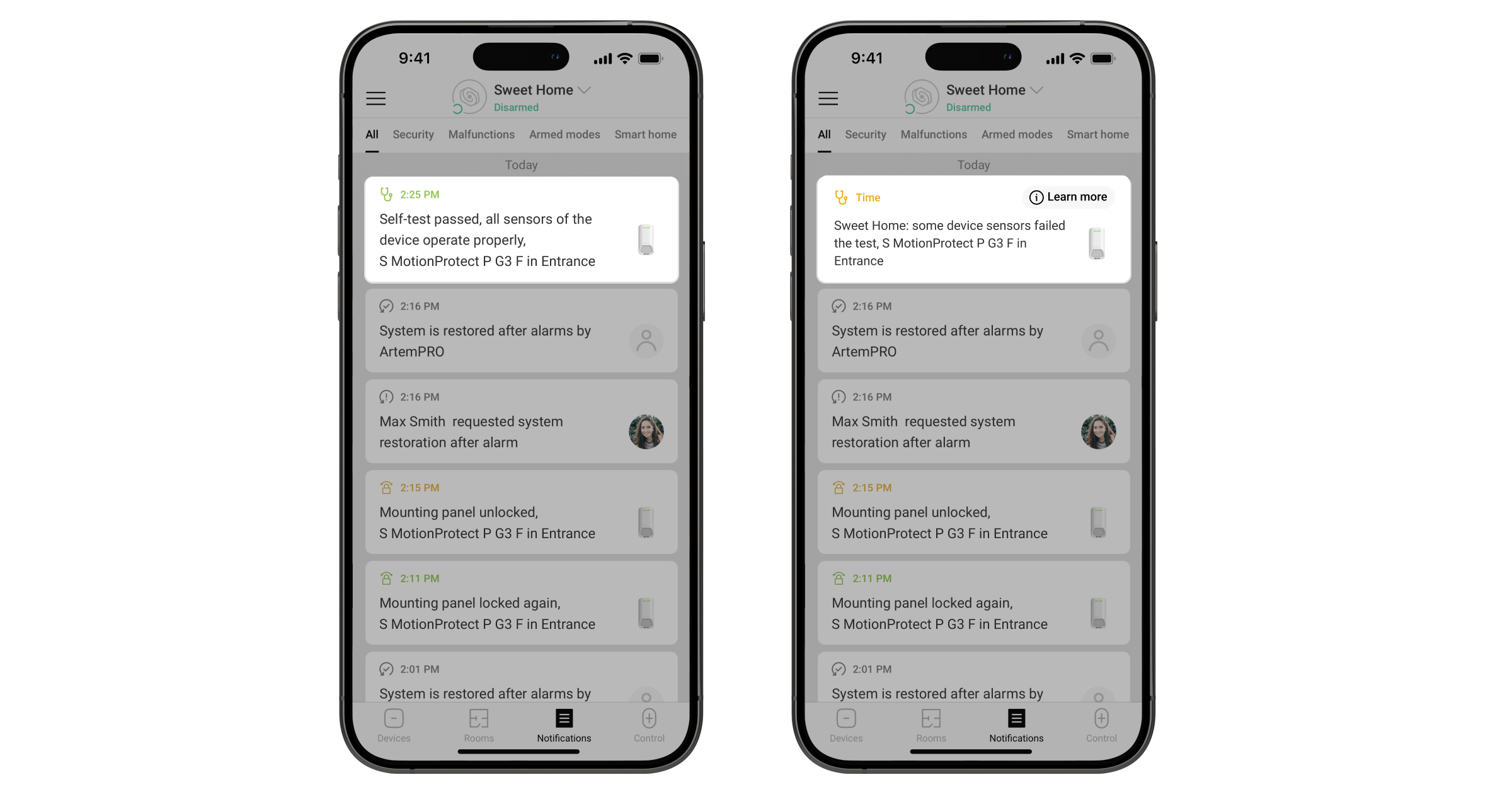
- Device self-test — to check if all detector’s built-in sensors operate properly.
Icons
Icons in the Ajax app display some of Superior MotionProtect Plus G3 Fibra states. Icons can be checked in the Devices ![]() tab.
tab.
| Icon | Meaning |
|
Fibra signal strength — displays the signal strength between the hub and the device. Recommended values: 2–3 bars. |
|
| A firmware update is available. Go to the device states or settings to find the description and launch an update. | |
|
The device operates in the Always active mode. |
|
| The lock for SmartBracket is unlocked. | |
|
Delay when entering and/or leaving enabled. |
|
|
The device operates in Night mode. |
|
| The masking is detected. | |
|
The device is automatically disabled due to exceeding the number of alarms. |
|
|
The device is permanently deactivated. |
|
|
Tamper alarm notifications are permanently deactivated. |
|
|
The device is deactivated until the first disarming of the system. |
|
|
Tamper alarm notifications are deactivated until the first disarming of the system. |
|
| The device has lost connection with the hub or the hub has lost connection with the Ajax Cloud server. | |
|
The device has not been transferred to the new hub. |
States
The states include information about the device and its operating parameters. The states of Superior MotionProtect Plus G3 Fibra can be found in Ajax apps:
- Go to the Devices tab.
- Select Superior MotionProtect Plus G3 Fibra in the list.
| Parameter | Meaning |
| Data import | Displays the error when transferring data to the new hub:
|
| Malfunction |
Tapping on The field is displayed only if a malfunction is detected. |
| New firmware version available |
Tapping on The field is displayed if a new firmware version is available. |
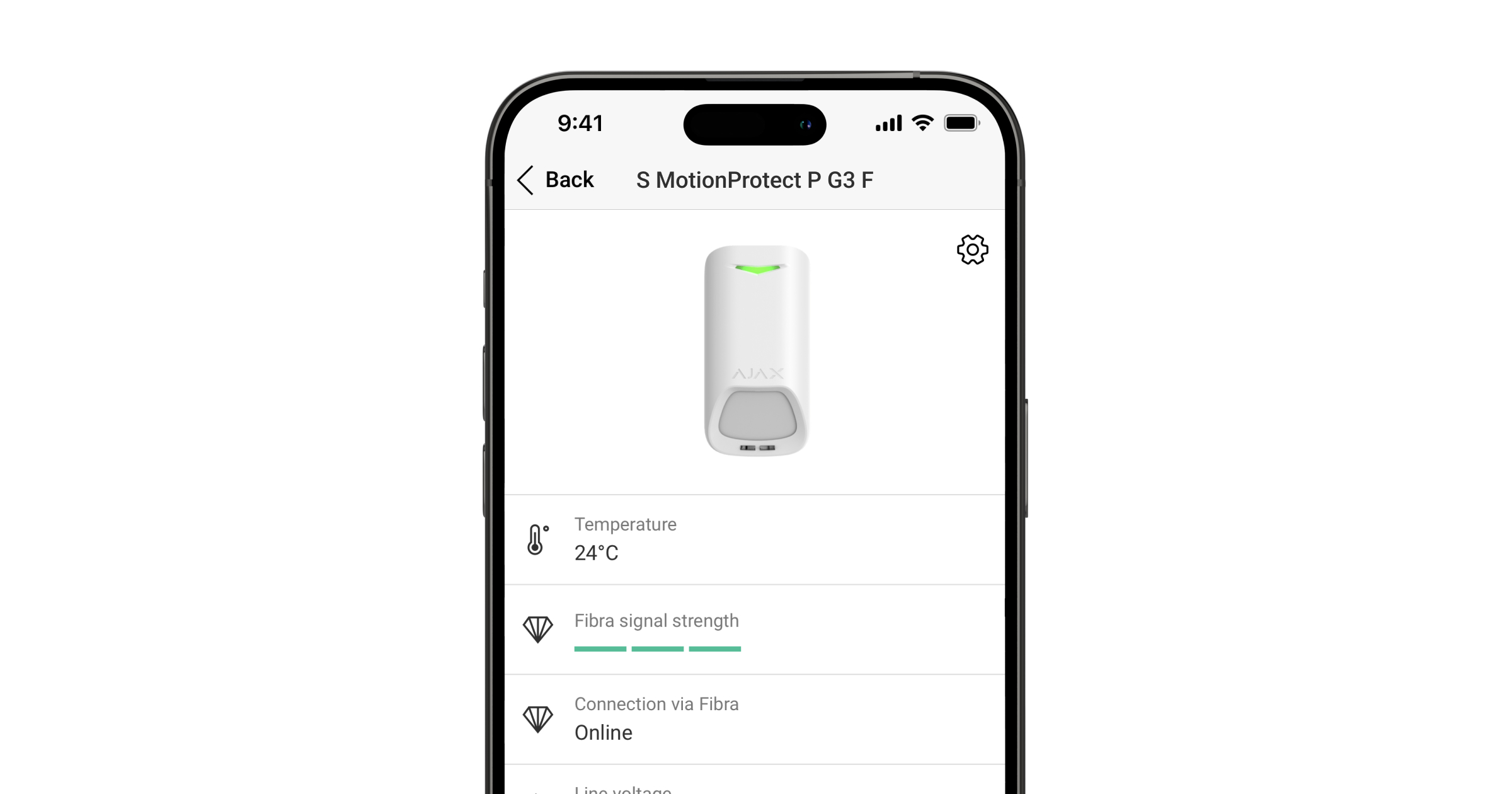
| Temperature |
Device temperature. The acceptable error between the value in the app and the temperature at the installation site: 4 °F. The value is updated as soon as the device detects a temperature change of at least 2 °F. You can create a scenario by temperature to control automation devices. |
| Fibra signal strength |
Signal strength between the hub and Superior MotionProtect Plus G3 Fibra. Recommended values: 2–3 bars. Fibra is a protocol for transmitting events and alarms. |
| Connection via Fibra | The status of the connection between the hub and the device:
|
| Line voltage | The voltage value on the Fibra line to which the device is connected. |
| Lid | The status of the device tampers that respond to detachment or opening of the device enclosure:
|
| Mounting panel | The status of the device tamper that responds to unlocking the SmartBracket mounting panel lock:
|
| Anti-masking | The status of the masking sensor:
|
| Always active |
When this option is enabled, the detector is constantly armed, detects motion, and raises alarms. |
| Permanent deactivation | The status of the device permanent deactivation setting:
|
| One-time deactivation | Shows the status of the device one-time deactivation setting:
|
| Alarm reaction | |
| Operating mode | Shows how the detector reacts to alarms:
|
| Delay when entering |
Delay when entering (alarm activation delay) is the time the user has to disarm the security system after entering the premises. |
| Delay when leaving |
Delay when leaving (arming delay) is the time the user has to leave the premises after arming. |
| Arm in Night mode |
When this option is enabled, the device will enter the armed mode when the system is set to Night mode. |
| Night mode delay when entering |
Entry delay time in Night mode. Delay when entering (alarm activation delay) is the time the user has to disarm the security system after entering the premises. |
| Night mode delay when leaving |
Leaving delay time in Night mode. Delay when leaving (arming delay) is the time the user has to leave the premises after enabling Night mode. |
| Night mode delay |
Entry delay time in Night mode when the device is set to the Follower operating mode. It is the time the user has to disable Night mode (alarm activation delay) after the Entry/Exit detector is triggered. |
| Firmware | Device firmware version. |
| Device ID | Device ID. Also available on the QR code on the device enclosure and its package box. |
| Device No. | Device number. This number is transmitted to the CMS in case of an alarm or event. |
| Line No. | The number of the hub’s Fibra line to which the device is connected. Displayed in case of Beam (Radial) connection. |
| Ring No. | The number of the hub’s Fibra ring to which the device is connected. Displayed in case of Ring connection. |
Settings
To change Superior MotionProtect Plus G3 Fibra settings in the Ajax apps:
- Go to the Devices tab.
- Select Superior MotionProtect Plus G3 Fibra in the list.
- Go to Settings .
- Set the required settings.
- Tap Back to save the new settings.
| Settings | Meaning |
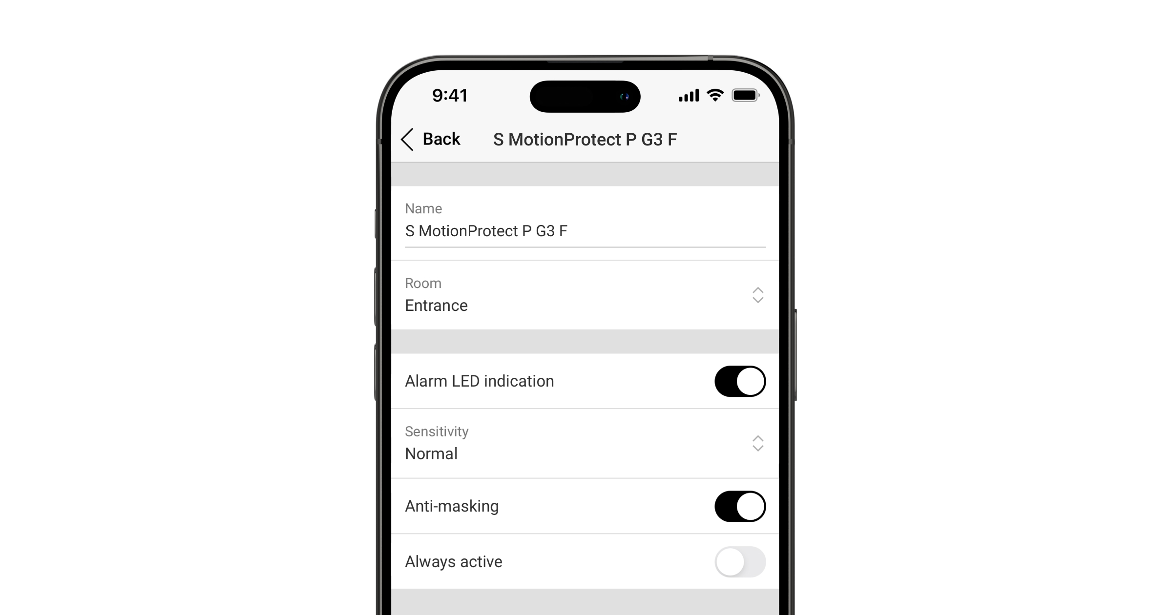
| Name |
Device name. Displayed in the list of hub devices, text of SMS and notifications in the events feed. To change the device name, tap on the text field. The name can contain up to 24 Latin characters or up to 12 Cyrillic characters. |
| Room |
Selecting the virtual room to which Superior MotionProtect Plus G3 Fibra is assigned. The room name is displayed in the text of SMS and notifications in the events feed. |
| Alarm LED indication | When disabled, the LED indicator doesn’t notify about alarms and tamper triggering. |
| Anti-masking | When this option is enabled, the device detects the masking. |
| Always active |
When enabled, the detector is always in the armed mode and detects motion. |
| Alert with a siren | |
| If motion detected | When enabled, sirens added to the system are activated when the device detects the motion. |
| If masking detected |
When enabled, sirens added to the system are activated when the device detects masking. The parameter is displayed if the Anti-masking option is enabled. |
| Alarm reaction | |
| Operating mode | Specify how this device will react to alarms:
|
| Delay when entering |
Selecting delay time when entering: 5 to 255 seconds. Delay when entering (alarm activation delay) is the time the user has to disarm the security system after entering the premises. |
| Delay when leaving |
Selecting delay time when leaving: 5 to 255 seconds. Delay when leaving (arming delay) is the time the user has to leave the premises after arming. |
| Arm in Night mode |
When enabled, the detector will enter the armed mode when the system is set to Night mode. |
| Night mode delay when entering |
Delay time when entering in Night mode: 5 to 255 seconds. Delay when entering (alarm activation delay) is the time the user has to disable Night mode after entering the premises. |
| Night mode delay when leaving |
Delay time when leaving in Night mode: 5 to 255 seconds. Delay when leaving (arming delay) is the time the user has to leave the premises after enabling Night mode. |
| Night mode delay |
Delay time in Night mode: 5 to 255 seconds. It is the time the user has to disable Night mode (alarm activation delay) after the Entry/Exit detector is triggered. The setting is displayed if the device is set to the Follower operating mode and the Arm in Night mode option is enabled. |
| Firmware update | Switches the device to the firmware updating mode if a new version is available. |
| Fibra signal strength test |
Switches the device to the Fibra signal strength test mode. The test allows you to check the signal strength between the hub and the device via the wired Fibra data transfer protocol to select the optimal installation site. |
| Detection zone test |
Switches the detector to the detection zone test mode. The option allows testing motion and masking sensors. The test helps to check whether the device is installed correctly to detect all alarms. |
| Calibration of masking sensor |
Runs the calibration of the masking sensor to ensure that the device operates correctly and can instantly detect attempts to block its field of view. |
| Device self-test |
Runs the device self-test to check if the built-in sensors operate properly. The test checks the IR motion sensor, K-band microwave sensor, and masking sensor. |
| User guide | Opens the Superior MotionProtect Plus G3 Fibra user manual in the Ajax app. |
| Permanent deactivation |
Allows the user to disable events of the device without removing it from the system. Three options are available:
The system can also automatically deactivate devices when the set number of alarms is exceeded. |
| One-time deactivation |
Allows the user to disable events of the device until the first disarm. Three options are available:
|
| Delete device | Unpairs the device, disconnects it from the hub, and deletes its settings. |
Calibration of masking sensor
Calibration of the masking sensor is important to ensure that the device operates correctly and can instantly detect attempts to block its sensors’ field of view. Calibration starts automatically when the device is added to the system. If the device fails to calibrate the masking sensor, the system sends a notification to users and the CMS and displays the corresponding fault in the device States.
You can start the calibration of the masking sensor manually, for example, if the automatic calibration fails or the device installation location has been changed.
Before starting the calibration, ensure the device is installed properly and nothing blocks its field of view.
To start calibrating the masking sensor, in the Ajax app:
- Go to the Devices tab.
- Select Superior MotionProtect Plus G3 Fibra from the list.
- Go to Settings .
- Go to the Calibration of masking sensor menu.
- Tap Start.
- If the calibration is successful, tap Close to return to the settings. If the device fails to calibrate the masking sensor, check if it is installed correctly and nothing blocks its field of view. Then tap Restart.
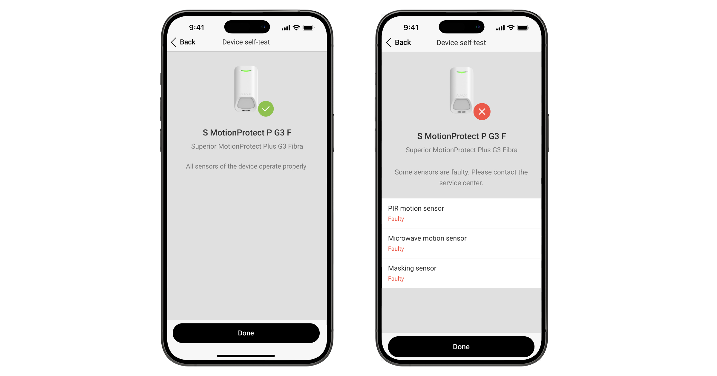
Device self-test
Device self-testing allows users to check if the device’s built-in sensors operate properly. During the self-test, the IR motion sensor, K-band microwave sensor, and masking sensor will be tested. The device runs the self-test of the built-in sensors automatically on a regular basis. If a malfunction is detected, the system notifies users and the CMS.
In addition, the device self-test procedure can be started manually in Ajax apps.
Before running the self-test, ensure that the system is disarmed, and another test is not in progress.
To run self-testing, in the Ajax app:
- Go to the Devices tab.
- Select Superior MotionProtect Plus G3 Fibra from the list.
- Go to Settings .
- Go to the Device self-test menu.
- Tap Start.
- If self-testing is successful, tap Done to return to the settings. If some sensors are faulty, we recommend contacting the service center.
Note that on hubs with OS Malevich 2.36 and later, the device self-test checks only the enabled sensors of the device.
If a faulty sensor is disabled, the system will not show the malfunction counter in an Ajax app and will not notify users about the sensor malfunction. However, if a user enables a faulty sensor, the system will send a notification that the sensor is malfunctioning.
Users and the CMS will receive a corresponding notification about the testing result after completion.
Indication
The Superior MotionProtect Plus G3 Fibra LED indicator may light up green or red, depending on the status of the device.
| Indication | Event | Note |
| Lights up green for 0.3 seconds and goes out for 0.3 seconds three times. | The device detects an alarm when it is not added to the hub. | |
| Lights up green for 0.3 seconds and goes out for 0.3 seconds six times. | The device is deleted from the hub. | |
| Flashes green rapidly. | The device is selected from the list of devices found by scanning the Fibra lines to add to the hub. | |
| Lights up green for about 0.6 seconds. |
|
|
| Lights up green constantly and goes out for 0.6 seconds when motion is detected. | The detection zone test of the motion sensor is running for the device. | Learn more |
| Lights up red constantly and goes out completely when masking is detected. When the masking is removed, lights up red again. | The detection zone test of the masking sensor is running for the device. | Learn more |
| Lights up green for 0.5 seconds and goes out for 0.5 seconds. | Calibration of the masking sensor is in progress. | Learn more |
| Lights up red for about 1 second every 4 seconds. | The device hardware error or its sensors malfunction. | The device requires maintenance; contact our Technical Support. |
| Lights up red for about 1 second every 13 seconds. | Calibration of the masking sensor has failed. |
Ensure the device is installed properly and nothing blocks its field of view, and then restart the calibration. If the indication repeats, contact our Technical Support. |
Malfunctions
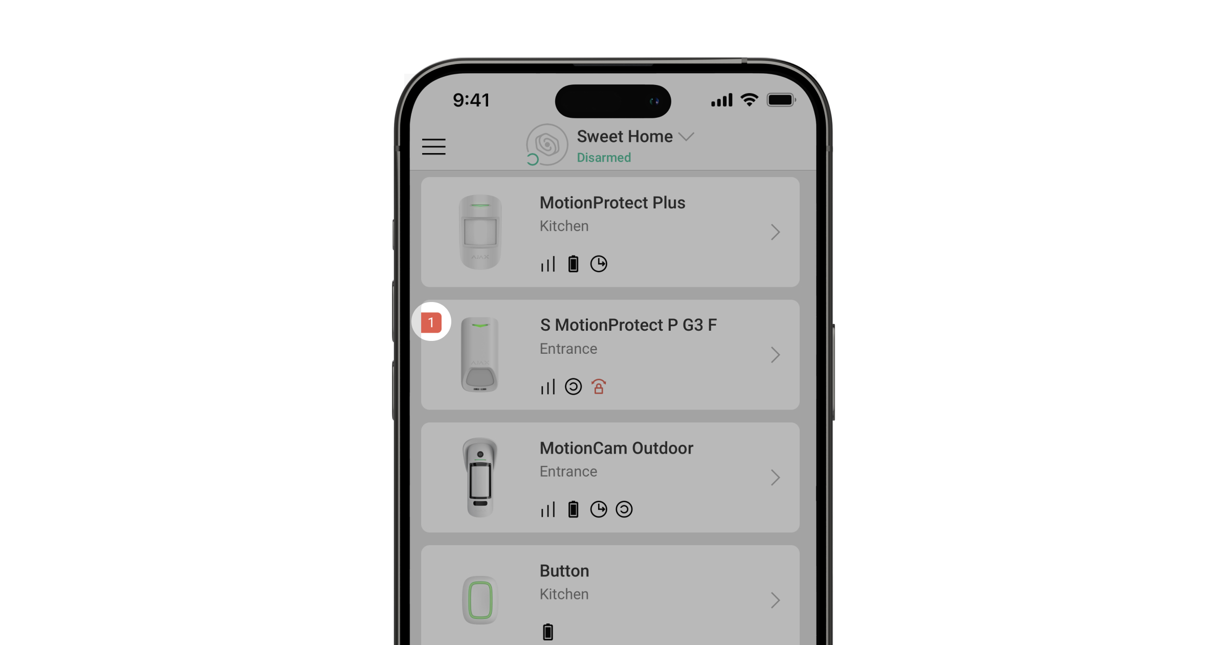
When the device detects a malfunction (for example, there is no connection via the Fibra protocol), a malfunction counter is displayed in the Ajax app in the upper left corner of the device icon.
All malfunctions can be seen in the device states. Fields with malfunctions will be highlighted in red.
Malfunction is displayed if:
- The device temperature is outside acceptable limits.
- The device mounting panel lock is unlocked (tamper is triggered).
- The device lid is open (tamper is triggered).
- There is no signal via Fibra protocol.
- The IR sensor is faulty.
- The K-band microwave sensor is faulty.
- The masking sensor is faulty.
- The calibration of the masking sensor has failed.
Maintenance
Regularly check the functioning of the device. The optimal frequency of checks is once every three months. Clean the device enclosure from dust, cobwebs, and other contaminants as they emerge. Use soft, dry wipes suitable for equipment maintenance.
Do not use substances that contain alcohol, acetone, gasoline, and other active solvents to clean the device.
Technical specifications
Warranty
The warranty for the products of the Limited Liability Company “Ajax Systems Manufacturing” is valid for 2 years after purchase.
If the device does not operate properly, we recommend contacting support service first, as most technical issues can be resolved remotely.
Contact Technical Support:
Manufactured by “AS Manufacturing” LLC
