Superior MultiTransmitter Fibra is an integration module designed to connect third-party wired devices to an Ajax system. It features 18 zones for connecting NC, NO, EOL, 2EOL, and 3EOL devices. The integration module is available in two versions: either in default casing or as a board without casing. The latter is called Superior MultiTransmitter Fibra (without casing) and can be installed into Case D (430).
Superior MultiTransmitter Fibra is equipped with two tampers for protection against dismantling. The device is powered from the 100–240 V~ mains, and can also be powered from the 12 V⎓ backup battery. It can supply 10.5–15 V⎓ power to connected devices.
Check the device compatibility before adding to the system.
Superior MultiTransmitter Fibra works as part of an Ajax system, exchanging data with the hub using the secure Fibra wired protocol. The wired connection range is up to 2,000 meters when using a U/UTP cat.5 twisted pair.
This is a device of the Superior product line. Only accredited Ajax Systems partners can sell, install and administer Superior products.
Functional elements
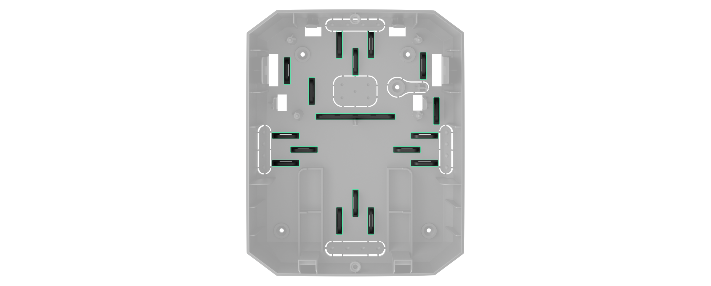
Casing elements
- Screws securing the casing lid. Unscrew with a bundled hexagon key (Ø 4 mm).
- Light guides for the integration module status indication (available in the new casing version, while the previous version features the LED indicator on the board).
- Space for a 12 V⎓ backup battery.

Backup battery is not included in the Superior MultiTransmitter Fibra complete set.
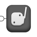
- Superior MultiTransmitter Fibra QR code and ID (serial number). It is used to pair the device with the Ajax system.
- Perforated part of the casing. Necessary for tamper triggering in case of any attempt to detach the device from the surface. Do not break it off.
- Perforated parts of the casing for cable output.
- Fasteners for securing cables.
Board elements
- Fire detectors power supply terminals 10.5–15 V⎓, up to 0.4 A.
- Superior MultiTransmitter Fibra 100–240 V~ main power supply input.
- First tamper button. Signals when trying to remove the lid of the Superior MultiTransmitter Fibra casing.
- Terminals for connecting a 12 V⎓ backup battery.
- Power button.
- LED indicator.
- Superior MultiTransmitter Fibra QR code and ID (serial number). It is used to pair the device with an Ajax system.
- Terminals (zones) for connecting wired detectors.
- Terminals for connecting Superior MultiTransmitter Fibra to the hub.
- Second tamper button. Signals when trying to tear off the Superior MultiTransmitter Fibra casing from the surface.
Superior MultiTransmitter Fibra terminals
Terminals for connecting Superior MultiTransmitter Fibra to the hub:
+24 V — 24 V⎓ power supply terminal.
А, B — signal terminals.
GND — power ground terminal.
Terminals for connecting wired devices to Superior MultiTransmitter Fibra:
Z1–Z18 — inputs for connecting wired devices.
+12 V — power supply output for wired devices, voltage 10.5–15 V⎓, up to 1 A in total for all power supply outputs.
+12V2 — power supply output for fire detectors, voltage 10.5–15 V⎓, up to 0.4 A in total for all power supply outputs.
COM — common input for connecting power supply circuits and signal contacts of wired devices.
Operating principle
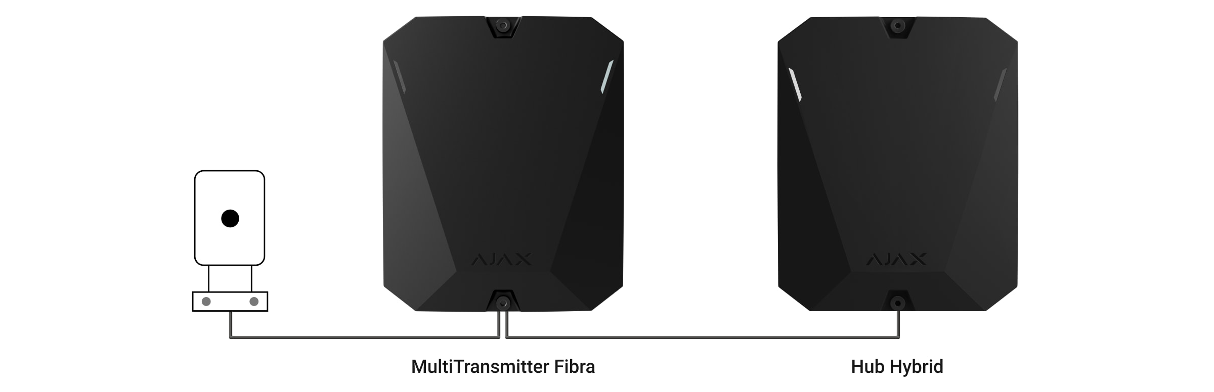
Superior MultiTransmitter Fibra is designed to integrate third-party wired devices into an Ajax system. The integration module receives information about alarms, malfunctions, and events from devices through a wired connection. After that, it sends the event to Superior Hub Hybrid using the Fibra data transfer wired protocol. And Superior Hub Hybrid sends messages to users and the security company CMS (central monitoring station).
Superior MultiTransmitter Fibra is used to integrate alarm and auxiliary request alert buttons, indoor and outdoor motion detectors. As well as detectors that track opening, vibration, glass breaking, fire, gas and water leakage, etc.
Also, you can set up KeyArm Zone that allows switching system arming modes with a third-party device connected to Superior MultiTransmitter Fibra. KeyArm allows you to arm/disarm the system, individual groups, or manage Night Mode.
The KeyArm feature is supported by all hubs (except Hub model) with OS Malevich 2.17 and higher.
The device type is specified in the settings of the zone to which the wired detector or device is connected. The selected type determines the text of alarm messages and events of the connected device, as well as event codes transmitted to the CMS.
The wired device connected to Superior MultiTransmitter Fibra can operate in one of the following sensor modes:
- Detect alarms
- Switch arming modes
- Control of blocking element
- Control of bolt lock
Types of wired devices
| Detect alarms operating mode | |||
| Event type | Icon | Meaning | |
| Tamper alarm |
 |
Event of a detector or device tamper triggering. | |
| Intrusion |
 |
Alarm when motion, opening, and other detectors are triggered. | |
| Fire |
 |
Alarm when fire detectors are triggered. | |
| Auxiliary alarm |
 |
Alarm when pressing the call button for assistance. | |
| Panic button |
 |
Alarm when the panic button is pressed. | |
| Gas alarm |
 |
Alarm when gas concentration is exceeded. | |
| Malfunction |
 |
An event caused by a malfunction of a connected detector or device. | |
| Leakage |
 |
Alarm caused by flooding. | |
| Glass break |
 |
Alarm when the glass break sensor is triggered. This event type operates only in Pulse operating mode. |
|
| High temperature |
 |
Alarm when the upper temperature limit is exceeded. | |
| Low temperature |
 |
Alarm when the lower temperature limit is exceeded. | |
| Masking |
 |
Alarm when the device masking is detected. | |
| Duress code (opening) |
 |
Alarm when the duress code is entered. This event type operates only in Pulse operating mode. |
|
| Vibration (seismic sensor) |
 |
Alarm when the seismic sensor is triggered. This event type operates only in Pulse operating mode. |
|
| Custom |
 |
The event type is customized by the user. Not sent to the security company monitoring station and users via SMS. |
|
| Switch arming modes | |||
| Icon | Meaning | ||
 |
You can set up KeyArm Zone that allows switching system arming modes with a third-party device connected to Superior MultiTransmitter Fibra. KeyArm allows you to arm/disarm the system, individual groups, or manage Night Mode.
The KeyArm feature is supported by compatible hubs with OS Malevich 2.17 and later. If the Followed group feature is configured for groups, their security state can automatically change depending on their settings and initiators’ states. . |
||
| Control of blocking element | |||
| Icon | Meaning | ||
 |
You can set up Control of blocking element that allows receiving notification on the status of third-party blocking element.
The Control of blocking element feature is supported by compatible hubs with OS Malevich 2.25 and later.This feature is part of the inevitability principle (German: Zwangsläufigkeit) flow. |
||
| Control of bolt lock | |||
| Icon | Meaning | ||
 |
You can set up Control of bolt lock that allows receiving notifications about the status of the lock bolt.
The Control of bolt lock feature is supported by compatible hubs with OS Malevich 2.25 and later.This feature is part of the inevitability principle (German: Zwangsläufigkeit) flow. |
||
Wired devices connection types
- NO (normally open).
- NC (normally closed).
- EOL (connection with one resistor).
- 2EOL (connection with two resistors).
- 3EOL (connection with three resistors).
In the Ajax app, you can select the normal state (normally open or normally closed) for each of the terminal pairs: alarm, tamper, and malfunction terminals. This allows connecting any potential-free (“dry”) contact detector of any configuration to Superior MultiTransmitter Fibra.
Fibra communication protocol
The integration module uses Fibra technology to transmit alarms and events. This is a two-way wired data transfer protocol that provides fast and reliable communication between the hub and integration module. Using the bus connection method, Fibra delivers alarms and events instantly, even if 100 devices are connected to the system.
Fibra supports block encryption with dynamic key and verifies each communication session with devices to prevent sabotage and spoofing. The protocol provides for regular polling of devices by the hub at a specified frequency to control communication and display the state of system devices in Ajax apps.
Sending events to the Central Monitoring Station (CMS)
An Ajax system can transmit alarms to the PRO Desktop monitoring app as well as the Central Monitoring Station (CMS) using SurGard (Contact ID), SIA DC-09 (ADM-CID), ADEMCO 685, and other proprietary protocols.
Superior MultiTransmitter Fibra can transmit the following events:
- Superior MultiTransmitter Fibra tampers alarm/restoration.
- Connected devices alarm/restoration.
- Loss/recovery of communication between Superior MultiTransmitter Fibra and hub.
- Disabling/enabling Superior MultiTransmitter Fibra.
- Disabling/enabling wired detectors and devices connected to Superior MultiTransmitter Fibra.
- Unsuccessful attempt to arm the system (if system integrity check is enabled).
When an alarm is received, the monitoring station operator of the security company knows what happened and where the rapid response unit has to be sent. All Ajax devices are addressable, so events, the device type, its assigned name and room can be transmitted to PRO Desktop and the CMS. The list of transmitted parameters may differ depending on the type of the CMS and the selected communication protocol.
The ID and number of the loop (zone) of the integration module and connected devices can be found in their States in Ajax apps. To check the loop (zone) number, open the States of the integration module or the connected wired device. The device number corresponds to the loop (zone) number.
Device placement
Superior MultiTransmitter Fibra integration module is mounted on a vertical surface with the bundled screws. All the necessary holes for fastening in the casing have already been made. Superior MultiTransmitter Fibra is designed for indoor installation only.
Vertical fixation of the integration module is needed for the tamper to respond if someone tries to detach a device. Learn the battery documentation before installing — some batteries can be mounted only vertically (with terminals upward). Another installation position could cause fast battery degradation.
It is advisable to choose an installation site where the hub is hidden from prying eyes — for example, in the storage room. This helps to reduce the risk of sabotage of the integration module and devices connected to it.
Selecting the installation site for Superior MultiTransmitter Fibra, take into account the parameters that affect the operation of the device module:
- Fibra signal strength.
- Cable length for connecting Superior MultiTransmitter Fibra.
- Cable length for connecting wired devices to Superior MultiTransmitter Fibra.
Consider the placement recommendations when designing the security system project for your object. The security system should be designed and installed by professionals. The list of authorized Ajax partners is available here.
Do not install Superior MultiTransmitter Fibra
- Outdoors. This can lead to the failure of the integration module.
- Inside premises where temperature and humidity levels exceed the permissible limits, as this can damage the integration module.
- In places with low or unstable Fibra signal strength, since this might cause a loss of connection with the hub.
Fibra signal strength
The Fibra signal strength is determined by the number of undelivered or corrupted data packages over a certain period of time. The icon ![]() in the Devices
in the Devices ![]() tab indicates the signal strength:
tab indicates the signal strength:
- Three bars: excellent signal strength.
- Two bars: good signal strength.
- One bar: low signal strength, stable operation is not guaranteed.
- Crossed out icon: no signal, stable operation is not guaranteed.
The following factors affect the signal strength:
- The number of devices connected to one Fibra line.
- Cable length and type.
- The correctness of the wire connections to the terminals.
Designing
It is crucial to design the system project properly to ensure the correct installation and configuration of the devices. The design must consider the number and types of devices at the object, their exact locations and installation heights, the length of wired Fibra lines and cables from other devices, the type of cable used, and other parameters. Refer to the article to learn tips for designing the Fibra system project.
Topologies
Fibra is a data transfer protocol for the Ajax wired devices. At the physical level, Fibra resembles a bus connection: the detectors are connected to the control panel using a four-core cable. Currently, Ajax systems support three topologies — Beam (Radial wiring), Ring, and Tree. Learn more about topologies in this article.
Cable length and type
For Superior MultiTransmitter Fibra
The maximum range of a wired connection using the Beam (Radial) topology is 2,000 meters, and using the Ring topology — 500 meters.
Recommended cable types:
- U/UTP cat.5, 4 × 2 × 0.51 mm (24 AWG), copper conductor.
- Signal cable 4 × 0.22 mm², copper conductor.
If you use a different type of cable, the communication range for wired connections may vary. No other types of cables have been tested.
For wired devices of third-party manufacturers
The maximum cable length for connecting third-party devices to Superior MultiTransmitter Fibra is 400 meters.
Recommended cable types:
- Signal cable 4 × 0.22 mm², copper conductor.
- Signal cable 4 × 0.22 mm², conductor material is aluminum covered with copper.
If you use a different type of cable, the communication range for wired connections may vary. No other types of cables have been tested.
Verification using a calculator
To ensure that the project is designed correctly and the system functions as intended in practice, we have developed a Fibra power supply calculator. It helps to check the communication quality and cable length for wired Fibra devices when designing the system project.
Additional information
The maximum current that Superior Hub Hybrid can supply in total for all Fibra lines is 600 mA. Please note that the total current consumption of the devices in the system depends on the type of cable, its length, the type of connected device, the quality of the connection of conductors, and other factors. Therefore, after selecting devices, we recommend verifying the project using the Fibra power supply calculator.
Up to 100 devices can be connected to Superior Hub Hybrid at default settings. Each device connected to Superior MultiTransmitter Fibra also occupies one slot within the device limit of the hub.
Superior MultiTransmitter Fibra supports EOL resistors with resistance from 1 to 15 kOhm. The total resistance of all resistors is up to 30 kOhm. To increase anti-sabotage protection, use EOL resistors with different resistances in one detector. The recommended resistance ratio of EOL resistors: R1=R, R2=2·R, R3=3·R.
The integration module has four 10.5-15 V⎓ power supply lines: one for the fire detectors and three — for other devices.
After an alarm, fire detectors require a power reset to restore the normal operation mode. Therefore, the fire detectors power supply should only be connected to a dedicated line. Also, avoid connecting other detectors and devices to power terminals of fire detectors as this may lead to false alarms or incorrect operation of the devices.
Preparing for installation
Cable arrangement
Before laying cables, check the electrical and fire safety regulations applicable in your region. Strictly follow these standards and regulations. Tips for cable arrangement are available in this article.
Cable routing
Before beginning the installation, we strongly advise reviewing the Device placement section thoroughly. Stick to the outlined system project without deviation. Violation of the basic Superior MultiTransmitter Fibra installation rules and the recommendations of this manual may lead to incorrect operation, as well as loss of connection with the device.
Signal cables of Fibra devices must be laid at a distance of at least 50 cm from the power cables when lying parallel, and, if they intersect, it must be at a 90° angle. Observe the permissible bend radius of the cable. It is specified by the manufacturer in the cable specifications. Otherwise, you risk damaging or breaking the conductor. Tips for cable routing are available in this article.
Preparing cables for connection
First, remove the insulation layer and strip the cable with a special insulation stripper. The ends of the wires inserted into the device terminals must be tinned or crimped with a sleeve. It ensures a reliable connection and protects the conductor from oxidation. Tips for preparing the cables are available in this article.
Features of enclosures of third-party wired devices may exclude the use of insulated ferrules. To connect such devices, you can use a wire-end ferrule without insulation with a cross-section of 0.5 mm² or more.
Installation
Before installing Superior MultiTransmitter Fibra, make sure that you have selected the optimal location and that it meets the requirements of this manual. To reduce the risk of sabotage, the cables must be hidden from view and located in a difficult place for intruders to access. Ideally, the cables should be mounted in walls, floors, or ceilings. Run the Fibra signal strength test before final installation.
When connecting to the terminals of the device, do not twist the wires together, but solder them. The ends of the wires that will be inserted into the terminals should be tinned or crimped with a special sleeve. This will ensure a reliable connection. Observe the safety procedures and the rules for electrical installation work when connecting the integration module and third-party devices.
Connecting to the hub
- Remove the Superior MultiTransmitter Fibra casing lid by unscrewing the bottom and top screws with the bundled hex wrench.
- Remove the Superior MultiTransmitter Fibra board from the holders by pulling them to the sides.
- Prepare cable openings in advance by carefully breaking out the perforated parts of the casing.

- Fasten the casing to a vertical surface at the chosen installation location using the bundled screws. When attaching, use all fixing points on the casing. One of them is in the perforated part above the tamper — it is required for tamper triggering in case of any attempt to detach Superior MultiTransmitter Fibra casing.
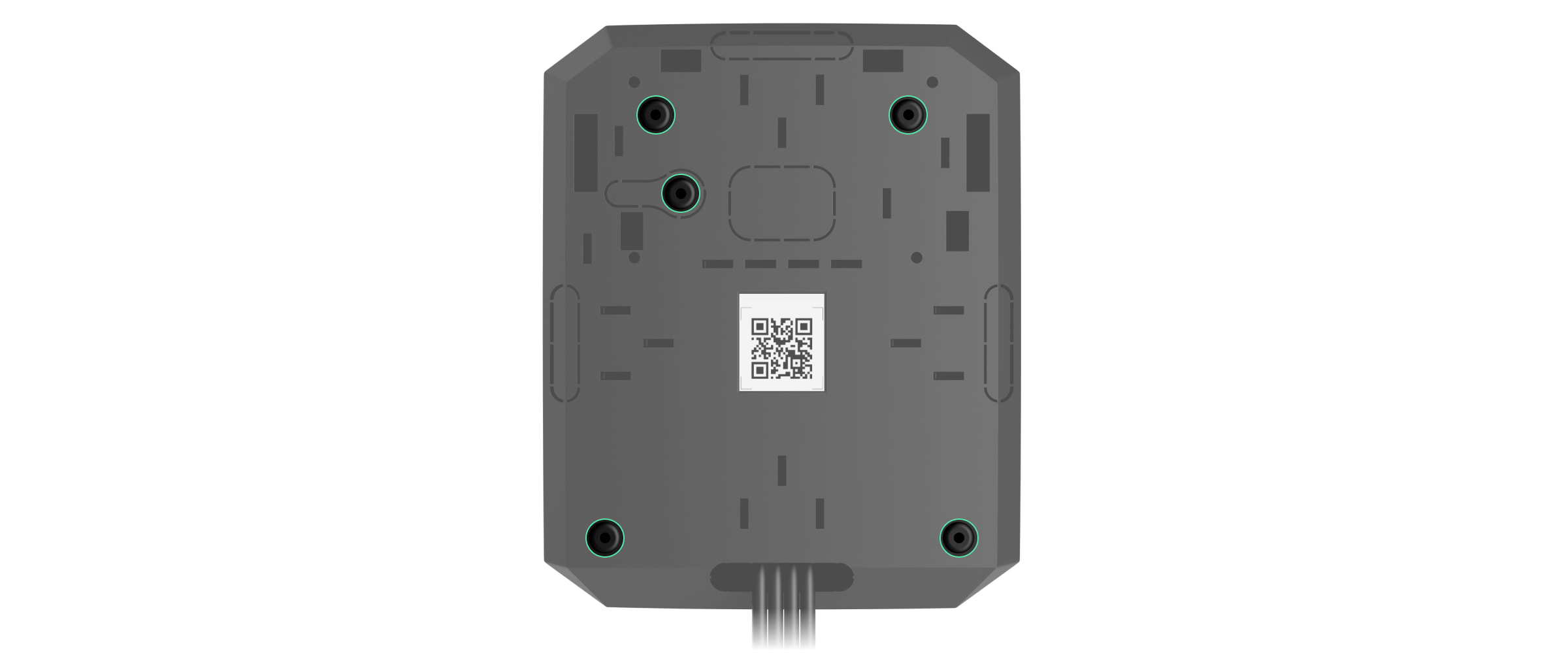
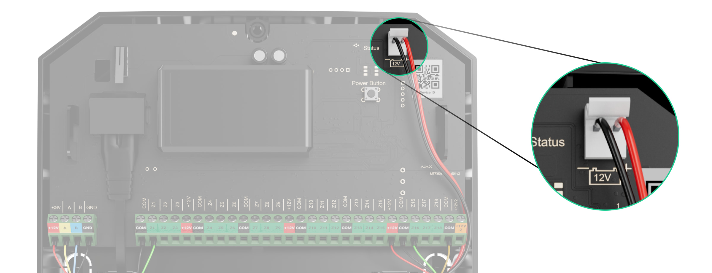
- Disconnect the external power and the hub backup battery.
1 — Backup battery.
2 — External power.To comply with the INCERT requirements, use the Screw terminal block Adapter to connect the external power supply. Read more.
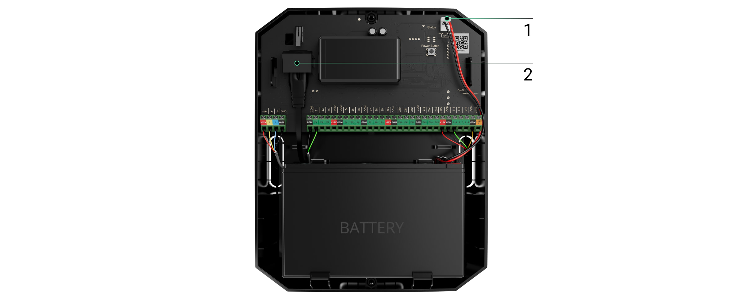
- Pull the cable into the hub. Connect the wires to the hub line.
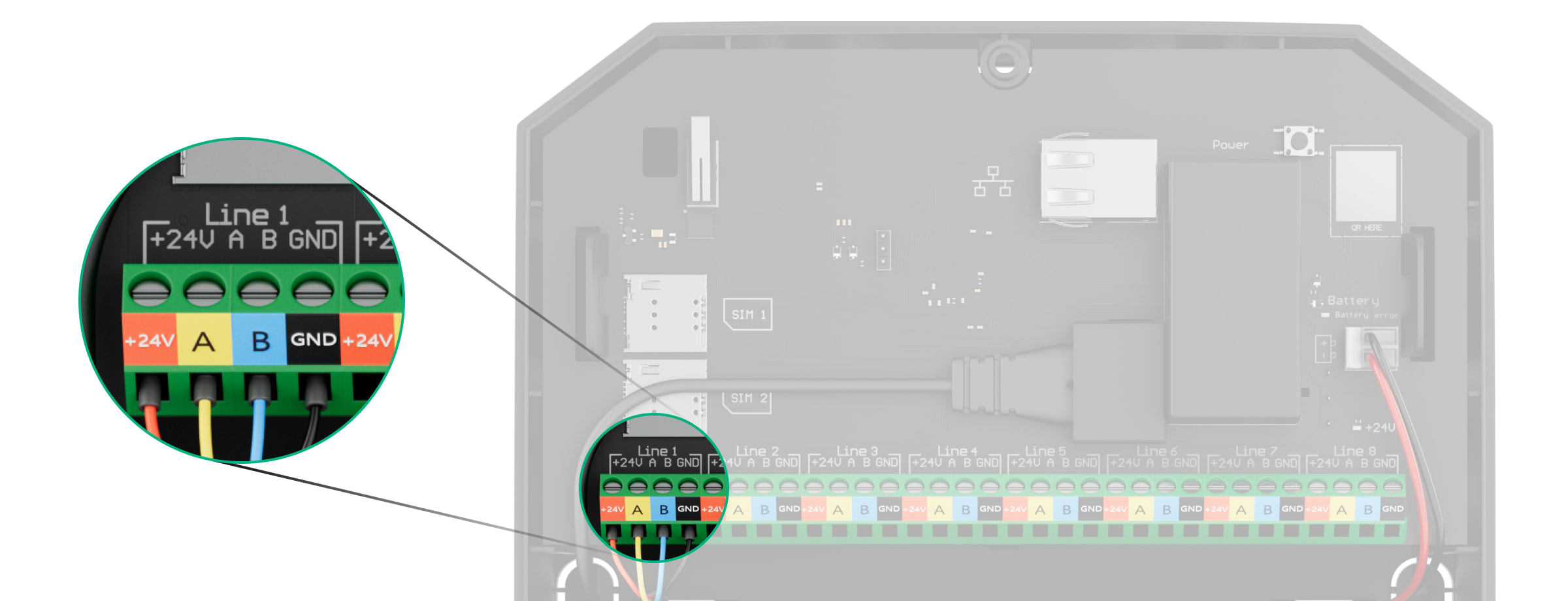
+24V — power supply terminal of 24 V⎓.
А, B — signal terminals.
GND — power ground terminal. - Pull the cable from the hub into the casing of the integration module through the holes made.
- Install the Superior MultiTransmitter Fibra board into the casing on special holders.
- If the integration module is not the last in the connection line, prepare a second cable in advance. The ends of the wires of the first and second cables that will be inserted into the terminals of the device should be tinned and soldered together or crimped with a special sleeve.
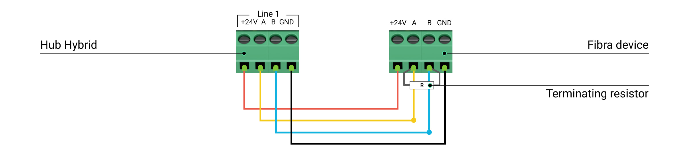
- Connect the wires to the terminals according to the diagram below. Follow the polarity and connection order of the wires. Securely fasten the conductors to the terminals.
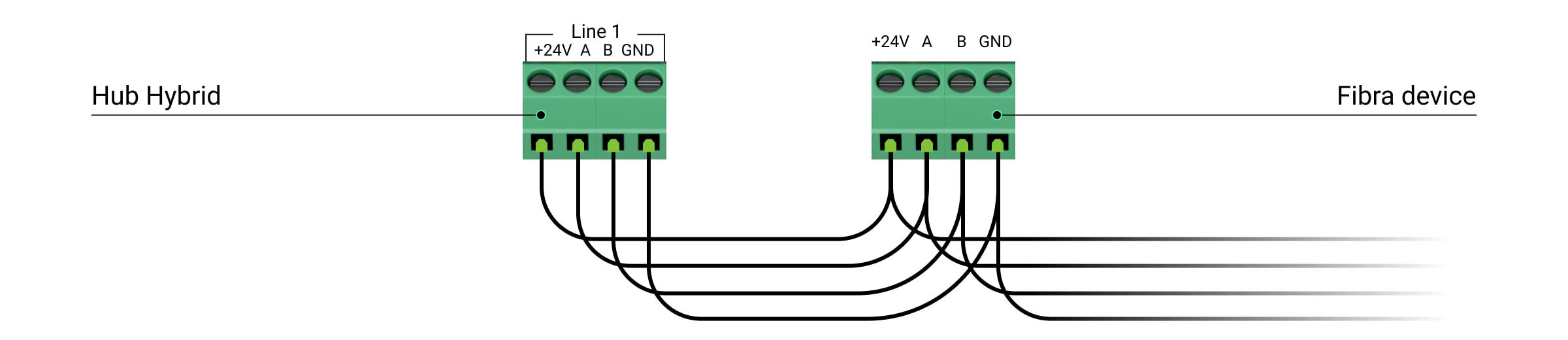
+24V — power supply terminal of 24 V⎓.
А, B — signal terminals.
GND — power ground terminal. - When using Beam (Radial) topology: if the integration module is the last in a line, install a terminating resistor by connecting it to the signal terminals of the device. For the Ring topology terminating resistor is not needed.
If possible, we recommend connecting devices using the Ring topology (hub—device—hub). This improves the antisabotage protection of the system.
- Secure the cables with cable ties using special mounts in the casing.
- Install a 12V⎓ backup battery on the special holders in a casing. Please note that Superior MultiTransmitter Fibra cannot be connected to third-party power supply units.
Use 12 V⎓ batteries with a capacity of 4 or 7 A∙h. For such batteries, special holders in the casing are designed. You can also use similar batteries of a different capacity, of the matching size, and with a charging time of no more than 40 hours. The maximum dimensions of the battery to be installed in the casing are 150 × 65 × 94 mm, and the weight is 5 kg.
- Connect the backup battery with the bundled cable to the board terminals according to the wiring diagram below. Follow the polarity and connection order of the wires. Securely fasten the conductors to the terminals.
- Connect the external 100-240 V~ power supply to the integration module.
- Connect the backup battery and external power supply to the hub. Turn on the hub.
- Add an integration module to the system.
- Run a Fibra signal strength test. The recommended signal strength is two or three bars. If the signal strength is one or zero bars, check the connection’s correctness and the cable’s integrity.
- Install the lid on the integration module casing. Secure it with screws at the bottom and top of the lid using the bundled hex wrench.
Connecting wired devices to Superior MultiTransmitter Fibra
- Remove the Superior MultiTransmitter Fibra casing lid by unscrewing the bottom and top screws with the bundled hex wrench.
- Turn off Superior MultiTransmitter Fibra by holding down the on/off button.
- Disconnect 100-240 V~ external power and Superior MultiTransmitter Fibra backup battery.
- Select the Superior MultiTransmitter Fibra zone to which you want to connect a device.
- Pull the third-party device cable into the integration module casing.
- Connect the device to Superior MultiTransmitter Fibra, securely fixing the wires in the terminals. The wiring diagram can be found in the user manual provided by the manufacturer of the wired device.
Read the manufacturer’s instructions before connecting the device to Superior MultiTransmitter Fibra.
- Secure the cable with cable ties using special mounts inside the casing.
- Connect 100-240 V~ external power and backup battery to Superior MultiTransmitter Fibra.
- Add device to the system.
- Test the operation of the connected wired device.
Adding to the system
Check the device compatibility before adding to the system. Only verified partners can add and configure Fibra devices in Ajax PRO apps.
Before adding a device
- Install an Ajax PRO app.
- Log in to a PRO account or create a new one.
- Select a space or create a new one.
The space functionality is available for apps of such versions or later:
- Ajax Security System 3.0 for iOS;
- Ajax Security System 3.0 for Android;
- Ajax PRO: Tool for Engineers 2.0 for iOS;
- Ajax PRO: Tool for Engineers 2.0 for Android;
- Ajax PRO Desktop 4.0 for macOS;
- Ajax PRO Desktop 4.0 for Windows.
- Add at least one virtual room.
- Add a compatible hub to the space. Ensure the hub is switched on and has internet access via Ethernet, Wi-Fi, and/or mobile network.
- Ensure the space is disarmed, and the hub is not starting an update by checking statuses in the Ajax app.
Adding to the hub
- Open the Ajax PRO app. Select the hub to which you want to add Superior MultiTransmitter Fibra.
- Go to the Devices
 tab and tap Add device.
 - Select Add all Fibra devices. The hub will scan the Fibra lines. After scanning, all devices connected to the hub that still need to be added to the system will be shown.
Scanning is also available in the Lines menu:
Hub → Settings
 → Lines → Add all Fibra devices.
 - Select the device from the list. After pressing, the LED indicator will flash to identify this device.
- Set the device name, and specify the room and security group if Group mode is enabled.
- Tap Save.
The device connected to the hub will appear in the list of hub devices in the Ajax app.
Once added to the hub, the integration module will appear in the list of hub devices in the Ajax app. The update frequency for device statuses in the list depends on the Jeweller/Fibra settings, with the default value of 36 seconds.
Superior MultiTransmitter Fibra works with one hub only. After connecting to a new hub, the integration module stops exchanging commands with the old one. After adding to the new hub Superior MultiTransmitter Fibra is not removed from the list of the old hub. You should do it manually in Ajax apps.
How to add a connected wired device
In the Ajax system, each connected to the Superior MultiTransmitter Fibra device occupies one slot within the hub’s device limit.
- In the Ajax PRO app, go to the Devices tab.
- Find Superior MultiTransmitter Fibra in the device list.
- Click on the Devices menu under the integration module icon.
- Click Add Device.
- Assign a name to the device.
- Select the wired zone to which the device will be physically connected.
- Select a virtual room and a security group if the Group mode is enabled.
- Press Add Device. The device will be added within 30 seconds.
The device status update depends on the Jeweller/Fibra settings; the value by default is 36 seconds.
If the connection fails, check if the wired connection is valid and try again. If the hub already has the maximum number of devices added (for Superior Hub Hybrid, the default is 100), you will get an error notification when you add one.
To perform the detection test, trigger the connected third-party device (for example, motion for motion detectors, etc.) The state of the third-party detector will be displayed in the app and on the device’s LED indicator if it is available.
Functionality testing
An Ajax system has several tests for choosing the right installation place for the devices. Tests do not start immediately, but after no more than one polling interval hub—device.
Fibra Signal Strength Test is available for Superior MultiTransmitter Fibra. The test allows you to determine the strength and stability of the signal at the installation site.
To run the test, in the Ajax PRO app:
- Select the required space.
- Go to the Devices tab.
- Select Superior MultiTransmitter Fibra in the list.
- Go to Settings
 .
. - Run the Fibra signal strength test.
Icons
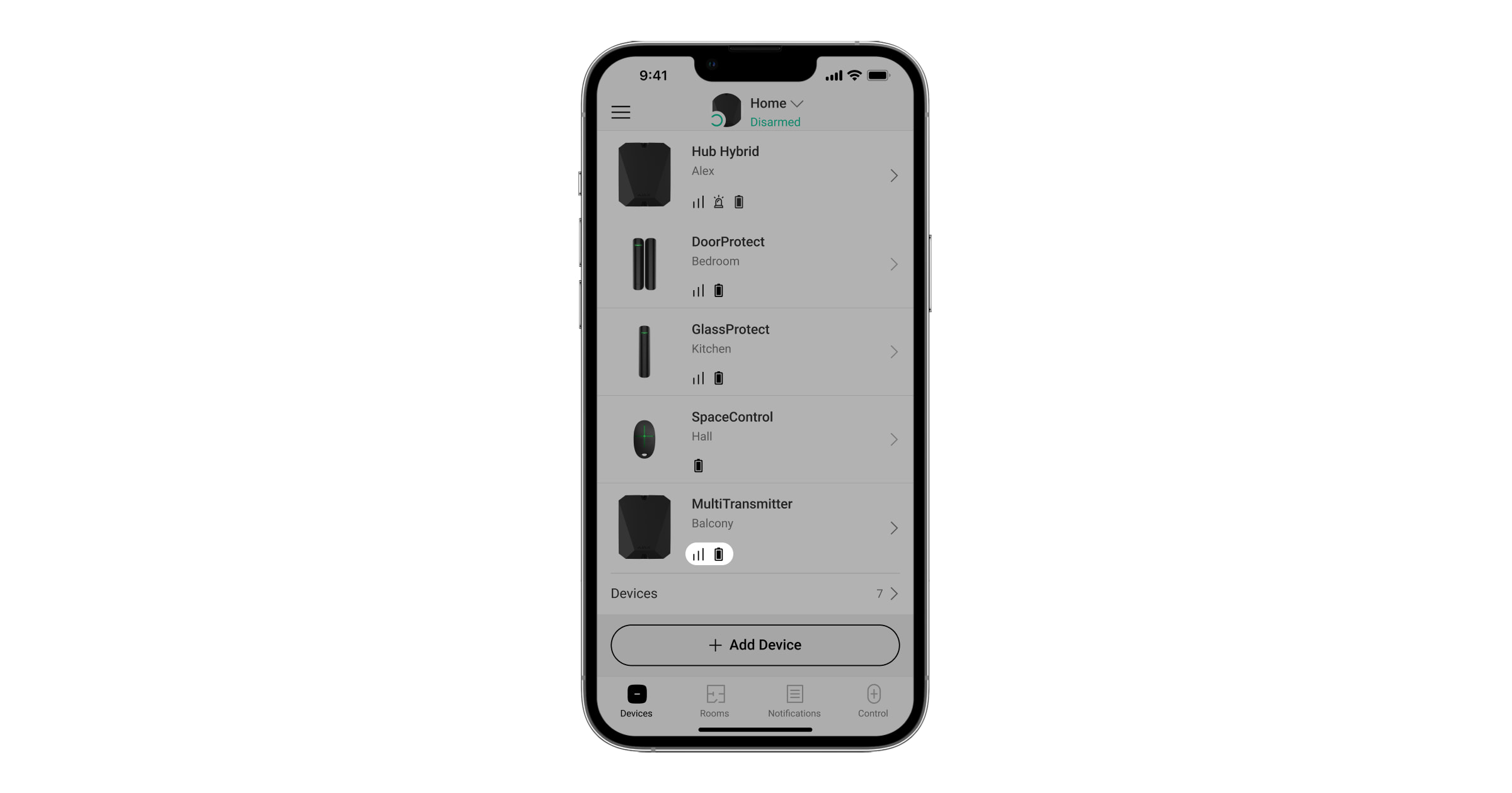
Icons show some device states. You can view them in Ajax apps in the Devices ![]() tab.
tab.
Superior MultiTransmitter Fibra icons
| Icon | Meaning |
|
Fibra signal strength — displays the signal strength between the hub and the integration module. Recommended value is 2–3 bars. |
|
| A fire detector connected to Superior MultiTransmitter Fibra has registered an alarm. | |
|
The charge level of the Superior MultiTransmitter Fibra backup battery. |
|
| Superior MultiTransmitter Fibra has a malfunction. A list of malfunctions is available in the States of the integration module. | |
|
Superior MultiTransmitter Fibra is disabled. |
|
|
Superior MultiTransmitter Fibra tamper triggering events are disabled. |
|
|
Superior MultiTransmitter Fibra is disabled until the first event of disarming the system. |
|
|
Superior MultiTransmitter Fibra tamper triggering events are disabled until the first event of disarming the system. |
|
| The device has lost connection with the hub or the hub has lost connection with the Ajax Cloud server. | |
|
The device has not been transferred to the new hub. |
Icons of connected devices
| Icon | Meaning |
| Chime function is enabled. | |
|
|
Delay When Entering and/or Exit is enabled. |
| The device operates in the Always active mode. | |
| The device will work when Night Mode is enabled. | |
|
The device state is OK. Displayed for EOL, NC, and NO connections only. |
|
|
The device is short-circuited. Displayed for EOL, NC, and NO connections only. |
|
| The device tamper state is OK.* | |
| Device tamper alarm.* | |
| The state of the intrusion sensors is OK.* | |
| Intrusion alarm.* | |
| The state of the auxiliary request button is OK.* | |
| Alarm when pressing the auxiliary request button.* | |
| The state of the alarm button is OK.* | |
| Alarm when the alarm button is pressed.* | |
| The state of the fire sensor is OK.* | |
| The device has detected a fire alarm.* | |
| The state of the gas sensor is OK.* | |
| Gas alarm.* | |
| The device state is OK.* | |
| Device malfunction is detected.* | |
| The state of the flooding sensor is OK.* | |
| Alarm caused by the flooding.* | |
| The state of the glass break sensor is OK.* | |
| Glass break alarm.* | |
| The state of the high temperature sensor is OK.* | |
| Alarm when the upper temperature limit is exceeded.* | |
| The state of the low temperature sensor is OK.* | |
| Alarm when the lower temperature limit is exceeded.* | |
| The state of the masking sensor is OK.* | |
| Masking alarm.* | |
| The state of the duress code device is OK.* | |
| Alarm triggered when the system is disarmed using the duress code.* | |
| The state of the vibration (seismic) sensor is OK.* | |
| Vibration (seismic) alarm.* | |
| The state of the device for which the custom type of event is selected is OK.* | |
| The alarm of the device for which the custom type of event is selected.* | |
| The sensor operates in the Switch arming modes mode. | |
| The state of the Blocking element. | |
| The state of the Bolt lock. | |
| The device is automatically disabled due to exceeding the number of alarms. | |
| The device is automatically disabled by the restoration timer. | |
| The device is disabled by the system user. | |
| The device is deactivated until the first event of disarming the system. |
* Icon is displayed for 2EOL and 3EOL connections only.
States
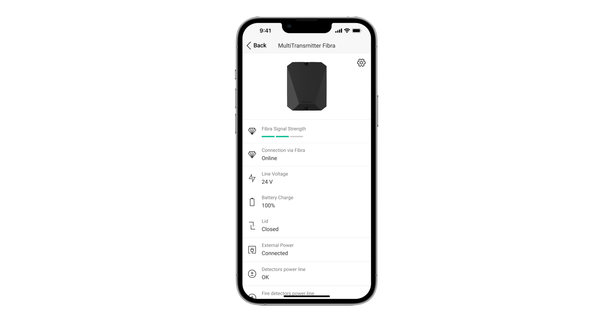
Superior MultiTransmitter Fibra states
The states contain information about the integration module and its operating parameters. Superior MultiTransmitter Fibra states can be found in the Ajax app:
- Go to the Devices tab.
- Select MultiTransmitter Fibra in the device list.
| Parameter | Meaning |
| Data import | Displays the error when transferring data to the new hub:
|
| Malfunction |
Pressing The field is displayed only if a malfunction is detected. |
| Fibra signal strength |
Signal strength between the hub and Superior MultiTransmitter Fibra. The recommended value is two or three bars. Fibra is the protocol for transmitting Superior MultiTransmitter Fibra events and alarms. |
| Connecting via Fibra | Connection state between the hub and Superior MultiTransmitter Fibra:
|
| Line voltage | The voltage value on the Fibra line to which the integration module is connected. |
| Battery charge |
The charge level of the connected battery. Specified as a percentage in 5% increments. |
| Lid | The state of the tampers that responds to detachment of the device from the surface or the casing opening:
|
| External power | The presence of external power supply 100–240 V~:
|
| Detectors Power Line | Status of power terminals of the third-party wired devices:
|
| Fire Detectors Power Line | Status of power terminals of third-party fire detectors:
|
| Permanent Deactivation | Shows the status of the device permanent deactivation function:
|
| One-Time Deactivation | Shows the status of the device permanent deactivation function:
|
| Firmware | Superior MultiTransmitter Fibra firmware version. |
| ID | Superior MultiTransmitter Fibra ID/serial number. Also located on the integration module board, the back part of the casing, and on the packaging. |
| Device No. | The Superior MultiTransmitter Fibra loop (zone) number. |
| Line No. | The number of the Fibra line of a hub to which Superior MultiTransmitter Fibra is physically connected. |
States of connected devices
The states display information about the device and its operating parameters. States of connected to Superior MultiTransmitter Fibra devices can be found in Ajax apps:
- Go to the Devices tab.
- Find Superior MultiTransmitter Fibra in the list.
- Click on Devices under the Superior MultiTransmitter Fibra icon.
- Select the device from the list.
| Parameter | Meaning |
| Malfunction |
After clicking on The field is displayed only if a malfunction is detected. |
| Superior MultiTransmitter Fibra name | The state of Superior MultiTransmitter Fibra that the wired device is connected to:
|
|
Device State Displayed for Without EOL and EOL connection types |
The status of the connected wired device:
|
|
Tamper Sensor Displayed for 2EOL and 3EOL connection types |
Tamper status of the connected device:
|
|
“Name of the selected event type” Sensor Displayed for 2EOL and 3EOL connection types |
The status of the connected wired device:
|
| Always Active |
If the option is active, connected to Superior MultiTransmitter Fibra device is constantly armed and reports alarms. You can configure the option only for certain event types. |
|
Device Resistance Displayed for EOL, 2EOL, and 3EOL connection types |
The total resistance of the resistor (or resistors) connected to the device is measured automatically. Values can also be set manually in 100-ohm increments. |
| Permanent Deactivation |
Allows the user to disable the device without removing it from the system. Two options are available:
You can also separately configure the device disconnecting:
The feature is configured in the Ajax PRO apps. |
| One-Time Deactivation | Shows the status of the device one-time deactivation setting:
|
| Alarm Reaction | |
| Operating Mode | Shows how the detector reacts to alarms:
|
| Delay When Entering, s |
Delay time when entering: 5 to 120 seconds. Delay when entering (alarm activation delay) is the time the user has to disarm the security system after entering the secured area. |
| Delay When Leaving, s |
Delay time when leaving: 5 to 120 seconds. Delay when leaving (arming delay) is the time the user has to leave the secured area after arming. |
| Arm in Night Mode | When this option is enabled, the device will enter the armed mode when the system is set to Night Mode. |
| Night Mode Delay When Entering, s |
Delay time when entering in Night Mode: 5 to 120 seconds. Delay when entering (alarm activation delay) is the time the user has to disarm the security system after entering the secured area. |
| Night Mode Delay When Leaving, s |
Delay when leaving in Night Mode: 5 to 120 seconds. Delay when leaving (arming delay) is the time the user has to leave the secured area after arming. |
| Wired devices № | Superior MultiTransmitter Fibra zone number, to which a wired detector or device is physically connected. |
| Device No. | Device loop (zone) number. |
Settings
Superior MultiTransmitter Fibra settings
To change the Superior MultiTransmitter Fibra settings:
- Go to the Devices tab.
- Select Superior MultiTransmitter Fibra from the list.
- Go to Settings by clicking on the gear icon .
- Set the parameters.
- Click Back to save the new settings.
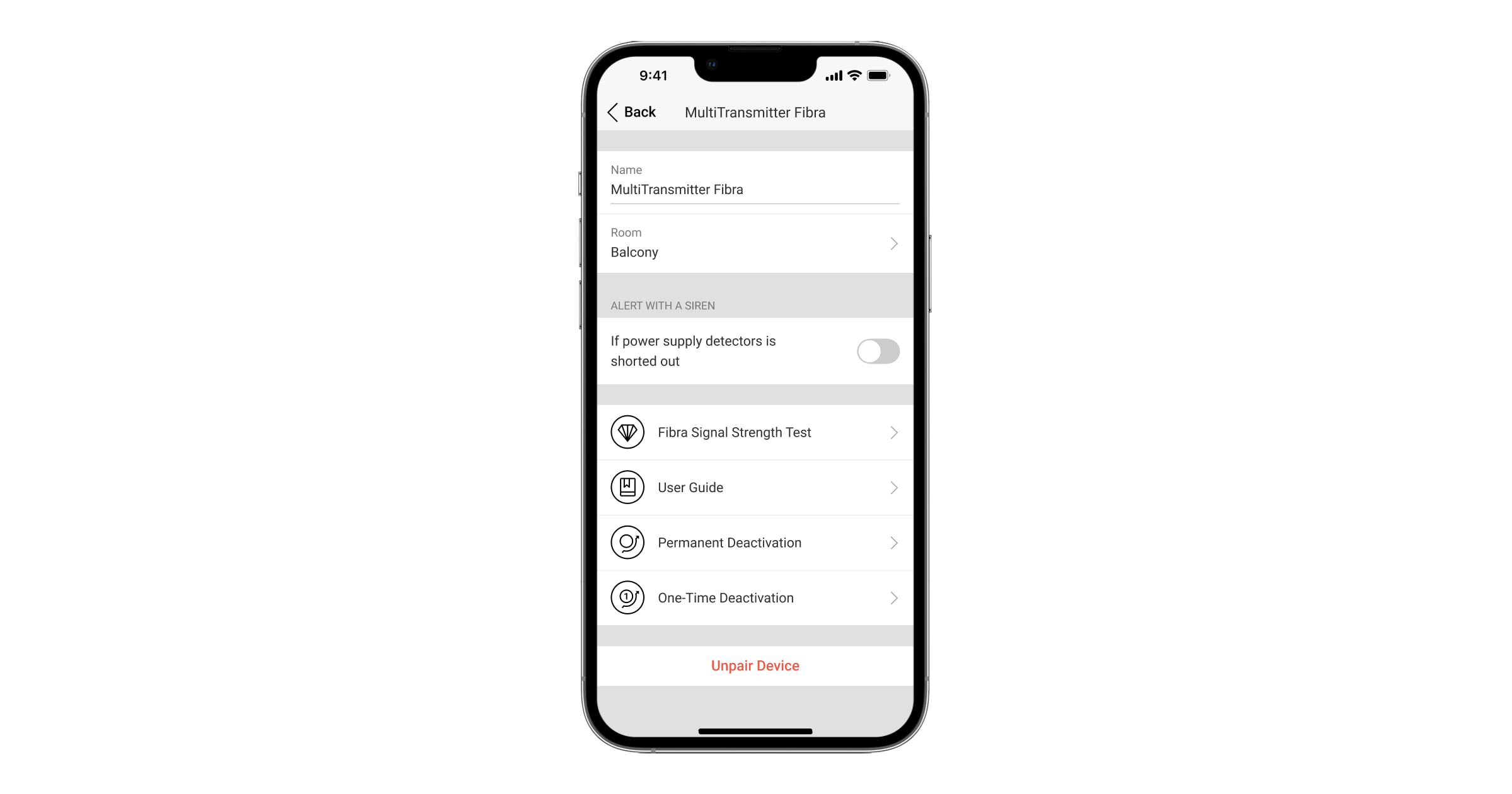
| Settings | Meaning |
| Name |
Integration module name. Displayed in the list of hub devices, SMS text, and notifications in the event feed. To change the name, click on the text field. The name can contain up to 12 Cyrillic characters or up to 24 Latin characters. |
| Room |
Choosing a Superior MultiTransmitter Fibra virtual room. The room name is displayed in the text of SMS and notifications in the event feed. |
| Notify of connected devices’ resistance failures |
If the option is deactivated, the system will not notify you of incorrect resistor connections. This function is supported by Superior MultiTransmitter Fibra integration modules with firmware version up to and including 2.20 and hubs with OS Malevich 2.22 and later and in applications of such versions and later:
|
| Alert with a siren if power supply for detectors is shorted out | If the option is active, the sirens connected to the system are activated when a short circuit is detected in the power supply line of devices connected to the integration module. |
| Fibra Signal Strength Test |
Switches the integration module to the Fibra Signal Strength Test mode. The test allows you to check the Fibra signal strength between the hub and the integration module to find the optimal installation spot. |
| User Guide | Opens Superior MultiTransmitter Fibra user manual in the Ajax app. |
| Permanent Deactivation |
Allows the user to disable the device without removing it from the system. Three options are available:
The system only ignores the disabled device. Devices connected via Superior MultiTransmitter Fibra will continue to operate in normal mode. The system can also automatically deactivate devices when the set number of alarms is exceeded or when the restoration timer expires. |
| One-Time Deactivation |
Allows the user to disable events of the device until the first event of disarming the system. Three options are available:
The system only ignores the disabled device. Devices connected via Superior MultiTransmitter Fibra will continue to operate in normal mode. |
| Unpair Device | Disconnects Superior MultiTransmitter Fibra from the hub, and deletes its settings. |
Settings of connected devices
To change the connected device settings, in the Ajax app:
- Go to the Devices tab.
- Find Superior MultiTransmitter Fibra in the list.
- Click on Devices under the Superior MultiTransmitter Fibra icon.
- Select the device from the list.
- Go to Settings by clicking on the gear icon .
- Set the parameters.
- Click Back to save the new settings.
| Setting | Meaning |
| Name |
Wired device name. Displayed in the list of hub devices, SMS text, and notifications in the event feed. To change the name, click on the text field. The name can contain up to 12 Cyrillic characters or up to 24 Latin characters. |
| Room |
Selecting the device’s virtual room. The room name is displayed in the text of SMS and notifications in the event feed. |
| Input type | Selecting the connection type of a third-party device:
|
| Default State | Selecting the normal contact state of the connected detector or device:
|
| Sensor Mode |
Selecting the sensor mode of the connected device:
|
| Arm Switch Settings | Configuring the arm switch if the Switch Arming Modes option is selected for the Sensor Mode setting:
|
| Type of Event |
Selecting an event type for the connected device. Refer to Event types of wired devices section for more information. The text of notifications in the event feed and SMS, as well as the code transmitted to the security company monitoring station depends on the selected event type. This setting is available if Detect alarms option is selected for the Sensor mode setting. |
| Operating Mode | The operating mode of the connected device:
Be sure to set a type that matches the connected device. The pulsed detector in the bistable mode generates unnecessary restoration events. A bistable detector in pulsed mode, on the contrary, will not send restoration events. |
| Always Active |
If the option is active, connected to Superior MultiTransmitter Fibra device is constantly armed and reports alarms. You can configure the option only for certain event types. This setting is not available if Switch arming modes option is selected for the Sensor mode setting. |
| Notify of changes in bolt lock state |
If the option is enabled, the system will notify the user each time the bolt lock change it’s state. This option is available if the Control of bolt lock option is selected for the Sensor mode setting. |
| Pulse Time | Pulse time of a detector or device for detecting an alarm:
An alarm will be activated if the pulse from the device lasts longer than specified in this setting. This can be used to filter false triggerings. |
| Alert with a siren if alarm detected |
If the option is active, the sirens connected to the system are activated when an alarm is detected. This setting is available if Detect alarms option is selected for the Sensor mode setting. |
| Chime Settings |
Opens the Chime settings. The function works only for bistable devices. Notifications will not work for sensors in pulse mode or Always active mode. |
| Alarm Reaction | |
| Operating Mode | Specify how this device will react to alarms:
|
| Delay When Entering, s |
Delay time when entering: 5 to 120 seconds. Delay when entering (alarm activation delay) is the time the user has to disarm the security system after entering the secured area. |
| Delay When Leaving, s |
Delay time when leaving: 5 to 120 seconds. Delay when leaving (arming delay) is the time the user has to leave the secured area after arming the system. |
| Arm in Night Mode |
If the option is active, the device connected to the integration module will switch to armed mode when the system is set to Night Mode. |
| Night Mode Delay When Entering, s |
Delay time when entering in Night Mode: 5 to 120 seconds. Delay when entering (alarm activation delay) is the time the user has to disarm the security system after entering the secured area. |
| Night Mode Delay When Leaving, s |
Delay when leaving in Night Mode: 5 to 120 seconds. Delay when leaving (arming delay) is the time the user has to leave the secured area after arming. |
| Permanent Deactivation |
Allows the user to disable the device without removing it from the system. Two options are available:
You can also separately configure disconnecting of the device:
The feature is configured in the Ajax PRO apps. |
| One-Time Deactivation |
Allows the user to disable events of the device until the first event of disarming the system. Two options are available:
|
How to set up Chime
When Chime are enabled, the sirens make a special sound to indicate that the opening detectors are triggered when the system is disarmed. The feature is used, for example, in stores, to notify employees that someone has entered the building.
Chime is set in two stages: setting up opening detectors and setting up sirens.
How to set up wired opening detector
Before setting up the Chime feature, make sure that a wired opening detector is connected to Superior MultiTransmitter Fibra and the following options have been configured in the detector settings in the Ajax app:
- The event type is intrusion.
- Operating mode: bistable.
- Always active — disabled.
- Go to the Devices tab.
- Find Superior MultiTransmitter Fibra in the list.
- Click on the Devices menu under the integration module icon.
- Select the device from the list.
- Go to the device Settings by clicking on the gear icon .
- Go to the Chime settings menu.
- Activate the If sensor is triggered option.
- Select the chime sound: 1 to 4 short beeps. After that, the Ajax app will play the selected sound.
- Click Back to save the settings.
- Set up the siren.
How to reset fire detectors alarm
In case of alarms of the fire detectors connected to Superior MultiTransmitter Fibra, the window prompting of the need to reset the alarms is displayed in the Ajax app. This permits the detectors to return to their normal state and further respond to a fire.
If the detectors are not reset after the fire alarm, they will not respond to the next fire, as they will remain in alarm mode.
There are two ways to reset fire detectors:
- By clicking the button in the notification in the app.
- Via the Superior MultiTransmitter Fibra menu: click on the red button opposite the integration module.
Indication
The Superior MultiTransmitter Fibra LED indicator may light up in white, red, or green depending on the device status.
In the previous Superior MultiTransmitter Fibra casing version, the LED indicator is not visible when the casing lid is closed. You can check the device status only in the Ajax app.
The new Superior MultiTransmitter Fibra casing version features light guides, allowing the integration module state to be viewed at any time.
| LED indication | Event | Note |
| Lights up in white. | Superior MultiTransmitter Fibra is connected to the hub. The external power supply is disconnected. | |
| Lights up in red. | Superior MultiTransmitter Fibra is not connected to the hub. | For example, the hub is turned off or the integration module has no connection with the hub via the Fibra protocol. |
| Once every 10 seconds, lights up in green for 1 second and goes out. | The external power supply is disconnected. |
Lights up in white if there is connection with hub. Lights up in red if there is no hub connection. |
| Goes out, and then lights up in green and gradually goes out to complete disabling. | Turning off Superior MultiTransmitter Fibra after holding down the on/off button. | |
| Smoothly lights up and goes out after an alarm or a tamper trigger |
Low voltage of the power supply line. Voltage of 7 V⎓ or less is considered low. |
Malfunctions
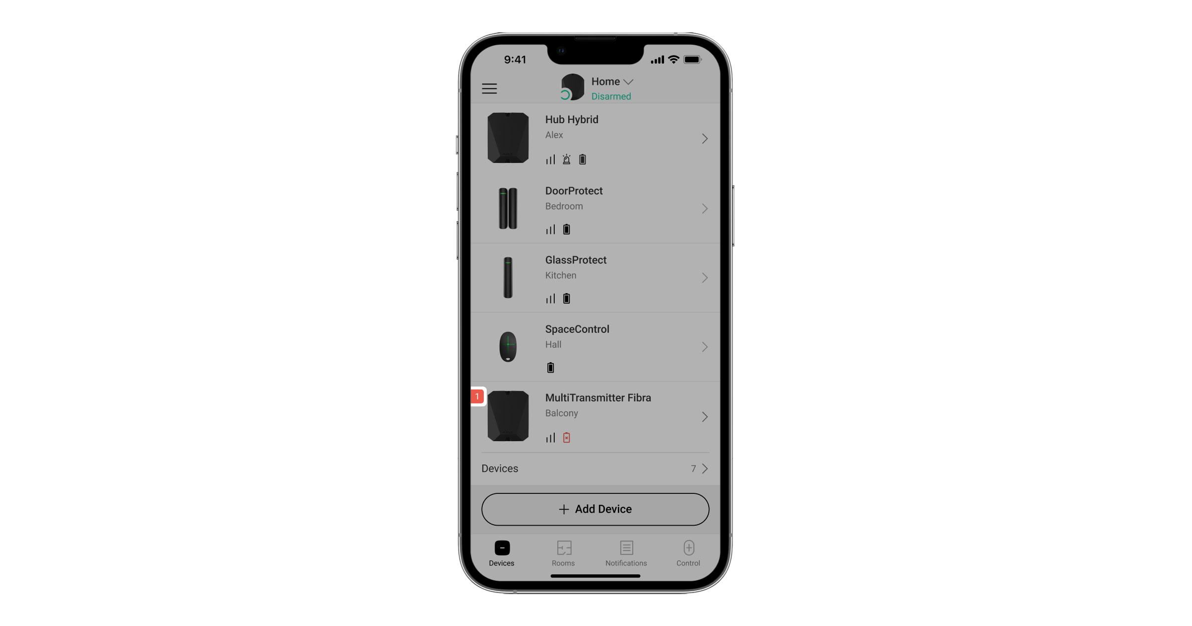
If a malfunction is detected in the integration module or a wired device connected to it, a malfunction counter will be displayed in Ajax apps in the upper left corner of the device icon.
All malfunctions can be seen in the States of devices. Fields with malfunctions will be highlighted in red.
The integration module and wired devices connected to it can report malfunctions to the security company monitoring station as well as to users in the form of push notifications and SMS.
Superior MultiTransmitter Fibra malfunctions
- The casing of the integration module is open or torn off from the surface (tampers triggering).
- No connection between the integration module and the hub via the Fibra protocol.
- Battery discharged.
- Battery charges over 40 hours.
- The backup battery connection failed (the battery is not physically connected or there are hardware problems: for example, the connection cable is defective).
- Low voltage of Superior MultiTransmitter Fibra power supply line.
- The power supply line of detectors is short-circuited.
Malfunctions of connected devices
- The device enclosure is open (tamper triggering).
- No connection between the integration module and the device (contacts damaged).
- Incorrect connection of resistors (resistor resistance error).
- The system detected a short circuit in the device contacts.
Maintenance
Regularly check the functionality of the integration module and wired devices connected to it. The optimal frequency of check is once every three months. We recommend you check the fixation tightness of the wires in the terminals of the integration module.
Clean the casing from dust, cobwebs, and other contaminants as they emerge. Use a soft dry cloth suitable for equipment care. Do not use substances that contain alcohol, acetone, gasoline, and other active solvents to clean the device.
Technical specifications
Warranty
The warranty for the Limited Liability Company “Ajax Systems Manufacturing” products is valid for 2 years after purchase.
If the device does not function correctly, please contact the Ajax Technical Support first. In most cases, technical issues can be resolved remotely.
Contact Technical Support:
Manufactured by “AS Manufacturing” LLC
