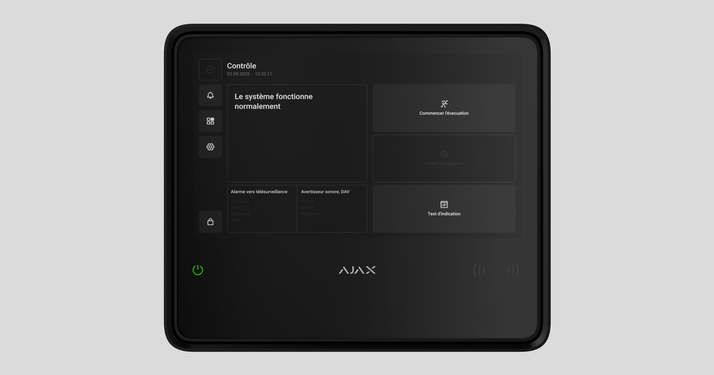
Type4 Fire Hub Jeweller is a wireless fire alarm central unit for a fire alarm system. The device complies with Type 4 fire alarm equipment requirements. The central unit features a 10.1″ touch display that provides informative fire alarm notifications, system status updates, and convenient fire system control.
The central unit requires an internet connection to access the Ajax Cloud server. Supported communication channels include Ethernet, Wi-Fi, and two SIM cards.
Type4 Fire Hub Jeweller can operate autonomously for 24 or 72 hours, depending on the battery. The backup battery is not included in the complete set. Only use compatible batteries: Type4 Internal Battery (24h) or Type4 Internal Battery (72h).
Functional elements
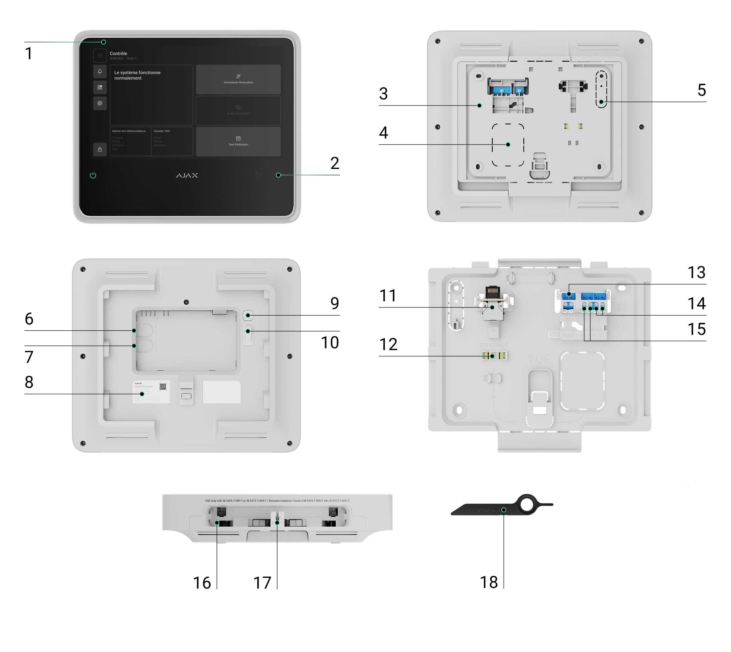
- IPS touch display with a 10.1″ diagonal.
- Card/key fob reader (coming soon).
- SmartBracket mounting panel.
- Perforated part of the mounting panel for routing cables through the wall.
- Perforated part of the mounting panel that triggers the tamper button if the device is removed from the surface. Do not break it off.
- Slot for micro SIM 2.
- Slot for micro SIM 1.
- QR code and ID (serial number) of the device.
- Power button.
- Tamper button.
- Ethernet cable connector.
- Bubble level for checking mount inclination angle during installation.
- Terminals for connecting a power cable. Note: mains terminals are not polarity-sensitive — live and neutral wires can be connected to any terminal.
- Relay output 2 — for alerting the monitoring station to fire alarms.
- Relay output 1 — for alerting the monitoring station to system faults.
- Slot for internal battery (not included).
- Hole for the special tool.
- Special tool (key).
LED indicators
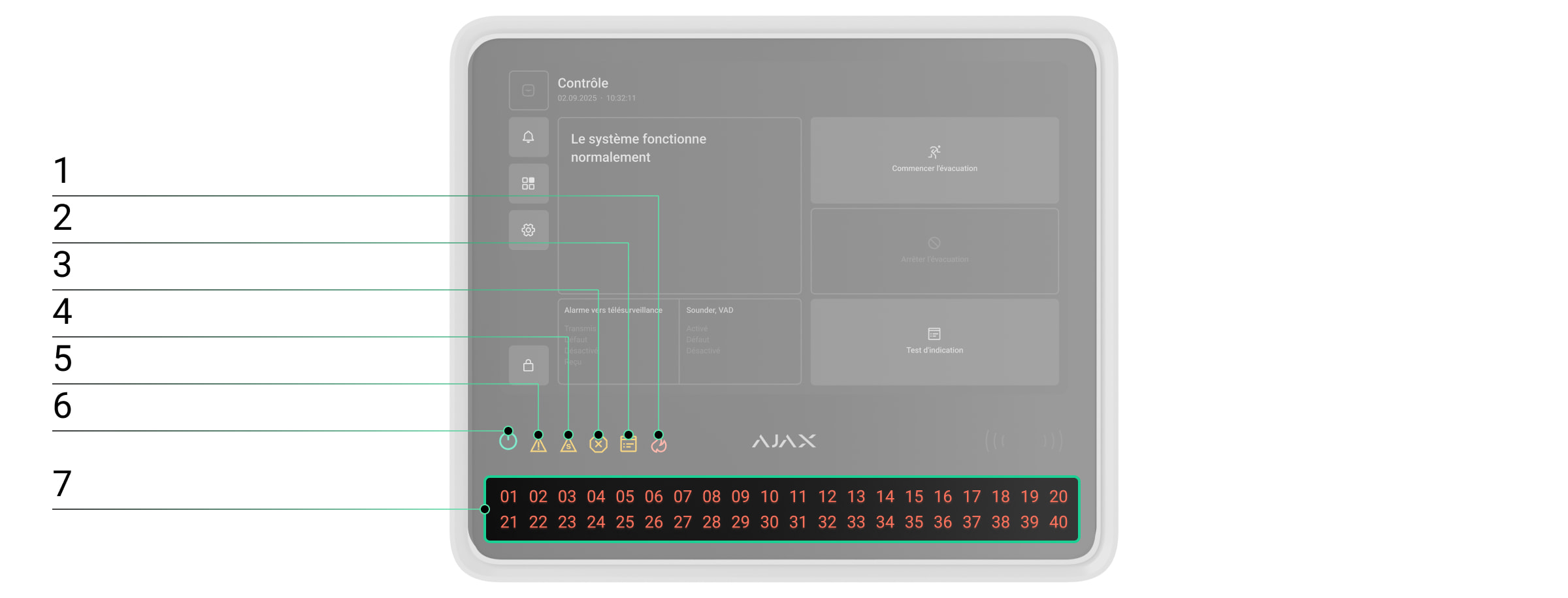
- Fire alarm indicator.
- Test indicator.
- Disablement indicator.
- System fault indicator.
- Fault indicator.
- Power supply indicator.
- Fire zones LED indicators.
Operating principle
Type4 Fire Hub Jeweller is the fire alarm central unit of an Ajax system, designed for comprehensive management of fire safety systems. It also supports video surveillance and automation devices, making it a unified solution for protecting commercial and municipal sites. The central unit controls the operation of connected devices and indicates the current state of the fire safety system.
The central unit is added to a space — a virtual entity that brings together various autonomous devices installed at the same facility.
You can connect up to 200 wireless Ajax devices to Type4 Fire Hub Jeweller. To monitor the operation of all connected devices, the central unit communicates with them using two encrypted protocols:
1. Jeweller is a radio protocol for transmitting events and alarms from Ajax wireless devices. The communication range is up to 1,800 m in open space, without obstacles such as walls, doors, or inter-floor structures.
2. Wings is a radio protocol for transmitting large data packets. The communication range is also up to 1,800 m in open space.
If a fire detector is triggered, the system raises an alarm within three seconds. In this case, the central unit activates the sirens, runs scenarios, and alerts the monitoring station and all users.
Fire protection
Type4 Fire Hub Jeweller is fully compliant with key fire detection and fire alarm system standards, specifically Type4. It allows building wireless fire detection and alarm systems in commercial and municipal facilities.
Ajax devices from the Type4 Line connected to the central unit are assigned to one of 40 Fire zones. When a fire is detected in any zone or an Ajax manual call point is pressed, all Ajax Type4 sounders and visual alarm devices (VADs) across the facility raise an alarm.
The central unit display shows complete incident information: the cause of the alarm, the time it started, and where (zone, room, location), along with the last activated zone and the total number of zones in the fire alarm state.
Thanks to its intuitive interface and detailed LED indication, users can quickly respond to alarms, locate the fire, or activate the evacuation manually.
Users with the appropriate rights and access level can control the fire alarm from the central unit display or via Ajax apps: Control ![]() tab → tap the
tab → tap the ![]() icon. The Control tab provides the following actions:
icon. The Control tab provides the following actions:
- Start evacuation — activates sounders and VADs;
- Stop evacuation — silences sounders and VADs;
- Indication test — run the central unit indication test.
The alarm can be reset only after all fire signals in the system have been cleared.
Event center
Ajax apps keep a detailed log of alarms, events, and user actions. The central unit display also shows an event log, limited to Ajax Type4 devices connected to the central unit. The Event center tab provides detailed information about fire alarms, device faults, disablements, tests, and other important events. The information is organized into separate tabs for easier navigation.
Fire alarm tab
The Fire alarm tab becomes active only when a fire is detected in the system. Tapping this tab opens a list of zones currently in the fire alarm state, sorted by the time the fire started. Selecting a zone from the list displays the alarms registered in that zone.
Fault, test, or disablement tab
The Fault, test, or disablement tab displays all active system events matching the types listed in its name. The tab becomes active only when the system is running a test of Ajax Type4 devices, when some devices are fully or partially disabled, or when a fault has occurred within the fire alarm system, and it has not yet been restored. Tapping this tab opens a list of the corresponding system events.
Event log tab
The Event log tab is always active. Tapping it opens a chronological list of all events and alarms related to the fire alarm system. The central unit event log stores up to 5,000 events.
Fire zones
Type4 Fire Hub Jeweller allows for managing Ajax Type4 devices in different Fire zones. Users can quickly access the Fire zones list from the central unit display to view the current state of each zone and check for any device disablements within them. An admin or a user with access level 2 can initiate a test or disable devices directly from the central unit touch screen.
Authorization
Unauthorized users have access to the central unit Control tab and can perform basic actions: start an indication test, start and stop evacuation.
Authorized users with access level 2 or higher have access to the broader central unit functionality, such as starting evacuation, silencing alarms, running device tests, etc.
Available authorization methods:
- Entering an access code on the central unit display.
Access level 2 can be configured in Ajax apps:
- For admins — in the Users section of the space settings.

An admin with system configuration rights is assigned access level 2 by default. Only a PRO with system configuration rights can manage admin permissions in Ajax PRO apps.
To disable the Fire system access level 2 toggle, the System settings toggle must be disabled first.
- For unauthorized users — in the Access codes section of the central unit settings.
Settings
In the Settings tab on the Type4 Fire Hub Jeweller display, users can adjust the screen backlight brightness and select the interface language. These options are available to all users.
All other central unit settings can be configured via Ajax apps.
Sabotage protection
Type4 Fire Hub Jeweller supports four communication channels for connecting to the Ajax Cloud server: Wi-Fi, Ethernet, and two SIM cards. This allows the device to work with multiple communication providers at once. If one channel becomes unavailable, the central unit automatically switches to another and notifies the monitoring station and system users.
If a jamming attempt is detected, the system switches to an idle radio frequency and sends notifications to the monitoring station and users.
The central unit regularly checks the connection quality with all linked devices. If any device loses connection, and the configured timeout expires, all system users (depending on the settings) and the monitoring station will receive a notification of the incident.
No one can turn off the central unit unnoticed. If an intruder attempts to open the central unit enclosure, a tamper alarm is triggered immediately. An alarm notification is then sent to the monitoring company and all system users.
The central unit regularly checks its connection to Ajax Cloud. The ping interval is defined in the central unit settings. When the minimum interval is configured, the server can notify users and the monitoring company as soon as 60 seconds after the connection is lost.
A 5 Ah or 10 Ah backup battery can be installed in the central unit. Type4 Internal Battery (24h) provides up to 24 hours of autonomous system operation, while Type4 Internal Battery (72h) offers up to 72 hours.
Internal battery is not included in the central unit complete set and must be bought separately.
OS Malevich
Type4 Fire Hub Jeweller runs on OS Malevich, a real-time operating system protected against viruses and cyberattacks.
OS Malevich brings new features and functionality to the Ajax system through over-the-air updates. A PRO or a company with firmware update rights can start an update — when available — from the Type4 Fire Hub Jeweller field in the Devices ![]() tab, or via the central unit states or settings. On-screen instructions help guide the user through the process.
tab, or via the central unit states or settings. On-screen instructions help guide the user through the process.
The update takes up to 2 minutes and requires the system to be disarmed, free of active fire alarms, and connected to an external power supply.
Ajax account
To set up the system, install an Ajax app and log in to your account, or create a new one if you don’t have one. Don’t create a new account for each space, since one account can manage multiple security systems. Where necessary, you can configure separate access rights for each space. Changing the space admin, adding or removing users does not reset the settings of devices added to the space.
Adding the central unit in an Ajax app
We highly recommend creating personal access codes, as well as access codes with access level 2, after adding Type4 Fire Hub Jeweller to a space. A code is required to log in and manage the fire alarm system from the central unit touch screen.
Use the latest versions of Ajax apps to access all available features and ensure proper system operation.
After adding a central unit to your account, you become the admin of the device. Admins can invite other users to the system and determine their rights. You can connect up to 200 users to Type4 Fire Hub Jeweller. Each PRO account connected to the central unit, as well as the security company profile, is considered a user of the system.
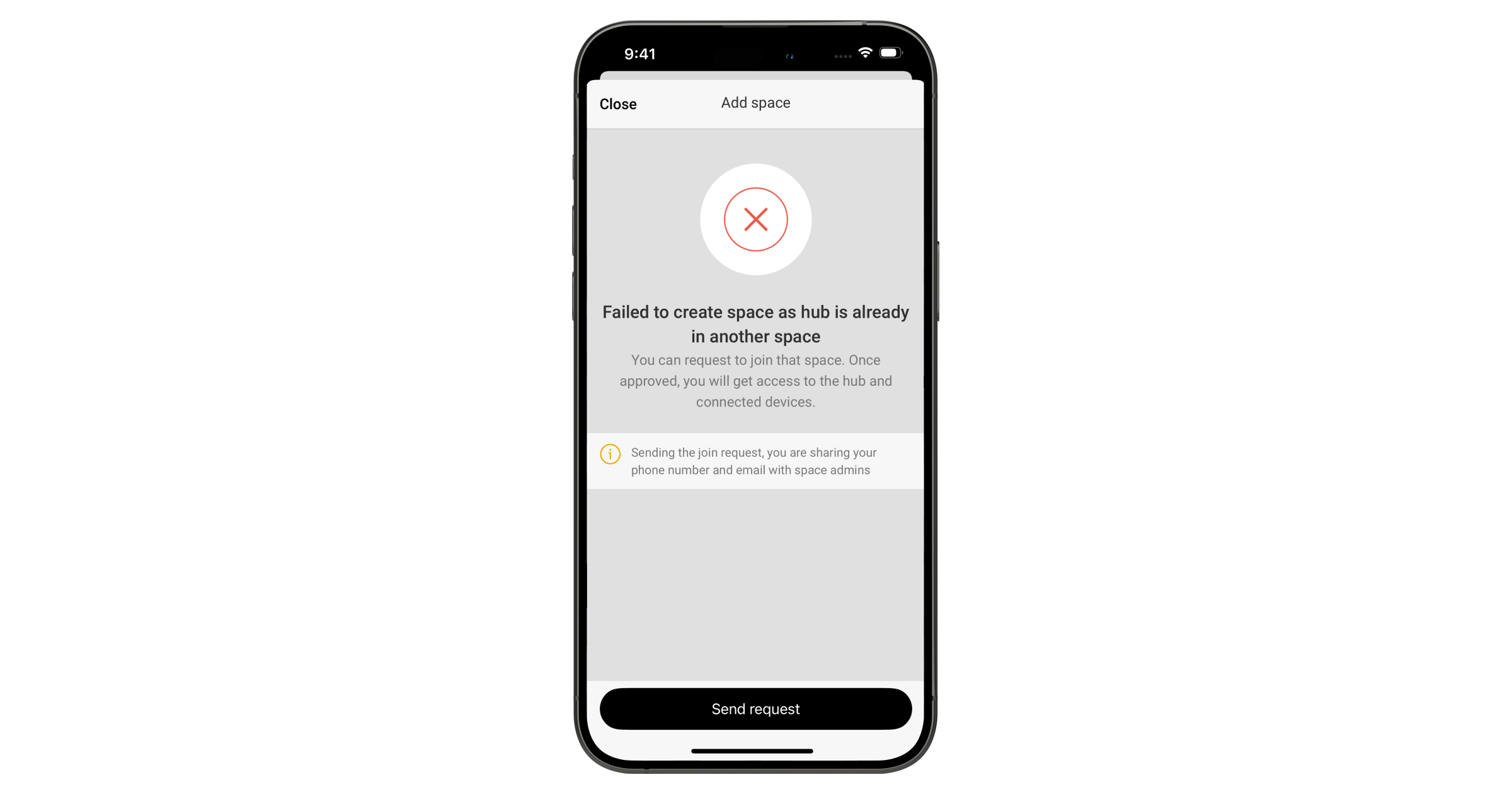
If there are already users on the central unit, the central unit admin, PRO with the rights to configure the system, or the installation company maintaining the selected central unit can add your account. You will be notified that the central unit has already been added to another account. Contact our Technical Support to determine who has admin rights on the central unit.
To add the central unit in an Ajax app:
- Connect external power, internal battery, Ethernet, and/or Wi-Fi and SIM cards to the central unit.
- Open an Ajax app and allow the requested permissions. This ensures full functionality and reliable delivery of alarm and event notifications.
- Make sure you have a space in the app. If not, create one.
- Scan the central unit QR code or enter its ID manually.
- Assign a name to the central unit.
- Add at least one virtual room.
- Turn on the central unit.
- Install the central unit on the SmartBracket mounting panel.
- Click Add device.
- Wait until the central unit is added. Once connected, the central unit will appear in the Devices
 tab of an Ajax app.
Adding devices to the central unit
Check the device compatibility before adding it to the central unit. To add a device to the central unit, it should be located within the central unit radio communication range — at the same secured premises.
To add a device to the central unit:
- Select a space with a compatible central unit.
- Ensure the central unit is switched on and has internet access via Ethernet, Wi-Fi, and/or mobile network.
- Check the states in an Ajax app to ensure the space is disarmed and the central unit is not starting an update.

Only a PRO or a space admin with the rights to configure the system can add a device to the central unit.
- Go to the Devices tab and tap Add device.
- Scan the QR code or enter the device ID manually. A QR code with ID is placed on the device under the SmartBracket mounting panel. Also, it is duplicated on the device packaging.
- Assign a name to the device.
- Select a virtual room.
- For Ajax Type4 devices, select a fire zone. If necessary, specify the device location in the Location field.
Names of devices, fire zones, rooms, and locations are displayed in the text of events and alarms of the Ajax system.
- Tap Add device, and the countdown will begin.
- Switch on the device.
Find more information in the user manual for each device how to add it to the central unit. The device connected to the central unit will appear in the list of central unit devices in the Ajax app. You can find the device by entering part of the name, model, or ID in the search field.
Faults
When a central unit fault is detected (e.g., the tamper alarm is triggered, the internal battery is low, the device is offline), the Ajax app displays a fault counter on the device icon. Faults are also indicated in the device’s states. Affected fields are highlighted in red.
All faults related to Ajax Type4 devices and the central unit itself are shown on its display. In the Control tab, users can see which zone requires attention and the reason. The LED indicators of the central unit always signal the presence of a fault.
More details about the fault can be found in the Event center or Fire zones tab on the central unit. Full information about the fire alarm system is also available in Ajax apps: Control ![]() tab → Swipe or tap the
tab → Swipe or tap the ![]() icon.
icon.
Icons
Icons display some of the Type4 Hub (4G) Jeweller states. The icons are displayed in the Devices ![]() tab in an Ajax app.
tab in an Ajax app.
| Icon | Meaning |
| The central unit operates in the 2G network. | |
| The central unit operates in the 4G (LTE) network. | |
| No SIM cards. Insert at least one SIM card. | |
| The SIM card is faulty or has a PIN code set up. Check SIM card operation in the phone and disable the PIN code request. | |
| The central unit battery charge level. Displayed in 1% increments. | |
| The backup battery is not connected. | |
| Type4 Fire Hub Jeweller fault detected. Open central unit states for details. | |
|
The central unit is directly connected to the monitoring station of the security company. The icon is not displayed if direct connection is not available or not configured. |
|
|
The central unit is not directly connected to the monitoring station of the security company. The icon is not displayed if direct connection is not available or not configured. |
States
In the central unit Control tab
Users can check the fire alarm system states in the central unit Control tab. It shows whether the system operates normally, if a fire alarm is active, and other system states.
| Parameter | Meaning |
| System state | The system state field is located in the upper-left corner of the central unit and shows the following state:
This field also contains additional details about the state, which can be checked in the Event center. |
| Alarm signal to CMS | Signal sending status to the monitoring station:
|
| Sounder, VAD | The state of annunciation devices in the system:
|
| Start evacuation |
Users can start evacuation manually, ignoring the configured delays in the system. Sounders and VADs will alert about the fire, and the fire alarm signal will be sent to the monitoring station. |
| Stop evacuation |
Users can stop evacuation manually. Sounders and VADs will stop alerting about the fire, and an event that the fire alarm is no longer present will be sent to the monitoring station. |
| Indication test |
When the button is active, the user can run the central unit indication test. When it is disabled, central unit indication test is already running. |
In Ajax apps
States can also be found in Ajax apps:
- Go to the Devices tab.
- Select Type4 Fire Hub Jeweller from the list.
| Parameter | Meaning |
| Fault |
Click the The field appears only if a fault is detected. |
| Cellular signal strength |
The signal strength of the active SIM mobile network. Install the central unit in places where the cellular communication level reaches 2–3 bars. If the central unit is installed in a place with weak or unstable signal strength, it will not be able to call or send an SMS about an event or alarm. |
| Wi-Fi signal strength | Wi-Fi signal strength via Wi-Fi communication channel. The recommended value is 2–3 bars. |
| Connection | The state of connection between the central unit and Ajax Cloud:
If the device is not connected to the server, icons of the central unit and all connected devices become semi-transparent in the list of devices. |
| Battery charge |
Central unit backup battery charge level. Displayed in 1% increments. At a charge level of 20% and below, the central unit will report low battery charge. |
| Lid | The state of the tamper button that responds to detachment or opening of the device enclosure:
|
| External power | External power supply connection state:
|
| Cellular data | Mobile Internet connection status of the device:
If the cellular signal strength reaches 1–3 bars, and the central unit has enough funds and/or has bonus SMS/calls, it will be able to call and send SMS, even if this field displays the Not connected state. |
| Wi-Fi | Internet connection status of the hub via Wi-Fi:
|
| Ethernet | Internet connection state of the central unit via Ethernet:
|
| SIM 1 |
The number of the SIM card installed in the first slot. To copy the number, click on it. If the phone number is displayed as an Unknown number, the operator has not written it to the memory of the SIM card. |
| SIM 2 |
The number of the SIM card installed in the second slot. To copy the number, click on it. If the phone number is displayed as an Unknown number, the operator has not written it to the memory of the SIM card. |
| Average noise (dBm) |
Average noise in the radio channel. Measured in the place where the central unit is installed. The first two values show the level at Jeweller frequencies, and the third — at Wings frequencies. The acceptable value is –80 dBm or lower. For example, –95 dBm is considered acceptable and –70 dBm is invalid. |
| Hub model | Central unit model name. |
| Hardware | Device hardware version. Not updated. |
| Firmware |
Device firmware version. Updates remotely. |
| Device ID |
Identifier (first 8 digits of the serial number) of the device. The identifier is located on the device box and on the board under the QR code. |
| IMEI | A unique 15-digit serial number for identifying the central unit modem on a GSM network. It is shown only when a SIM card is installed in the central unit. |
Settings
The central unit settings can be changed in Ajax apps. In order to change the settings:
- Log in to the Ajax app.
- Select a facility from the list.
- Go to the Devices tab.
- Select a central unit.
- Go to its Settings by clicking on the gear icon
 .
. - Select a settings category and make changes. After making changes, click Back to save the new settings.
Name
The central unit name is displayed in the SMS and push notification text. The name can contain up to 12 Cyrillic characters or up to 24 Latin characters.
To change it, click on the pencil icon ![]() and enter the new central unit name.
and enter the new central unit name.
Room
Selection of the central unit virtual room. The room name is displayed in the SMS and push notification text.
Control panel
Settings for the central unit display appearance and login methods:
- Brightness — adjust the display backlight brightness level from 0 to 100% (0 = minimum, 100 = maximum).
- Interface language — configure the central unit interface language. English is set by default.
Fire system settings
Configuring system settings in case of a fire alarm:
- Alarm signal — configure the alarm sound for fire and non-fire alarms, and set the duration for the latter.
Test alarm
Output activation time — set how long outputs stay active in response to test alarm. Applies to sounders, VADs, and I/O module relays that activate during a zone test.
Ethernet
Settings for wired Internet connection.
- Connection via Ethernet — enables and disables the central unit Ethernet module.
- Connection type — selection of a method for the central unit to obtain an IP address. If DHCP is selected, the central unit automatically obtains an IP address and other network settings. Static allows you to manually set up the IP address and other network settings for the central unit.
- IP address — central unit IP address.
- Subnet mask — mask of the subnet in which the central unit operates.
- Gateway — gateway used by the central unit.
- DNS — DNS of the central unit.
Cellular
Settings of the mobile network and installed SIM cards. In the main menu, you can edit the settings that relate to both SIM cards, and in the sub-menu — the private parameters of SIM cards.
Modem settings
- Cellular data — disables and enables the central unit cellular module.
- Roaming — if this option is active, the SIM cards can work in roaming.
- Ignore network registration error — if this option is active, the central unit ignores errors when trying to connect to the network via a SIM card. Activate this option if the SIM card cannot connect to the network.
- Disable communication check with the operator — if this option is active, the central unit ignores operator communication errors. Activate this option if the SIM card cannot connect to the network.
SIM cards
- SIM 1 — displays the number of the SIM card installed. If the phone number is displayed as an Unknown number, the operator has not written it to the memory of the SIM card. Clicking on the field opens the settings of this SIM card.
- SIM 2 — displays the number of the SIM card installed. If the phone number is displayed as an Unknown number, the operator has not written it to the memory of the SIM card. Clicking on the field opens the settings of this SIM card.
SIM card settings
APN, Username, and Password — settings for connecting to the Internet via a SIM card. To find out the settings of your cellular operator, contact your provider’s support service. APN settings are applied only after successful connection with new parameters. If the connection attempt fails, the central unit continues to work with the previous APN settings.
Mobile data usage. The menu contains information about mobile traffic used by the Ajax system, allowing you to reset statistics and check the balance of the SIM card.
The data is calculated on the central unit and may differ from the operator’s statistics. This is because each operator calculates incoming and outgoing traffic individually.
- Incoming — the amount of data received by the central unit. Displayed in KB or MB.
- Outgoing — the amount of data sent by the central unit. Displayed in KB or MB.
Reset statistics — resets statistics on incoming and outgoing traffic.
Check balance
USSD code. Enter the code that is used to check the balance in this field. For example, *111#. To send a request, after entering the code, click Check balance. The request result will be displayed under the balance check button.
Wi-Fi
Settings for Wi-Fi Internet connection. The general list displays all networks available to the hub.
- Wi-Fi — allows you to enable and disable Wi-Fi on the hub. After selecting the network, its settings are opened:
- DHCP / Static — selection of a method for the hub to obtain an IP address. If DHCP is selected, the hub automatically obtains an IP address and other network settings. Static allows you to manually set up the IP address and other network settings for the hub.
- IP address — hub IP address.
- Subnet mask — mask of the subnet in which the hub operates.
- Gateway — gateway used by the hub.
- DNS — DNS of the hub.
- Forget this network — after pressing, the hub deletes the network settings and no longer connects to it.
Access codes
Setting up central unit passcodes for users who are not registered in the system.
You can create a passcode for people who are not added to the space. This is convenient, for example, to grant service staff access to system management. Once they know the access code, they can log in using the central unit.
To set up an access code for unregistered user:
- Tap Add code.
- Select Access code.
- Set a Title and Access code.
- Tap Add.
- Tap Back to save the settings.
For each created access code, you can:
- Change the code and its ID.
- Configure fire alarm system management access level.
- Temporarily disable or delete the code.
To make changes, select the code from the list.
Jeweller
Setting the polling period between the central unit and connected devices. The settings indicate how often the central unit communicates with devices and how fast a connection loss is detected.
- Device ping interval, sec — the frequency of polling of connected devices by the central unit, set in the range from 12 to 300 seconds. The default value is 36 seconds.
- Number of missed pings to determine connection failure — counter of undelivered packets. The default value is 8 packets.
Do not decrease the default values of the ping interval and ping period unless it is necessary.
The time before sending a message regarding the loss of connection between the central unit and the device are calculated using the following formula:
Detector ping interval × Number of missed pings to determine connection failure
The shorter the ping period, the faster the central unit will know about the events of the connected devices, and the devices will receive central unit commands. Information about alarms and sabotage is transmitted instantly, regardless of the ping interval. Decreasing the ping period will affect the battery life of wireless devices.
The ping interval limits the maximum number of connected devices:
| Interval | Connection limit |
| 12 s | 39 devices |
| 24 s | 79 devices |
| 36 s (by default) | 119 devices |
| 48 s | 159 devices |
| 72 s | 200 devices |
Send alarm when connected device goes offline — when enabled, events about connection loss are sent as alarms to all system users.
Fire alarm response time — defines how quickly notification devices are activated after a fire alarm is detected. There are two options:
- Fast response — time from alarm detection to device activation is up to 3 s for sounders and up to 10 s for VADs.
- Standard response — time from alarm detection to device activation is up to 6 s for sounders and up to 13 s for VADs.
Radio interference detection — the following settings ensure the system complies with the EN 50131 (Grade 3) requirements. There are two options:
- Advanced radio interference detection.
- Send radio interference detection event as alarm — if enabled, the notification of a high radio interference level will be sent as an alarm to all system users.
Telephony settings
Telephony settings allow configuring the central unit to communicate with the monitoring station via the SIP protocol.
In Ajax PRO Desktop, you can create and apply a telephony setting template to save time when configuring multiple systems.
Service
Group of central unit service settings. These are divided into two groups: general settings and advanced settings.
General settings
Firmware update
This menu allows to manually check whether the new firmware version is available. If so, a PRO or a company with firmware update rights can initiate the update.
Hub system logging
This setting allows you to select the transmission channel for the central unit logs or disable their recording:
- Ethernet — system logs are transmitted over the wired Internet.
- Wi-Fi — system logs are transmitted over the Wi-Fi.
- Off — logging is disabled.
- Cellular for 10 minutes — system logs are transmitted via the cellular channel. Note that the cellular logging significantly increases mobile data usage.
Logs are files containing information about system operation. Do not disable the logs, as this information may be helpful in case of errors in the operation of the system.
Delaying notifications of external power loss
Settings for the delay time when sending an external power loss notification.
You can select a delay time from 1 minute to 1 hour with a selection interval of 1 minute.
“While hub offline’ events amount
Events during communication failure with the server are recorded in the central unit buffer and will be delivered to Ajax apps after the connection is restored.
This setting allows you to choose the number of the last events, that central unit will send to Ajax apps after returning online.
You can select between 100 (default value) and 1000 events with increment of 50 events.
Also, all events, related to Type4 devices, are available in the central unit Event log that saves up to 5,000 events. To see the log on the central unit touch screen, go to the Event center tab → Event log tab.
Advanced settings
Server connection
Communication settings between the central unit and the Ajax Cloud server:
- Delay of server connection failure alarm, sec. The delay is necessary to reduce the risk of false notification of a lost connection with the Ajax Cloud server. Activated after 3 unsuccessful central unit–server polls. The delay is set in the range of 30 to 600 s. The recommended default value is 300 s.
- Hub-server polling interval, sec. Frequency of sending pings from the central unit to Ajax Cloud server. It is set in the range of 10 to 300 s. The recommended default value is 60 s.
The time before sending a notification regarding the loss of communication between the central unit and the Ajax Cloud server is calculated using the following formula:
(Ping interval × 3) + Time filter.
With the default settings, Ajax Cloud registers the central unit loss in 8 minutes:
(60 s * 3) + 300 s = 8 min.
- Get notified of server connection loss without alarm. Ajax’s apps can notify about the central unit-server connection loss in two ways: with a standard push notification signal or with an intrusion siren sound (enabled by default). When the option is active, the notification comes with a standard push notification signal.
- Notify of connection loss over channels. The Ajax security system can notify both the users and the security company about the loss of connection between the central unit and the Ajax Cloud server, even via one of the communication channels.
In the menu, you can select the communication channels via which the system will notify about the loss of connection (Ethernet, Wi-Fi, cellular), as well as the transmission delay of such notifications.
- Loss notification delay, min — time of the delay before sending the notification about the loss of connection via one of the communication channels. Set in the range from 3 to 30 minutes.
The time of sending a notification about the loss of connection via one of the communication channels is calculated using the following formula:
(Ping interval × 3) + Time filter + Notification delay.
User manual
When pressed, opens the Type4 Fire Hub Jeweller user manual in the Ajax app.
Transfer settings to another hub
Menu for automatically transferring devices and settings from another central unit. Note that you are in the settings of the central unit on which you want to import data.
Remove hub
Removes your account from the central unit. All settings, paired detectors, and devices, as well as invited users, are saved in the central unit memory.
Central unit settings reset
Resetting the central unit to the factory settings:
- Turn on the central unit if it is off.
- Remove all users and installers from the central unit.
- Hold the power button for 30 s.
- Remove the central unit from your account.
Space settings
In the space settings, you can configure the following:
- Image and name
- Address
- Users
- Privacy
- Geofence
- Groups
- Video scenarios
- Time zone
- Security companies
- Installers/Companies
Settings can be changed in the Ajax app:
- Select the space if you have several of them or if you are using a PRO app.
- Go to the Control
 tab.
tab. - Go to Settings by tapping the gear icon in the center.
- Set the required parameters.
- Tap Back to save the new settings.
Indication
Type4 Fire Hub Jeweller informs users of fire-related system states via its display and LED indicators located on the front panel of the central unit enclosure. In case of a fire alarm, fault, device disablement, or test, the central unit display shows an appropriate screen. It includes details such as the cause of the alarm (e.g., smoke, heat, or manual call point activation), the location, room, and zones in alarm. The display also indicates whether the alarm signal was sent to the monitoring station and shows the current states of Ajax Type4 sounders and VADs.
| Indication | Event | Note |
| An external power supply is connected to the central unit. | ||
|
|
A fire alarm occurred. | Fire zone indicators light up according to the zone number where fire is detected or a manual call point is pressed. |
| A fault occurred. |
The central unit or connected Ajax Type4 devices have a fault. If connected, the system alerts the monitoring station. |
|
|
|
A system fault occurred. |
The central unit has a hardware issue (e.g., the display is broken). Contact the Ajax Technical Support for assistance. If configured, the system alerts the monitoring station. |
| A test of Ajax Type4 devices in fire zones is in progress. | ||
| Some Ajax Type4 devices connected to the central unit are fully or partially disabled. | ||
| All LED indicators light up. | Indication test is in progress. |
Indication test
To run the indication test of the central unit and ensure it functions properly:
- Go to the Control tab on the central unit display.
- Tap Indication test.
- Ensure that all central unit LED indicators are lit. During the test, the names of the LED indicators will appear on the display for 5 seconds. Then, the display will turn green for 2 seconds.
If the central unit does not perform as described during the indication test, please contact Ajax Technical Support for assistance.
Additional features
Video surveillance
Type4 Fire Hub Jeweller is compatible with Ajax cameras and NVRs.
You can calculate the number of cameras and NVRs that can be added to the space using the video device calculator.
Scenarios
Type4 Fire Hub Jeweller supports 64 fire alarm scenarios for Type4 Line devices, allowing customization of the system’s response to specific triggers and alarms. These scenarios allow linking devices that can trigger the scenario with devices that can execute it.
Fire alarm scenarios include one general fire alarm scenario, which is present in the system by default, and multiple custom fire alarm scenarios defined by a user.
In addition to fire alarm scenarios, the Type4-certified system supports intrusion scenarios. If both types of scenarios are created in the system, they are organized into separate groups. Also, it is possible to open all scenarios of a specific type by selecting the corresponding tab.
Selecting the installation site
The central unit is designed for indoor installation only. It is recommended to install it in a visible and easily accessible location — for example, near the entrance on the first floor of the building. This helps ensure timely response to a fire alarm, quick identification of the fire location, and informed decisions about evacuation.
Install the central unit on a vertical surface. This will ensure proper tamper button response if someone attempts to remove the device. Refer to the battery documentation before installation. Note that incorrect positioning may accelerate battery degradation.
Choose a location where the central unit can access all available communication channels: Wi-Fi, Ethernet, and two SIM cards. Ensure that the cellular signal at the installation site is stable and reaches at least 2–3 bars. Correct device operation is not guaranteed if the cellular signal is weak.
When selecting the installation site, consider the distance between the central unit and wireless devices, as well as any obstacles that may interfere with radio signal transmission, such as walls, intermediate floors, or large objects in the room.
To roughly calculate the signal strength at the place of installation of wireless devices, use our radio communication range calculator. Note that if the signal strength is excellent, the device can automatically adjust the power of radio transmission to reduce power consumption and radio interference.
Run the Jeweller and Wings signal strength tests before final installation. The test checks the signal strength at the device’s maximum transmission power. To comply with Type4 requirements, the signal strength between the device and the central unit must be at least two bars. With a signal strength of one or zero bars during the test, we do not guarantee stable operation of the system.
If the system has devices with signal strength of 1 or 0 bars, consider relocating the central unit or device. If this is not possible or the device still has low or unstable signal strength after being moved, use Type4 Fire ReX Jeweller.
We recommend laying out power or signal cables inside the wall. Otherwise, use the GlandBox wiring accessory with 20 mm cable glands (not included) for external cable routing.
Where not to install the device
- Outdoors. This could result in device failure.
- Near metal objects and mirrors. They can cause attenuation or shielding of the radio signal. This could result in the loss of connection between the central unit and wireless Ajax devices.
- In places with high levels of radio interference. This could result in the loss of connection between the central unit and wireless Ajax devices or false notifications about security system jamming.
- Less than 1 meter away from the router and power cables. This could result in the loss of connection between the central unit and wireless devices.
- Less than 1 meter away from Jeweller devices. This could result in the loss of connection between the central unit and these devices.
- In places where the central unit will have a signal strength of 1 or 0 bars with connected devices. This could result in the loss of connection between the central unit and these devices.
- Inside premises with temperature and humidity beyond the permissible limits. This could result in a failure of the central unit.
- In places with no cellular signal or 1 bar signal strength. We do not guarantee the correct operation of the device with a low cellular signal strength.
Installation
During installation and operation of the Ajax system, adhere to the rules and requirements of regulatory legal acts on electrical safety. Do not disassemble the device while it is energized or use it with a damaged power cable. Observe the safety procedures and the rules for electrical installation work when connecting the central unit and wired devices.
Before installing Type4 Fire Hub Jeweller make sure that you have selected the optimal location and that it meets the requirements of this manual.
To install Type4 Fire Hub Jeweller:
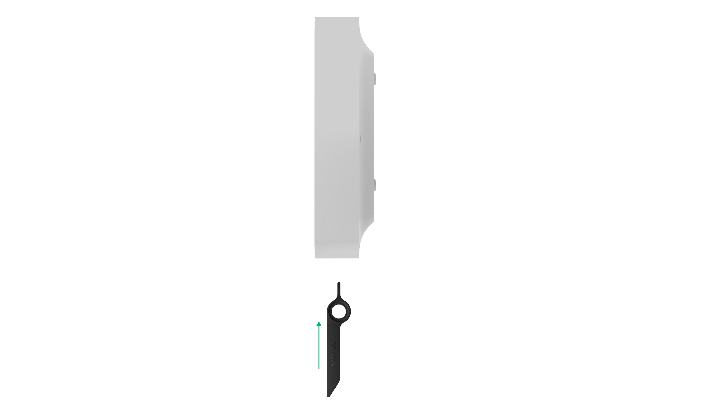
- Remove the SmartBracket mounting panel from the device. To do this, insert the special tool into the hole, and slide the mounting plate down.
- Carefully break out the necessary perforated part to output the cable from the rear side (top, bottom, or through the wall).
If you are not routing cables inside the wall, use the GlandBox wiring accessory with red cable glands (not included).
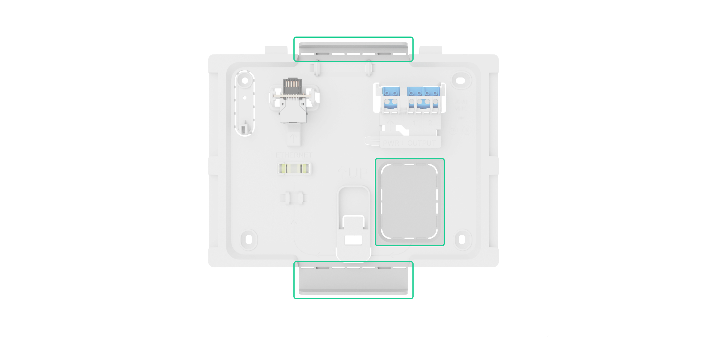
- Run the power, Ethernet, and optionally signal cables into the central unit enclosure.
- Secure the SmartBracket mounting panel to a vertical surface at the selected installation site using the bundled screws at all fixation points. One of them is in the perforated part above the tamper button — it is required for tamper alarm triggering in case of any attempt to detach the device.
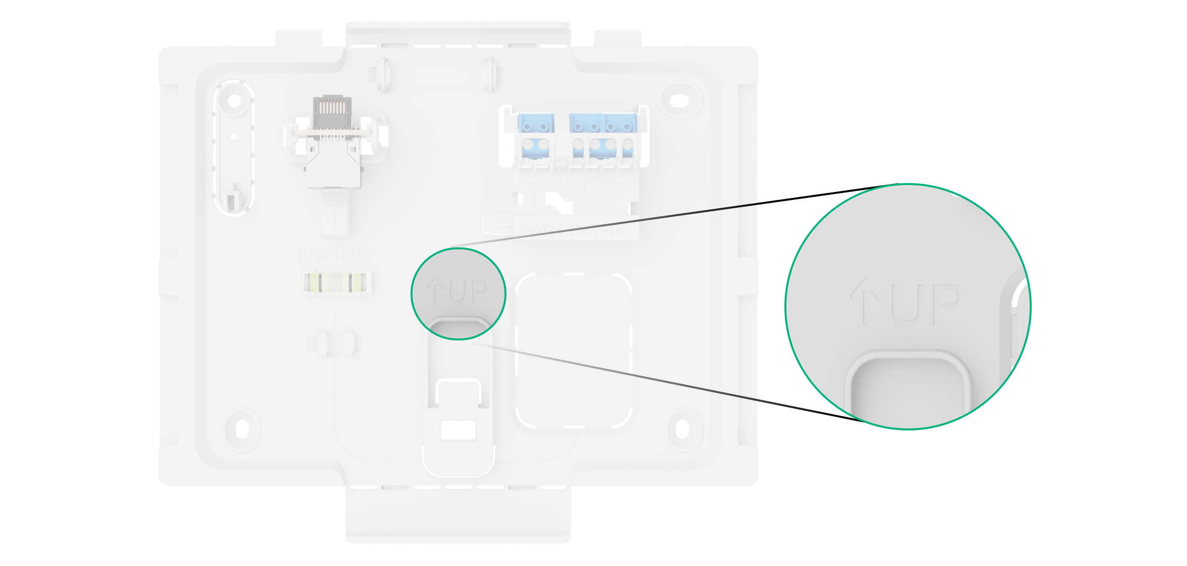
The UP key on SmartBracket marks the top of the device. Orient these markings when installing the central unit. Also use the bubble level to check the inclination angle of the mount during installation.
- Connect the Ethernet, external power cable, and optionally signal cables to the appropriate connector and terminals.
Selecting the cables for connecting to power supply and relay outputs, adhere to the rules and requirements of regulatory legal acts on electrical safety.
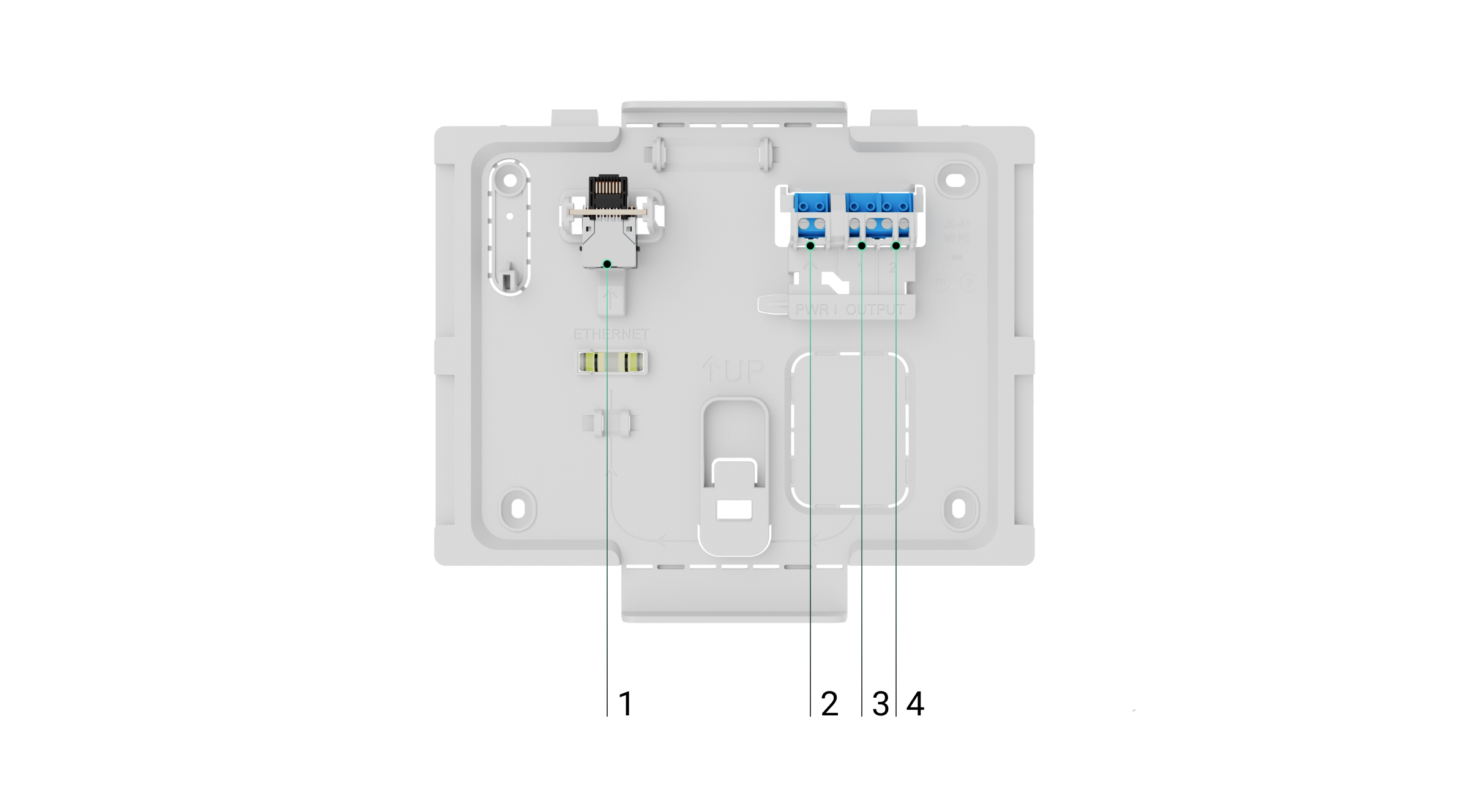
1 — Ethernet cable connector.
2 — terminals for connecting external power supply 110–240 V, 50/60 Hz.
3 — relay output for connecting the signal cable for sending events to the monitoring station in case of any fault in the system.
4 — relay output for connecting the signal cable for sending events to the monitoring station in case of fire alarm. - Install the internal battery.
Use only Type4 Internal Battery (24h) or Type4 Internal Battery (72h). We do not guarantee correct device operation with third-party batteries, and they can cause the central unit to fail.
- Install SIM cards:
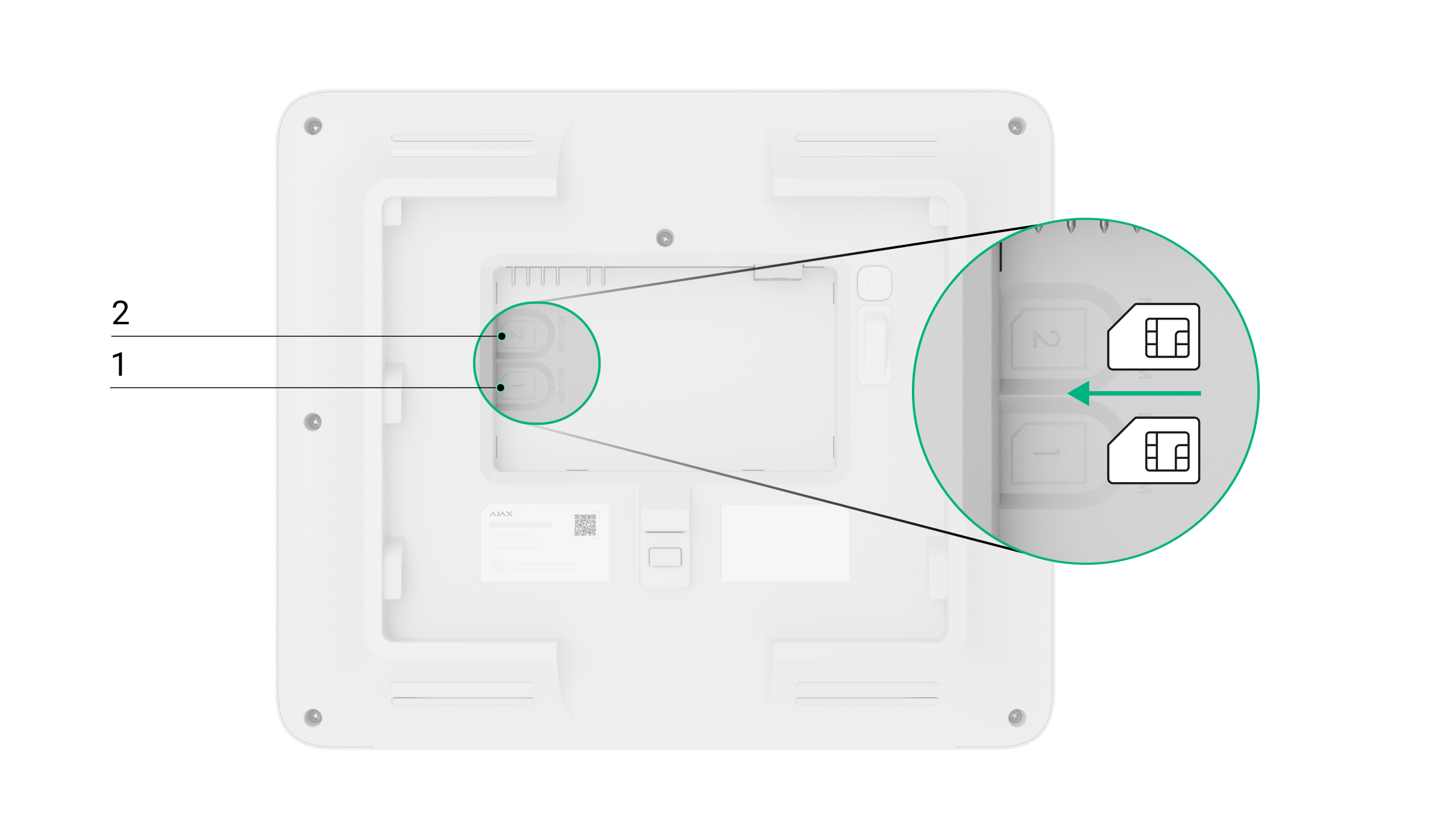
1 — the first micro SIM slot.
2 — the second micro SIM slot. - Add the central unit to a space.
- Place the turned on device on the SmartBracket mounting panel.
- Switch on the external power supply, if the power cable was de-energized previously.
- Check the status of the central unit in an Ajax app. If a tamper alarm is indicated, ensure that the mounting panel is closed tightly.
- Run the central unit indication test.
If Ethernet connection fails
If the Ethernet connection is not established, disable proxy and MAC address filtration and activate DHCP in the router settings. The central unit will automatically receive an IP address. After that, you can assign a static IP address to the central unit in the Ajax app.
If SIM connection fails
To connect to the cellular network, you need to install a micro SIM card with a PIN code request disabled and a sufficient amount of funds on the account to pay for services as per the operator’s tariff. To disable the PIN code request, insert the SIM card into the phone.
If the central unit fails to connect to the cellular network, use Ethernet to configure the network parameters: roaming, APN access point, user name, and password. To find out these parameters, contact the support service of your mobile operator.
Zone management
How to disable or enable Type4 devices
A user with access level 2 can disable Type4 devices in fire zones. Information that some devices are disabled is shown on the central unit Control tab, and in the Event center tab → Fault, test, or disablement tab.
To provide the device disablement or activation:
- Log in using an access code.
- Go to the Fire zones tab.
- Tap zone, where you want to disable/enable devices.
- If you want to disable a particular device, tap Open device list, and select the device. Tap Disable device or Enable device, choose its sensors or annunciation devices you want to enable/disable (e.g., heat sensor, VAD, or sounder).
- If you want to enable/disable all sensors or annunciation devices in a particular zone, tap Disable zone devices or Enable zone devices. Select sensors, sounders, and VADs you need to enable or disable.
- Tap Save.
A zone in which devices are partially or completely disabled will be marked correspondingly in the Fire zones tab.
The LED and audible fault indications related to Jeweller connection loss can be disabled on Type4 Fire Hub Jeweller for specific use cases, such as Type4 devices installed in vehicles that may temporarily leave the fire station and later return.
All devices added to the central unit are also available from the Devices ![]() tab.
tab.
How to run an alarm annunciation test
An admin, PRO, or user with access level 2 can run an alarm annunciation test of Type4 devices. The test allows checking the sound and visual alarm signals, and to ensure that fire alarm signals are clearly audible and visible within the premises. It runs for up to 10 minutes and can be stopped earlier if needed. Information that some devices are in test mode is shown on the central unit Control tab, and in the Event center → Fault, test, or disablement tab.
To run the test:
- Log in with your personal or access code, or apply Tag/Pass to the reader on the central unit front panel.
- Go to the Fire zones tab.
- Select zone, where you want to run the test.
- Tap Open device list, and select the device.
- Tap Alarm annunciation test.
- Choose annunciation devices you want to test.
- Tap Start test.
- To stop the test, repeat steps from 2 to 4, and tap Stop active test.
All devices added to the central unit are also available from the Devices ![]() tab.
tab.
How to run Zone test
Zone test is a special mode that allows installers to check fire detector operation in selected zones. In test mode, smoke detectors respond to test aerosols, such as Solo 332. During the test, installers can define which outputs, such as sounders, visual alarm devices (VADs), or I/O module relays, will be activated in each zone.
An admin or user with access level 2 can run Zone test from the central unit touch screen or via Ajax apps.
- Go to the Fire zones tab on the central unit touch screen.
- Select the required zone.
- Tap Run zone test.
- Select whether to activate outputs (sounders, VADs, and relays) during the test:
- Don’t activate outputs
- Activate only in tested zones
- Activate in all zones.
- If the Activate only in tested zones or Activate in all zones option is selected, choose the devices to be triggered by the test alarm:
- Sounders
- VADs
- Relays.
- Tap Start test.
To add another zone to the current test, select the required zone and tap Add to current zone test.
Maintenance
Check the functioning of Type4 Fire Hub Jeweller and connected devices on a regular basis. The optimal frequency of checks is once every three months. Clean the device enclosure from dust, cobwebs, and other contaminants as they emerge. Use a soft, dry cloth that is suitable for equipment care.
Do not use substances that contain alcohol, acetone, petrol, and other active solvents to clean the device.
Warranty
Warranty for the Limited Liability Company “Ajax Systems Manufacturing” products is valid for 2 years after the purchase.
If the device does not operate properly, we recommend contacting Ajax Technical Support first. In most cases, technical issues can be resolved remotely.
Contact Technical Support:
Manufactured by “AS Manufacturing” LLC
