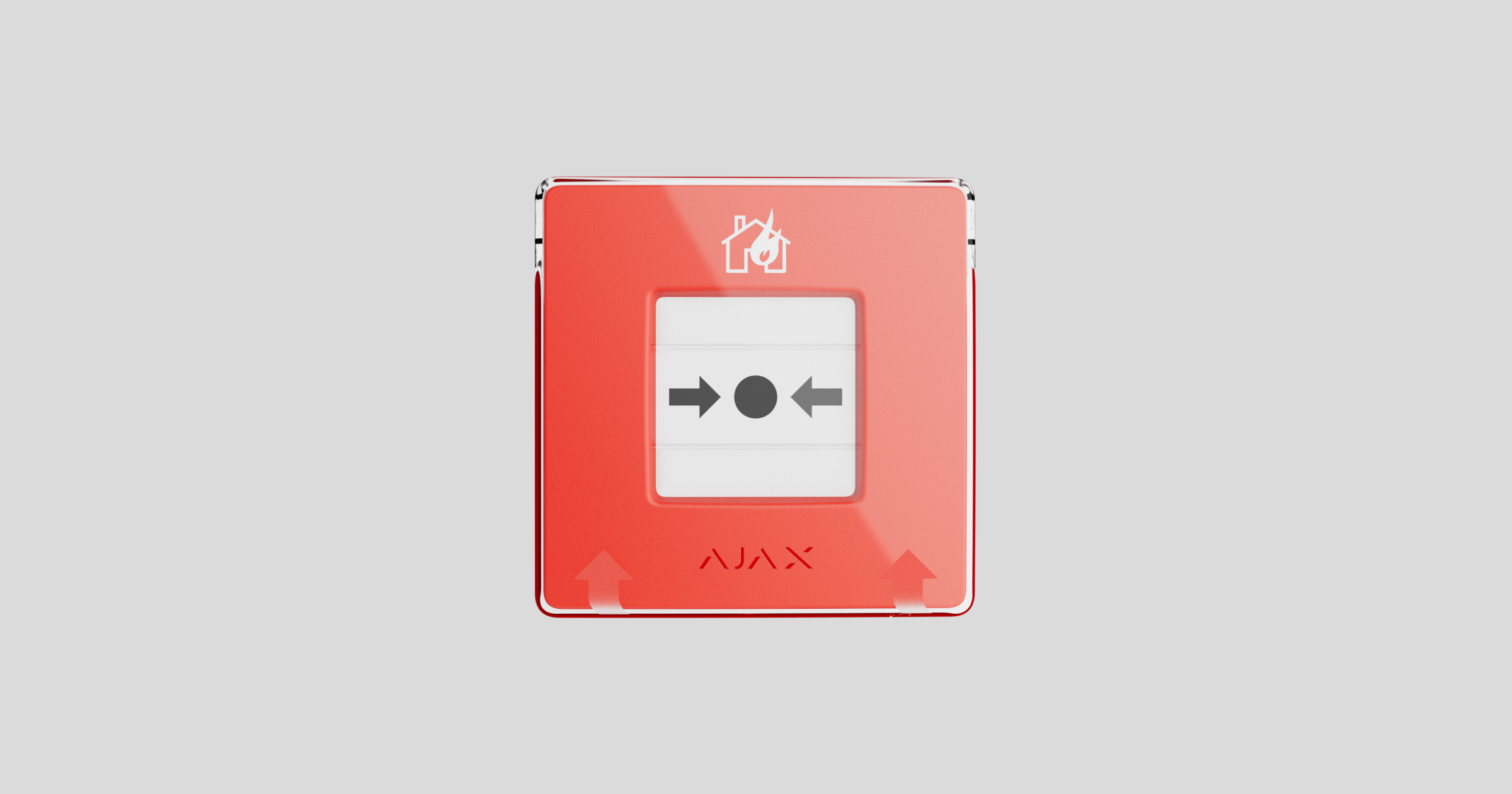
ManualCallPoint Jeweller is a wireless wall-mounted button for manual fire alarm activation. The device allows you to activate an alarm in case of an emergency. The button can be reset using a special tool (key) included in the kit. The device is designed for indoor installation only.
Unlike the resettable buttons, the default operating mode of ManualCallPoint (Red) Jeweller is Fire alarm. Learn more
To transmit alarms and events, ManualCallPoint Jeweller communicates with the hub or the control and indicating equipment (CIE) via the secure Jeweller protocol. The communication range is up to 1,700 meters without obstacles.
Functional elements
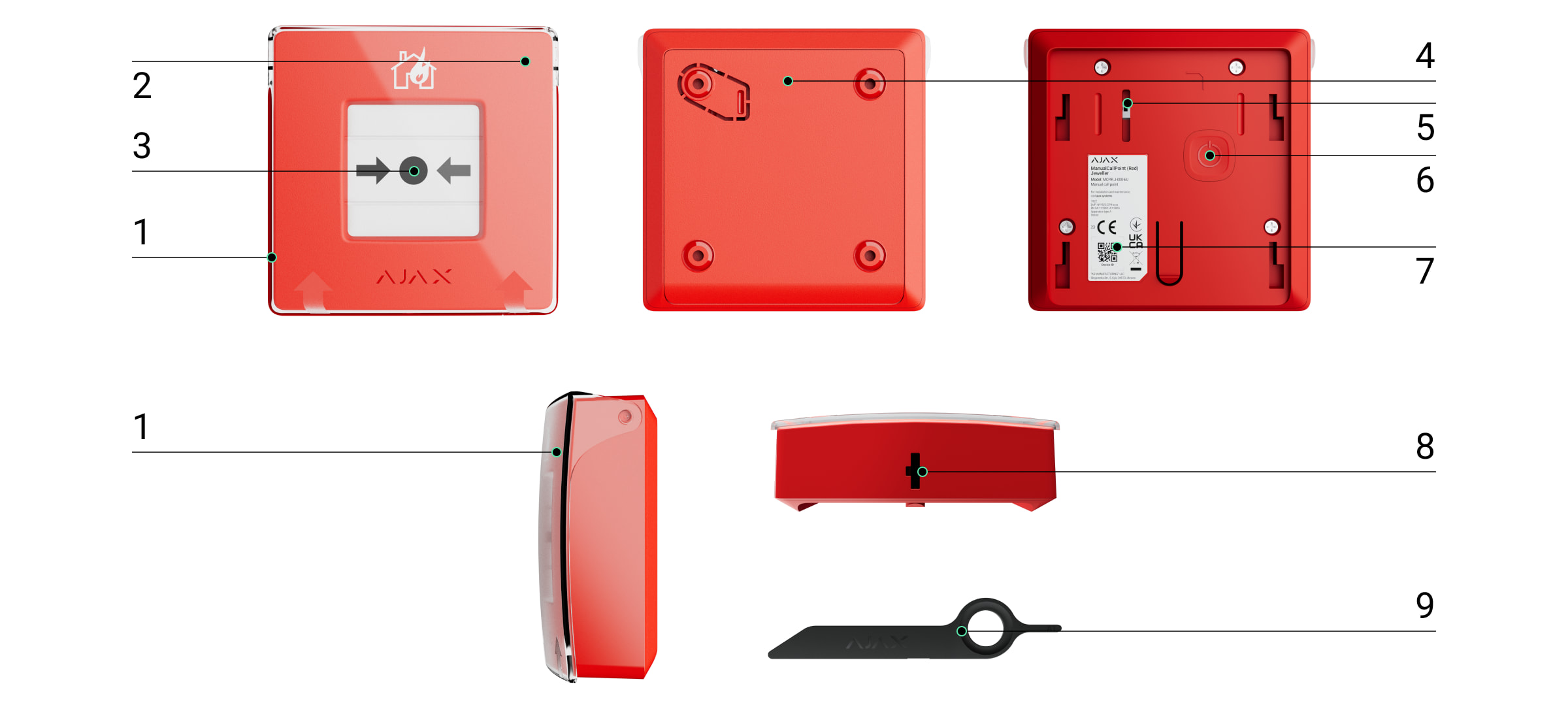
- Transparent protective lid.
- LED indicator.
- Resettable frangible element.
- SmartBracket mounting panel.
- Tamper button. Triggers when someone tries to detach the button from the surface or remove it from the mounting panel.
- Power button.
- QR code with the device ID for pairing the button with an Ajax hub or an Ajax CIE.
- Hole for the special tool.
- Special tool (key).
Compatible hubs, CIEs, and range extenders
ManualCallPoint Jeweller requires the Ajax hub or the Ajax CIE with an up-to-date OS Malevich version.
Operating principle
ManualCallPoint Jeweller enables alarm triggering in case of an emergency. Lift the transparent protective lid (if installed) and press the central part (resettable frangible element) to activate. This action moves the frangible element inward, raising the alarm. Two yellow stripes will appear at the top and bottom, indicating the device’s state.

ManualCallPoint Jeweller can be added to the Ajax hub or the Ajax CIE. The device’s operation in the system depends on this.
When it is added to the Ajax hub
By default, the system activates the built-in sirens of fire detectors when the interconnected fire alarm is enabled. An alarm signal is then transmitted to the central monitoring station (CMS). Users receive sound alarm notifications in the Ajax app. The system can be configured to send Critical Alerts that bypass “silent” or “do not disturb” phone settings.
The alarm duration on Ajax sirens depends on the time selected in the siren’s settings if the If fire alarm button is pressed feature is enabled in the Alert with siren section. When the Interconnected fire detectors alarm feature is enabled in hub’s settings, the alarm on the Ajax fire detectors with built-in sirens remains active until ManualCallPoint Jeweller is reset. To reset the device, insert the special bundled key into the corresponding hole.

After resetting, the button is ready to be reused.
The device features a transparent lid to prevent accidental presses during its installation and use. However, installing the lid is optional.
ManualCallPoint Jeweller operates in different modes: Fire alarm (by default), Auxiliary alarm, Panic button, Gas leak alarm, Malfunction alert, Water leak alarm, and Scenario trigger.
In all modes except Scenario trigger, the button raises an alarm regardless of the security mode and activates alarm scenarios involving this device. The system also transmits an alarm signal to the CMS and users in the app. The former is optional and can be configured in the button settings.
In the Scenario trigger mode, ManualCallPoint Jeweller allows you to control one or more automation devices by pressing the button.
To bind an automation device action to the ManualCallPoint Jeweller press, follow these steps:
- Open the Ajax app and go to the Devices
 tab.
tab. - Select ManualCallPoint Jeweller in the list of devices and go to the Settings by clicking the gear icon
 .
. - Select the mode Scenario trigger in the Operating mode section.
- Go to the Scenarios menu. Click Create scenario if you are creating a scenario for the first time, or Add scenario, if scenarios have already been created in the system.
- Select the automation device to execute the action.
- Enter the Scenario name and specify the Device action to be executed by pressing ManualCallPoint Jeweller:
- Switch on;
- Switch off.
- If you’ve selected multiple devices, specify which of them will trigger the scenario: any from the list or all selected devices during the set time.

The Device action setting is unavailable when configuring a scenario for automation devices operating in pulse mode. When the scenario runs, these devices will close/open the contacts for a set time. You can adjust the operating mode and pulse duration in the automation device settings.
- Click Save.The new scenario will now appear in the device scenarios list.
When it is added to the Ajax CIE
Ajax devices from the EN54 Line connected to the CIE are assigned to one of 40 Fire zones. When a fire is detected in any zone or ManualCallPoint Jeweller is pressed, all Ajax EN54 sounders and VADs across the facility raise an alarm, and the EN54 I/O Module (2X2) Jeweller relays are activated.
ManualCallPoint Jeweller operates in different modes: Fire alarm (by default), Evacuation, Auxiliary alarm, Panic button, Gas leak alarm, Fault alert, Water leak alarm, and Custom action.
In all modes except Custom action, the button raises an alarm regardless of the security mode and activates alarm scenarios involving this device. The system also transmits an alarm signal to the CMS and users in the app. The former is optional and can be configured in the button settings.
Sending events to the monitoring station
The Ajax system can transmit alarms to both PRO Desktop monitoring app and the CMS in the formats of SurGard (Contact ID), SIA (DC-09) (SIA-DCS), ADEMCO 685, and other protocols.
ManualCallPoint Jeweller can transmit the following events:
- Fire alarm / recovery.
- Panic button alarm / recovery.
- Auxiliary alarm / recovery.
- Gas leak alarm / recovery.
- Malfunction or fault alarm / recovery.
- Water leak alarm / recovery.
- Scenario trigger / custom action.
- Tamper alarm/recovery.
- Loss/restoration of connection with the hub or the CIE.
- Permanent deactivation/activation of the button.
The system allows disabling fault indication and notifications of Jeweller connection loss for EN54 devices used in mobile environments, such as fire engines.
How to disable Jeweller connection loss notifications for EN54 devices
When an alarm is received, the operator at the security company’s CMS knows what happened and precisely where to dispatch a rapid response team. The addressability of Ajax devices allows sending events to PRO Desktop or the CMS, including the device type, its name, virtual room, security group or fire zone and location description. Note that the list of transmitted parameters may vary depending on the CMS type and the selected communication protocol for it.
The ID and the loop (zone) number of the device can be found in its states in the Ajax app.
Adding to the system
ManualCallPoint Jeweller is incompatible with Hub (2G) Jeweller, third-party security central panels, or ocBridge Plus and uartBridge integration modules.
To connect ManualCallPoint Jeweller to the hub or the CIE, the device must be located at the same secured facility as the system (within the hub’s or the CIE’s radio network range).
When using a radio signal range extender, first add ManualCallPoint Jeweller to the hub or the CIE, then connect it to the range extender in its settings. The EN54 Fire ReX Jeweller range extender, compatible with the CIE, will be available later.
The hub or the CIE and the device operating at different radio frequencies are incompatible. The radio-frequency range of the device may vary by region. We recommend purchasing and using Ajax devices in the same region. You can verify the range of operating radio frequencies with the technical support service.
Before adding a device
- Install the Ajax app.
- Log in to your account or create a new one.
- Select a space or create a new one.
- Add at least one virtual room.
- Add a compatible hub or CIE to the space. Ensure the hub or the CIE is switched on and has internet access via Ethernet, Wi-Fi, and/or mobile network.
- Ensure the space is disarmed, and the hub or the CIE is not starting an update by checking statuses in the Ajax app.
Only a PRO or a space admin with the rights to configure the system can add a device to the hub or the CIE.
Connecting to the hub or the CIE.
- Open an Ajax app. Select a space to which you want to add the device.
- Go to the Devices tab and tape Add device.
- Scan the QR code or enter the device ID manually. A QR code with the ID is placed on the device enclosure under the SmartBracket mounting panel. Also, it is duplicated on the device packaging.
- Assign a name to the device.
- Select a virtual room.
- If ManualCallPoint Jeweller connects to the hub, select a security group (if Group mode is enabled). If ManualCallPoint Jeweller connects to the CIE, select a fire zone and specify the device location in the Location field.
- Select Add device, and the countdown will begin.
- Switch on the device by holding the power button.
- Once the device is added, the LED will flash once.
When connecting ManualCallPoint Jeweller via the radio signal range extender, the button won’t automatically switch between the radio networks of the range extender and the hub. However, you can manually assign ManualCallPoint Jeweller to another hub or range extender in the app.
If you’ve reached the maximum number of devices the hub or the CIE can support (depending on the model), you’ll receive a notification when attempting to add another device.
Once connected to the hub or the CIE, the button will appear in the list of its devices in the Ajax app.
ManualCallPoint Jeweller works with one hub or CIE. When connected to a new hub or CIE, the device stops sending events to the old one. Adding the button to a new hub or CIE does not automatically remove it from the device list of the old one. This must be done through the Ajax app.
Malfunctions
When a malfunction is detected, the Ajax app displays a malfunction counter on the device icon. All malfunctions are indicated in the device’s states. Fields with malfunctions will be highlighted in red.
A malfunction is displayed if:
- no connection with the hub (or the CIE) or radio signal range extender via Jeweller;
- the button battery is low.
An admin or a user with access level 2 can disable the notifications of Jeweller connection loss. The Deactivate notifications feature allows disabling malfunction indication and notifications of Jeweller connection loss for EN54 devices used in mobile environments, such as fire engines.
Icons
The icons in the app display some ManualCallPoint Jeweller states. To access them:
| Icon | Value |
|
Jeweller signal strength displays the signal strength between the hub or the CIE and the button. The recommended value is 2–3 bars when ManualCallPoint Jeweller is added to the hub, and 3 bars when the device is added to the CIE. |
|
|
Battery charge level of the button. |
|
| The button operates via a radio signal range extender. | |
| The button test is in progress. | |
| The button has a fault. The list of faults is available in the device states. | |
| The button is pressed. | |
|
The button is permanently deactivated. The icon may be displayed if ManualCallPoint Jeweller is added to the hub. |
|
|
The button has tamper alarms permanently deactivated. The icon may be displayed if ManualCallPoint Jeweller is added to the hub. |
|
| The button is disabled. The icon may be displayed if ManualCallPoint Jeweller is added to the CIE. | |
| The device has lost connection with the hub (the CIE) or the hub (the CIE) has lost connection with the Ajax Cloud server. | |
|
The device has not been transferred to the new hub or CIE. |
States
The states include information about the device and its operating parameters. You can find the states of ManualCallPoint Jeweller in Ajax apps:
- Go to the Devices tab.
- Select ManualCallPoint Jeweller from the list.
| Parameter | Value |
| Alarm |
The button has been pressed in Fire alarm or Evacuation mode. The field is displayed only if a fire is detected. |
| Data import | Displays the error when transferring data to the new hub or CIE:
|
| Fault |
Click the The field appears only if a fault is detected. A fault is a critical interferer for fire alarm system operation according to the EN 54 standard. |
| Malfunction |
Click the The field appears only if a malfunction is detected. A malfunction is not a critical interferer for fire alarm system operation according to the EN 54 standard. |
| Disabled |
The device is disabled. It does not respond to the alarm or notify users and the monitoring station. Tapping on The field is displayed only if the device is disabled. |
| Test |
The device test is in progress. The field is displayed only if ManualCallPoint Jeweller is added to the CIE. |
| Temperature |
Temperature of the device. It is measured on the processor and changes depending on the ambient temperature. You can configure a scenario by temperature to control automation devices. |
| Jeweller signal strength |
Signal strength between the hub (the CIE) or range extender and the button on the Jeweller channel. The recommended value is 2–3 bars when ManualCallPoint Jeweller is added to the hub, and 3 bars when added to the CIE. |
| Connection via Jeweller | Connection status on the Jeweller channel between the device and the hub (the CIE) or the range extender:
|
| ReX | Connection status between the device and the radio signal range extender. |
| Battery charge | Battery charge level of the device. Two states available:
|
| Lid | The status of the button tamper that responds to detachment or opening of the device enclosure:
|
| Current state | If the device is operating in Fire alarm, Evacuation, Auxiliary alarm, Panic button, Gas leak alarm, Malfunction alert or Water leak alarm modes:
If the device is operating in the Scenario trigger or Custom action mode:
|
| Operating mode | When ManualCallPoint Jeweller is added to the hub, the button operating modes are:
When ManualCallPoint Jeweller is added to the CIE, the button operating modes are:
|
| Local Alarm Only | When enabled, an alarm from this device will not send a signal to the central monitoring station. However, alarms from interconnected fire detectors are activated regardless of the state of this toggle. |
| Permanent deactivation | Status of the device’s permanent deactivation setting:
The field is displayed only if ManualCallPoint Jeweller is added to the hub. |
| Fire zone |
Number and name of the fire zone to which the device is assigned. The field is displayed only if ManualCallPoint Jeweller is added to the CIE. |
| Room | Name of the room to which the device is assigned. |
| Location |
Detailed description of the device location. The field is displayed only if ManualCallPoint Jeweller is added to the CIE. |
| Firmware | ManualCallPoint Jeweller firmware version. |
| Device ID | Device ID. Also available on the QR code on both the button enclosure and its packaging. |
| Device No. | Number of the device loop (zone). |
Settings
To change ManualCallPoint Jeweller settings, in the Ajax app:
- Go to the Devices tab.
- Select ManualCallPoint Jeweller from the list.
- Go to Settings .
- Set the required parameters.
- Click Back to save the new settings.
| Parameter | Value |
| Name | Name of the device. Can be changed. |
| Fire zone |
Selecting the fire zone to which ManualCallPoint Jeweller is assigned. The fire zone is displayed in the text of SMS and notifications in the event feed. The setting is available only if ManualCallPoint Jeweller is added to the CIE. |
| Room | Selecting the virtual room to which ManualCallPoint Jeweller is assigned. |
| Location |
Detailed description of the device location. It is displayed next to the room name in the event feed notifications. The location field can contain up to 24 Latin or Cyrillic characters. The setting is available only if ManualCallPoint Jeweller is added to the CIE. |
| Operating mode | Selecting the button operating mode:
After pressing the button in all modes except Scenario trigger or Custom action, an alarm is sent to the Ajax app and CMS, and scenarios in which the button is involved are activated. |
| Local Alarm Only | When enabled, an alarm from this device will not send a signal to the central monitoring station. However, alarms from interconnected fire detectors are activated regardless of the state of this toggle. |
| Alert with siren | |
| If MCP button is pressed |
When enabled, pressing the button will activate any sirens that have been added to the system. The setting is available only if ManualCallPoint Jeweller is added to the hub. |
| Scenarios |
Opens the menu to create and configure the automation scenarios. The setting is available only if ManualCallPoint Jeweller is added to the hub. |
| Jeweller signal strength test |
Allows the user to determine signal strength and stability in the intended installation place. |
| User guide | Opens ManualCallPoint Jeweller user manual. |
| Permanent deactivation |
Allows the user to deactivate the device without removing it from the system. Three options are available:
The setting is available only if ManualCallPoint Jeweller is added to the hub. |
| Device disablement |
The option allows for deactivating the device or its specific functions. The device remains within the system, but will no longer raise an alarm. The setting is available only if ManualCallPoint Jeweller is added to the CIE. |
| Delete device | Disconnects ManualCallPoint Jeweller from the hub or the CIE and deletes its settings. |
Indication
ManualCallPoint Jeweller indicates its state with an LED indication in the upper right corner of the device.
| Category | Indication | Event |
| Alarm. | The LED flashes continuously. | The LED flashes as long as the frangible element is pressed. |
| Tamper alarm. | The LED flashes once. | The button is removed from the SmartBracket mounting panel. |
| Turning on the button. | The LED flashes once. | To turn on the button, hold the power button for 1 second. |
| Turning off the button. | The LED flashes three times. | To turn off the button, hold the power button for 2 seconds. |
| Malfunction detected. | The LED flashes continuously. | |
| Low battery level. | The LED flashes once per minute. | |
| Battery completely drained. | The LED flashes rapidly for a short time. |
Functionality testing
The Ajax system offers several types of tests to assist in selecting the correct installation location for the devices. Tests do not start immediately. However, the waiting time does not exceed the duration of one “hub—device” polling interval. You can check and configure the polling interval in the hub or CIE settings (Hub (CIE) → Settings ![]() → Jeweller or Jeweller/Fibra).
→ Jeweller or Jeweller/Fibra).
To run a test, in the Ajax app:
- Select the required space.
- Go to the Devices tab.
- Select ManualCallPoint Jeweller from the list.
- Go to Settings .
- Select Jeweller signal strength test.
- Run the test.
Device placement
The device is designed for indoor use only.
When choosing a location for ManualCallPoint Jeweller, consider the parameters that affect its operation:
- Jeweller signal strength;
- the distance between the device and the hub (the CIE) or radio signal range extender;
- the presence of barriers that might hinder radio signal transmission between devices, such as walls, interfloor ceilings, or large objects located in the premises.
ManualCallPoint Jeweller should be located on escape routes, particularly at all storey exits and all exits to open air leading to an ultimate place of safety (even if these exits are not labeled as fire exits).
ManualCallPoint Jeweller should be fixed at a height of 1.4 m above the finished floor level, in easily accessible, well-illuminated, and conspicuous positions free from potential obstruction. They should be set against a contrasting background for easy recognition. A lower mounting height is acceptable if there’s a high likelihood that the first person to raise a fire alarm will be a wheelchair user.
Consider the placement recommendations when designing the security system project for the facility. The security system should be designed and installed by professionals. A list of recommended partners is available here.
Signal strength
The Jeweller signal strength is determined by the number of undelivered or corrupted data packages over a certain period of time. The icon ![]() on the Devices
on the Devices ![]() tab indicates the signal strength:
tab indicates the signal strength:
- three bars — excellent signal strength;
- two bars — good signal strength;
- one bar — low signal strength, stable operation is not guaranteed;
- crossed out icon — no signal.
Run the Jeweller signal strength test before final installation. The test checks the signal strength at the device’s maximum transmission power. To comply with the EN 54 requirements, the signal strength between the device and the CIE must be three bars.
If the test shows the signal strength of one or zero bars, we do not guarantee stable operation of the device. Consider relocating the device, as adjusting its position even by 20 cm can significantly improve the signal strength. If the signal remains poor or unstable after relocation, consider using a radio signal range extender.
How not to install the button
- Outdoors, as it can lead to false alarms and device failure.
- Inside premises with temperature and humidity outside the permissible limits, as this can damage the device.
- Closer than 1 meter to the hub (the CIE) or radio signal range extender to prevent connection loss with the hub.
- In areas with low or unstable signal strength, this may result in connection loss with the hub or the CIE.
- In hard-to-reach or poorly-lit places.
Installation
Before installing ManualCallPoint Jeweller, ensure that you have selected the optimal location that complies with the requirements of this manual.
To mount the button:
- Remove the SmartBracket mounting panel from the button. To do this, insert a special tool into the hole and slide the mounting plate down.

- Fix the SmartBracket mounting panel using double-sided tape or other temporary fasteners. Place the mounting panel on a vertical surface at a height of 1.4 meters.

Use double-sided tape only for temporary attachment. If the device is only attached with tape, it may detach from the surface at any time, and the tamper will not trigger if the device is removed.
- Place the button, with the transparent lid closed, onto the SmartBracket mounting panel. The device’s LED indicator will flash, signaling the tamper on the button is closed.
- Run the Jeweller signal strength test. Aim for a signal strength of two or three bars.
- Remove the button from SmartBracket.
- Securely attach the SmartBracket mounting panel using the bundled screws at all fixation points. One fixation point is in the perforated part of the mounting panel, above the tamper. If using alternative fasteners, ensure they do not damage or deform the mounting panel.
- Reattach the button onto the SmartBracket mounting panel.
The special tool has a hole in its enclosure, making it handy to carry. Those responsible for fire safety might find it convenient to attach the special tool to their keychain.
Actions to take in case of a fire alarm
NEVER IGNORE THE ALARM! Always assume the alarm is real, and evacuate from the premises immediately, even if you have doubts about the cause of the alarm signal.
- Don’t open the doors if you feel heat or smoke behind them. Check other exits and use an alternative escape route. Always close doors behind you when leaving.
If heavy smoke enters a room, stay close to the floor and crawl out. If possible, breathe through a wet cloth or try to hold your breath. Be aware that smoke inhalation causes more death than fire.
- Evacuate as quickly as you can, don’t panic. Save time, don’t pack your things. Arrange a meeting place outside for everyone in the building. Ensure everyone has evacuated safely.
- Call the fire department immediately, or ask someone nearby. Remember, even small fires can spread rapidly; call the fire department even if the alarm is automatically transmitted to a monitoring station.
NEVER come back to the house on fire.
Maintenance
Clean the device’s enclosure to remove dust, cobwebs, and other contaminants as they emerge. Use soft, dry wipes suitable for cleaning electronic equipment. Avoid using substances that contain alcohol, acetone, petrol, and other active solvents when cleaning the device.
The pre-installed battery lasts up to 7 years with typical use (one press of one minute per week). Using it more often may reduce its lifespan. You can monitor the battery level at any time in the Ajax app.
Technical specifications
Warranty
Warranty for the Limited Liability Company “Ajax Systems Manufacturing” products is valid for 2 years after the date of purchase.
If you encounter any issues with the device’s functionality, we recommend contacting Ajax Technical Support first. In most cases, technical issues can be resolved remotely.
Contact Technical Support:
Manufactured by “AS Manufacturing” LLC
