
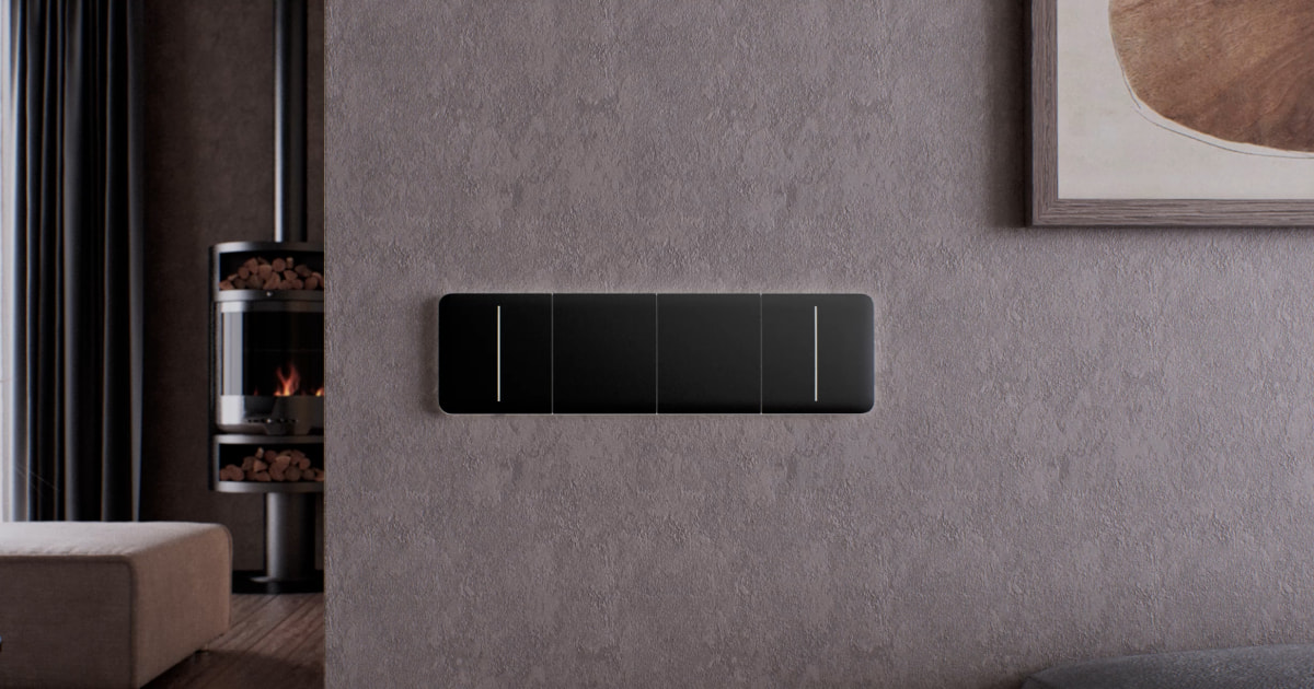
LightSwitch Jeweller is a smart touch light switch for indoor installation. LightSwitch can replace any mechanical or touch switch: the product line includes one-gang, two-gang, and two-way versions. Devices can be combined as a set with Ajax smart switches and/or outlets and installed horizontally or vertically into Frame side by side.
Use the online Ajax switches and outlets configurator to assemble your custom set. Combine devices into a frame, pick the color, and download your configuration as PDF.
LightSwitch is installed without changing the electrical wiring of the object. The device does not require a neutral wire and works only from the power phase. The switch features a standard European form factor (55).
LightSwitch operates as part of the Ajax system and communicates with the hub via the Jeweller secure radio communication protocol. The communication range is up to 1,100 meters in an open space.
The list of compatible hubs and range extenders is available here.
Design
LightSwitch is a prefabricated smart light switch. All switch elements are purchased separately. Elements are connected mechanically without the use of tools. There are two LightSwitch formats in the Ajax product line: single and combined. Combined switches can be horizontal and vertical.
Single switch
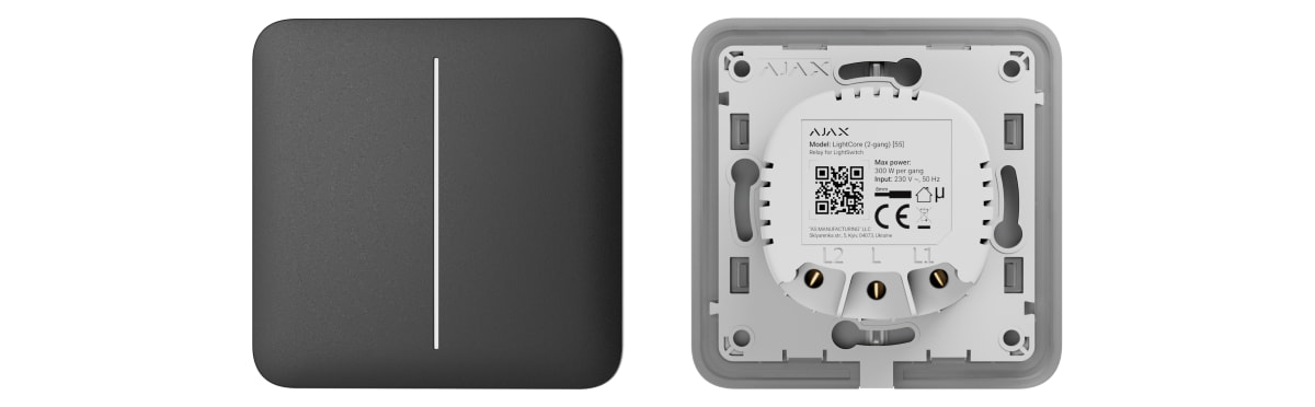
A single LightSwitch consists of two elements: a LightCore relay and a SoloButton touch-sensitive panel.
- LightCore (1-gang) — relay for a 1-gang switch.
- LightCore (2-gang) — relay for a 2-gang switch.
- LightCore (2-way) — relay for a 2-way switch.
- SoloButton (1-gang) — touch-sensitive panel for a 1-gang or 2-way switch.
- SoloButton (2-gang) — touch-sensitive panel for a 2-gang switch.
Combined switch
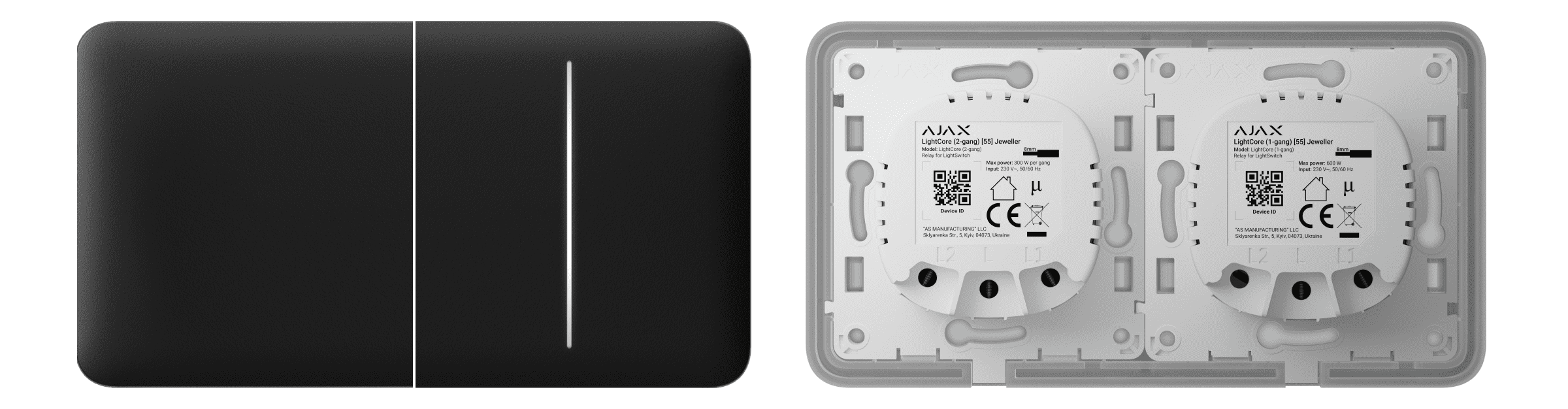
A combined switch consists of several LightCore relays and touch-sensitive panels installed in one frame with the appropriate number of seats.
- LightCore (1-gang) — relay for a 1-gang switch.
- LightCore (1-gang) vertical — relay for a vertical 1-gang switch.
- LightCore (2-gang) — relay for a 2-gang switch.
- LightCore (2-gang) vertical — relay for a vertical 2-gang switch.
- LightCore (2-way) — relay for a 2-way switch.
- LightCore (2-way) vertical — relay for a vertical 2-way switch.
- Frame (2 seats) — frame for two devices.
- Frame (2 seats) vertical — vertical frame for two devices.
- Frame (3 seats) — frame for three devices.
- Frame (3 seats) vertical — vertical frame for three devices.
- Frame (4 seats) — frame for four devices.
- Frame (4 seats) vertical — vertical frame for four devices.
- Frame (5 seats) — frame for five devices.
- Frame (5 seats) vertical — vertical frame for five devices.
- CenterButton (1-gang) — central touch-sensitive panel for a 1-gang or 2-way switch.
- CenterButton (1-gang) vertical — central touch-sensitive panel for a vertical 1-gang or 2-way switch.
- CenterButton (2-gang) — central touch-sensitive panel for a 2-gang switch.
- CenterButton (2-gang) vertical — central touch-sensitive panel for a vertical 2-gang switch.
- SideButton (1-gang) — side touch-sensitive panel for a 1-gang or 2-way switch.
- SideButton (1-gang) vertical — side touch-sensitive panel for a vertical 1-gang or 2-way switch.
- SideButton (2-gang) — side touch-sensitive panel for a 2-gang switch.
- SideButton (2-gang) vertical — side touch-sensitive panel for a vertical 2-gang switch.
Side touch-sensitive panels are installed on the right and left or on the top and bottom sides of the frame, while central touch-sensitive panels are installed in the center. For example, two side panels and one central panel should be used for three switches in one frame.
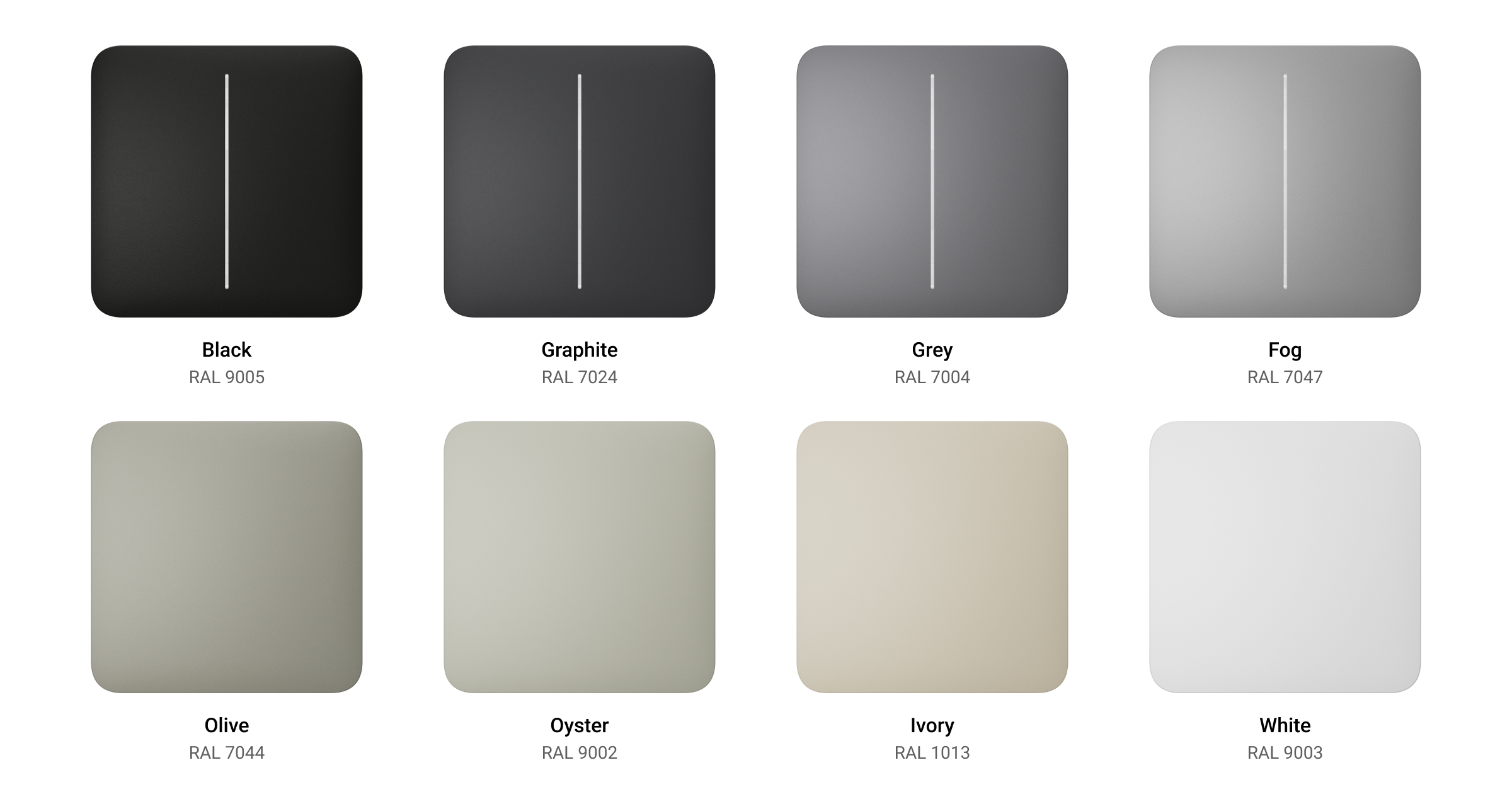
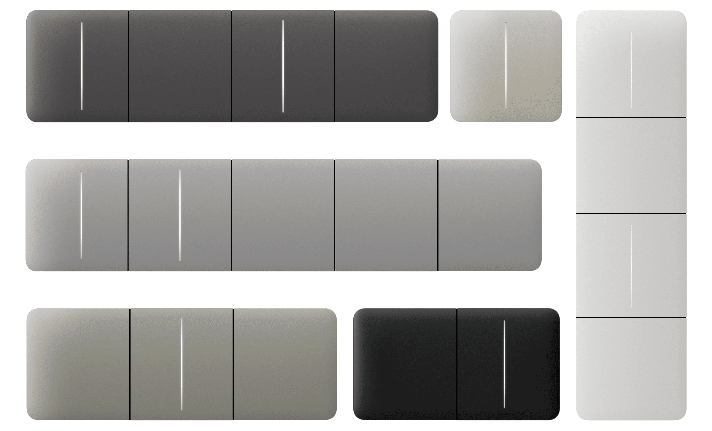
Colors
The product line includes 8 colors of touch-sensitive panels: White, Fog, Grey, Graphite, Ivory, Oyster, Olive, and Black.
The RAL colors below are as close as an approximation of the actual color. However, they may slightly differ, so please only use them as a guide to the color choice.
In the switch settings in Ajax apps, the color of LightSwitch can be selected. The color in the app does not necessarily have to match the color of the installed panel.
A PRO or user with admin rights can change the panel color anytime. For example, if the installer has replaced the touch-sensitive panel or a user wishes to set different color for the switches in the app to distinguish them.
Functional elements
Relay

- Device QR code and ID (serial number). It is used to add the switch to the Ajax system.
- Terminal for connecting the power phase wire.
- Terminal for connecting the power wire of a lighting device or another load. For example, a hood.

- Device QR code and ID (serial number). It is used to add the switch to the Ajax system.
- Terminal for connecting the power phase wire.
- Terminal for connecting the power wire of a lighting device or another load. For example, a hood.

- Device QR code and ID (serial number). It is used to add the switch to the Ajax system.
- Terminal for connecting the power phase wire.
- Terminal for connecting the power wire of the first lighting device or another load. For example, a hood.
- Terminal for connecting the power wire of the second lighting device or another load. For example, a hood.
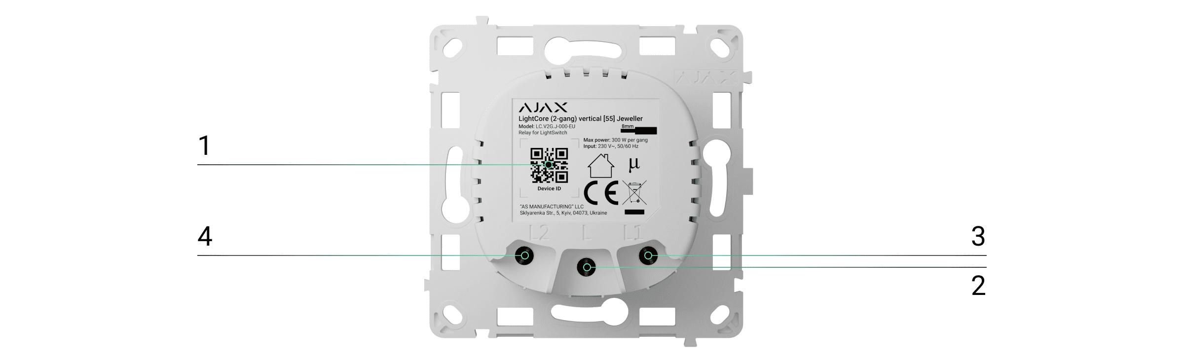

- Device QR code and ID (serial number). It is used to add the switch to the Ajax system.
- Terminal for connecting the power phase wire.
- The first terminal (L1) for connecting to the 2-way or crossover light switch.
- The second terminal (L2) for connecting to the 2-way or crossover light switch.
Touch-sensitive panels
Ensure that the sticker shown in the image below has been removed from the touch-sensitive panel before installing it on LightCore. This is necessary for correct LED indication of the device.


- Touch-sensitive panel button.

- The first button of the touch-sensitive panel.
- The second button of the touch-sensitive panel.

- Touch-sensitive panel button.

- Touch-sensitive panel button.

- The first button of the touch-sensitive panel.
- The second button of the touch-sensitive panel.

- The first button of the touch-sensitive panel.
- The second button of the touch-sensitive panel.

- Touch-sensitive panel button.

- Touch-sensitive panel button.

- The first button of the touch-sensitive panel.
- The second button of the touch-sensitive panel.

- The first button of the touch-sensitive panel.
- The second button of the touch-sensitive panel.
Frames

- Frame for two devices.
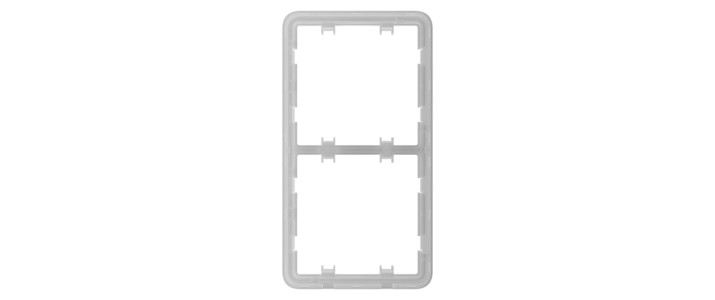
- Vertical frame for two devices.
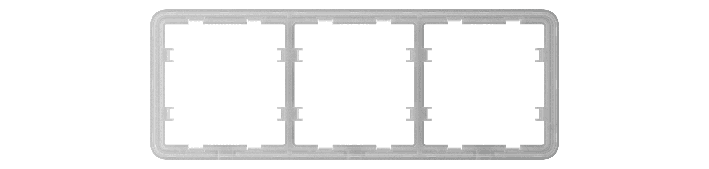
- Frame for three devices.
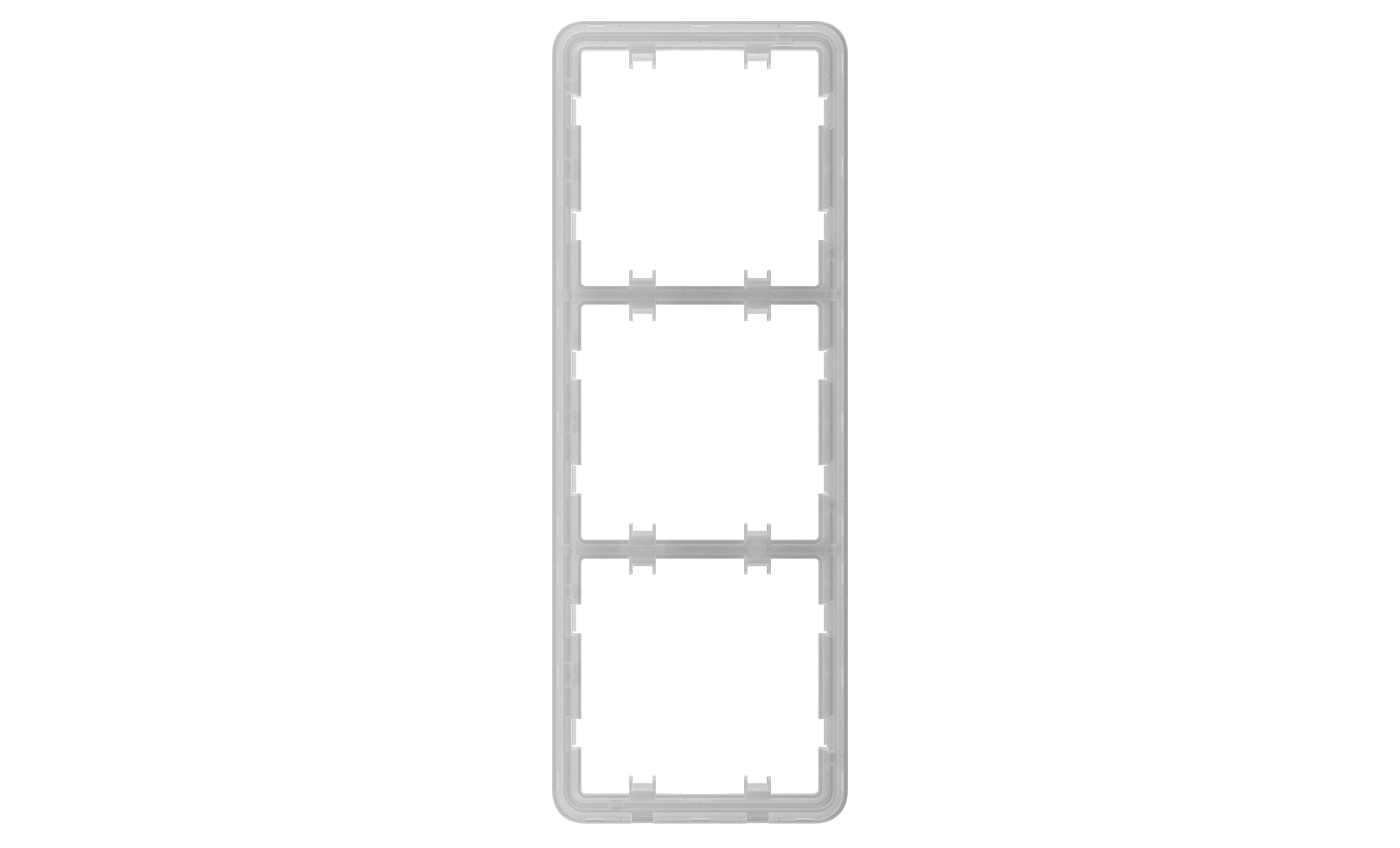
- Vertical frame for three devices.
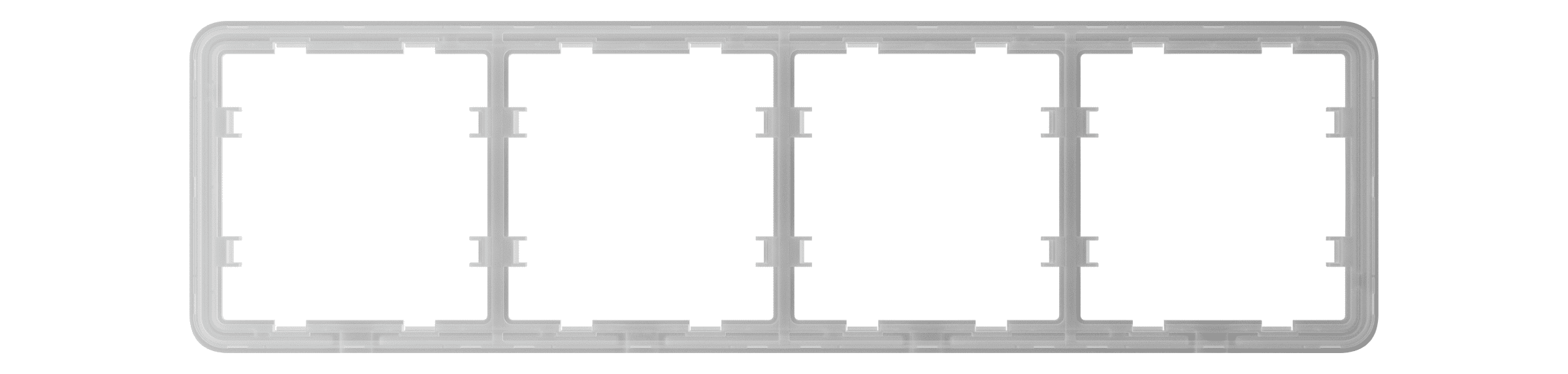
- Frame for four devices.
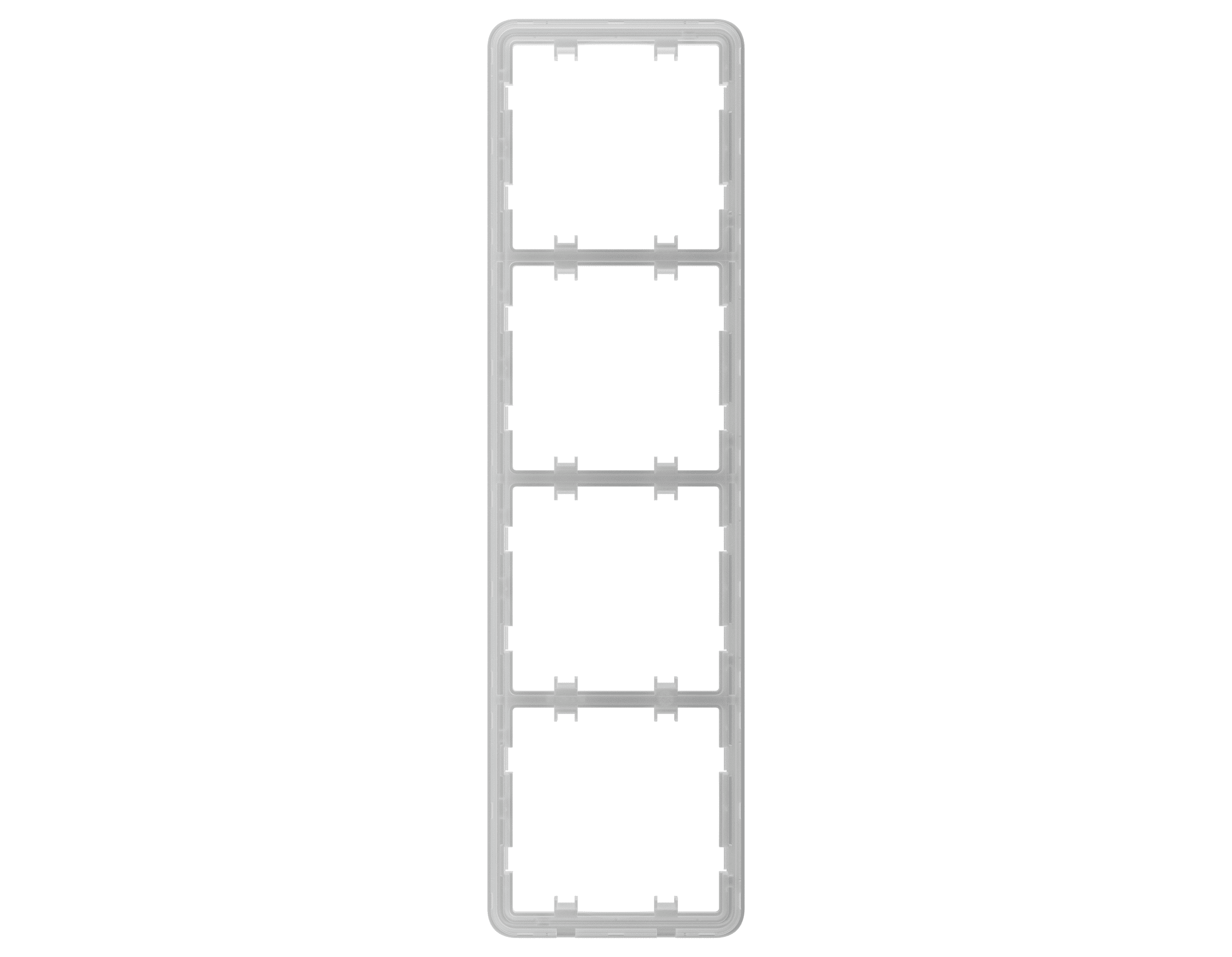
- Vertical frame for four devices.
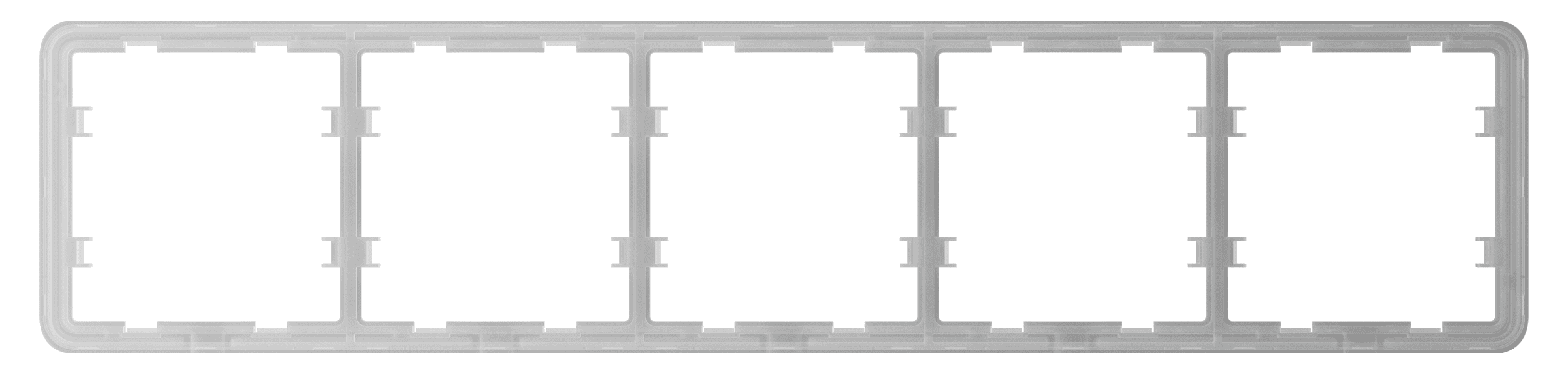
- Frame for five devices.
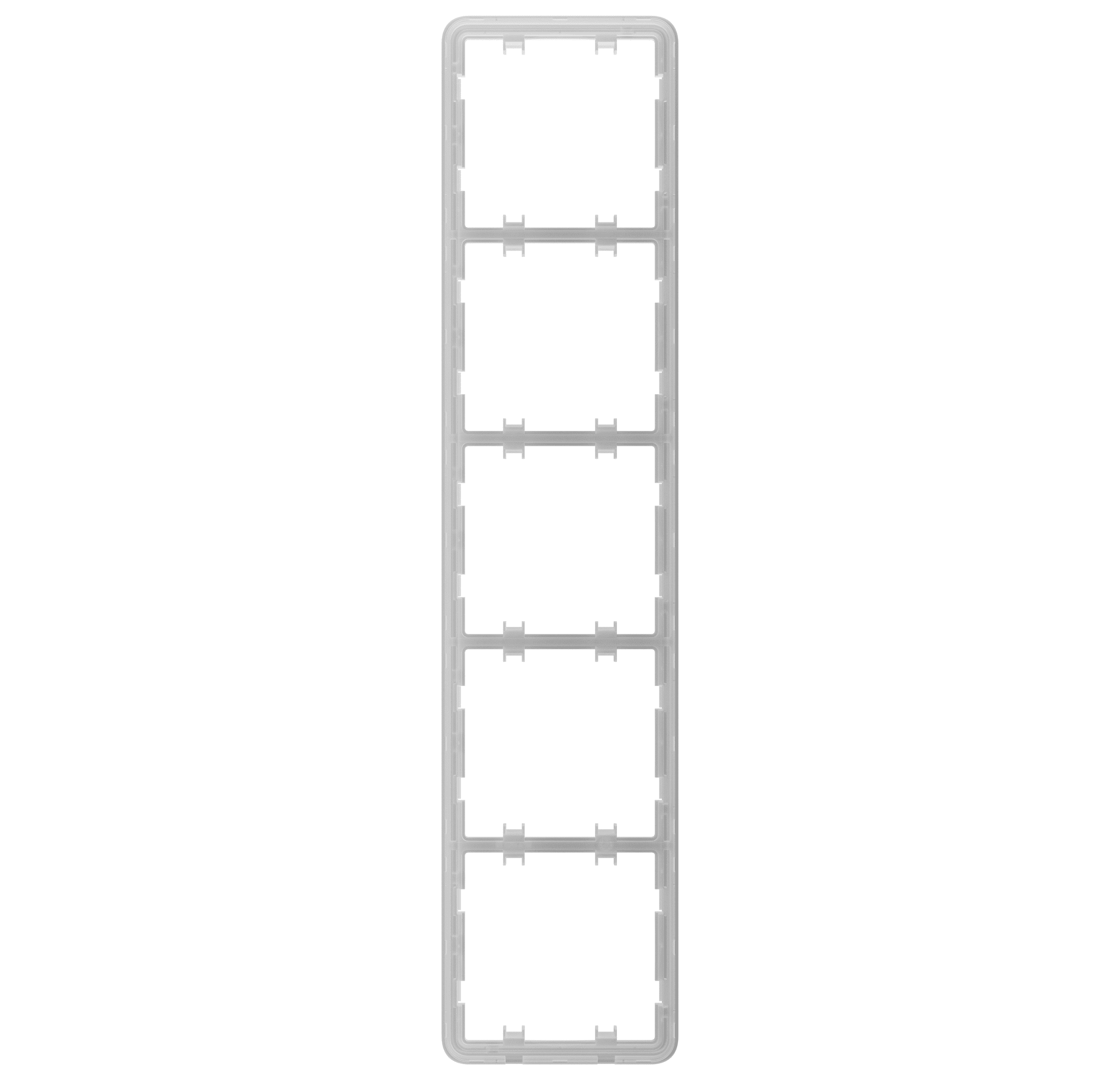
- Vertical frame for five devices.
Operating principle
LightSwitch Jeweller is a smart touch light switch. It controls the lighting in three ways: manually, through smartphone and PC apps, and using automation scenarios.
The device is installed without changing the electrical wiring of the object. The device does not require a neutral wire and works only from the power phase.
LightSwitch can be used without adding to a hub. In this mode, it works like a regular touch switch.
LightSwitch can control 5 to 600 W lighting devices. The kit includes a capacitor connected in parallel with the lighting device for low-power lamps. See the installation section of this manual for details.
LightSwitch frame has a LED backlight. The backlight is not bright, so it will not disturb users even if the device is installed near a bed. If necessary, a PRO or user with admin rights can disable the backlight in Ajax apps.
The product line of devices includes 1-gang, 2-gang, and 2-way light switches:
- 1-gang — control one lighting line (one lamp).
- 2-gang — control two lighting lines (two lamps).
- 2-way — control one light source from several seats.
The combined devices in a frame can be installed horizontally and vertically. The vertical installation is supported only by relays, touch-sensitive panels, and frames with the label vertical in the name.
Use the online Ajax switches and outlets configurator to assemble your custom set. Combine devices into a frame, pick the color, and download your configuration as PDF.
If necessary, LightSwitch can also control other devices. For example, one of the buttons can control the light, and the other one — room ventilation.
Manual control

LightSwitch allows to control the lighting when a hand is 15 millimetres away from the switch or when touching the touch-sensitive panel of the switch. Contactless control does not limit the possibility of use, even if hands are dirty or wet. The sensor reacts under any conditions. Therefore, the switch can be installed in crowded places: restaurants, factories, and offices.
The sensitivity of the touch-sensitive panel can be adjusted in the device settings in the app. Higher sensitivity ensures contactless operation, while lower values might require slightly touching the switch button.
LightSwitch sensor instantly reads the signal and transforms it into an electric pulse. LightCore receives this pulse and activates a relay that switches on/off the lighting device or another connected load, such as a cooker hood.
The entire LightSwitch panel is touch-sensitive. Therefore, the lighting can be controlled by touching or reaching any part of the touch-sensitive panel with a hand.
Remote control
Control via the app
LightSwitch can be used to control lighting manually and remotely through Ajax apps.
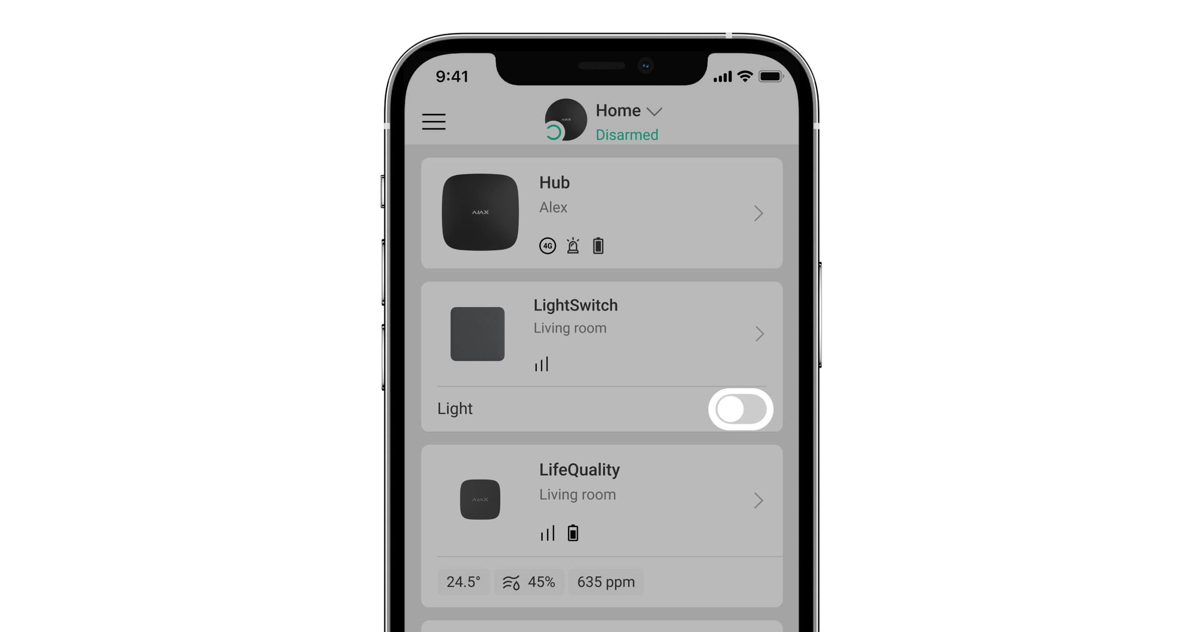
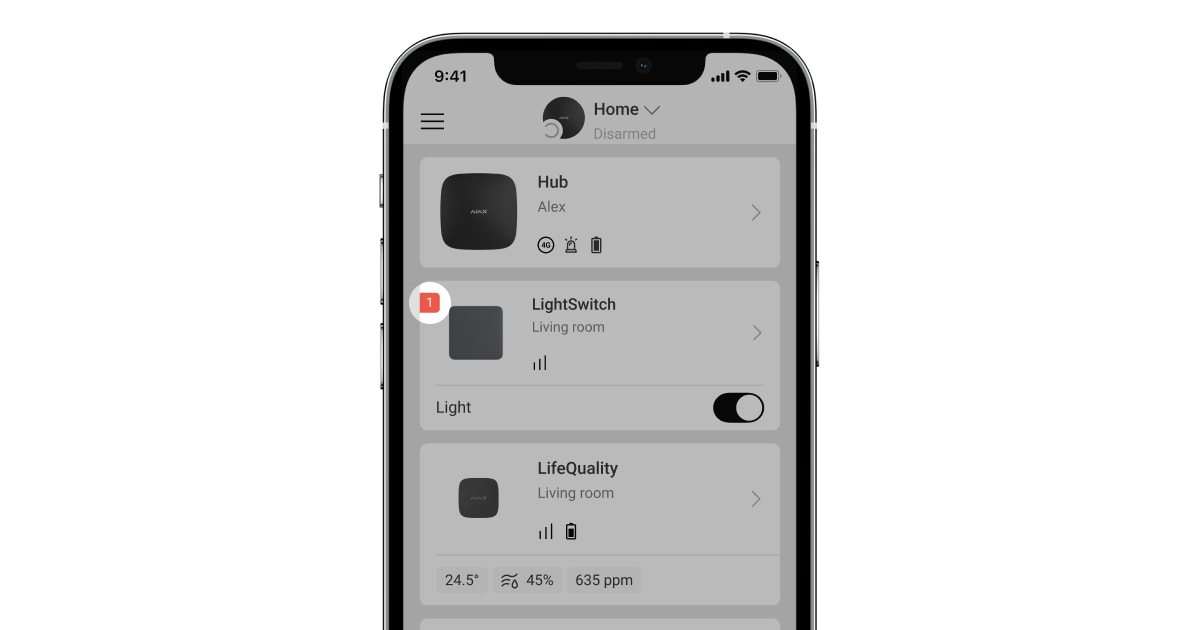
Сlick on the switch in the LightSwitch field in the Devices ![]() menu in the Ajax app, and the state of the switch contacts will change to the opposite. The lighting will be switched off or on. This way, system users can remotely control the lighting. For example, switch on the light in the room in advance before entering the room.
menu in the Ajax app, and the state of the switch contacts will change to the opposite. The lighting will be switched off or on. This way, system users can remotely control the lighting. For example, switch on the light in the room in advance before entering the room.
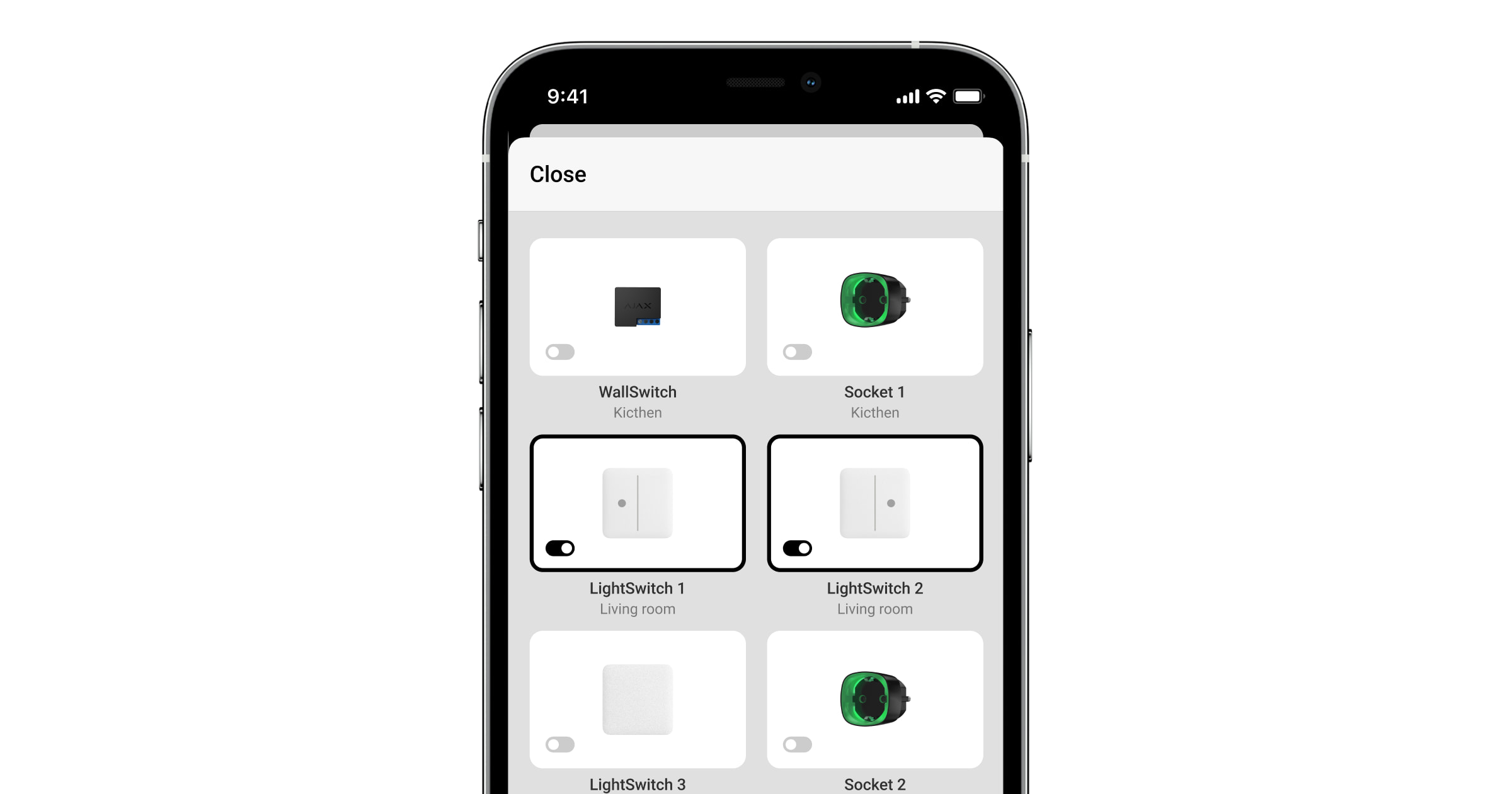
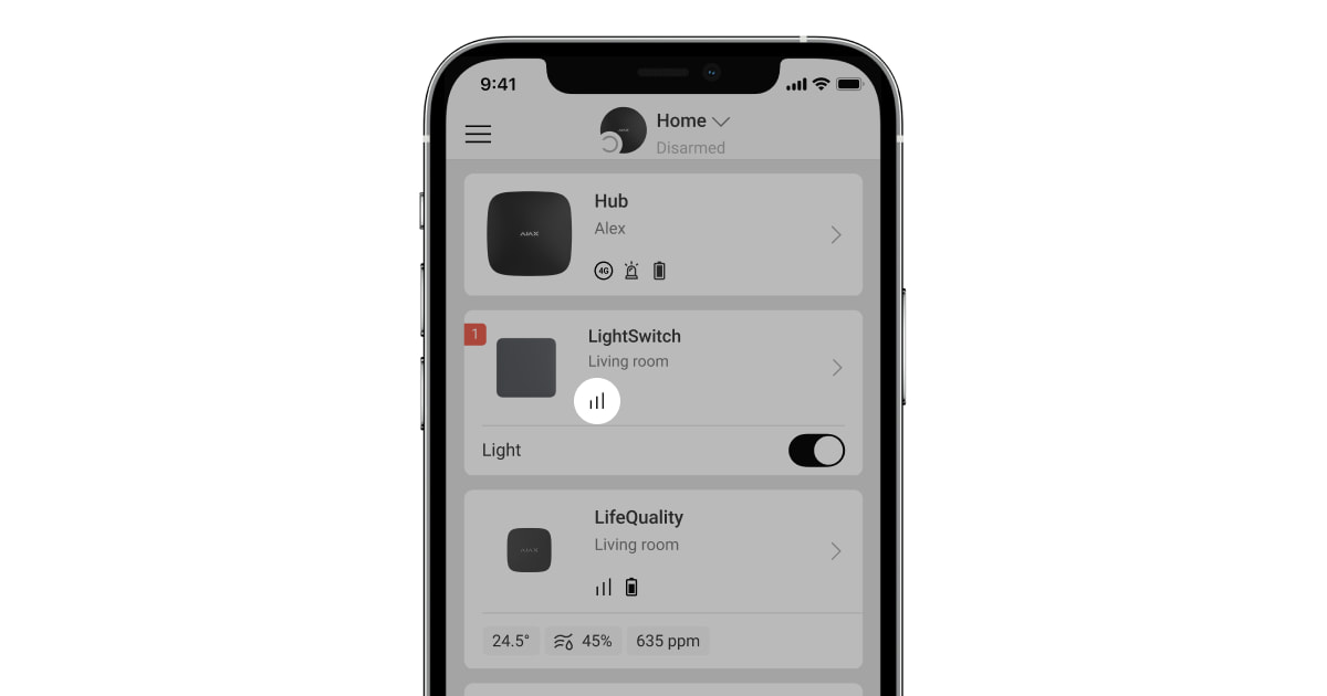
The lighting also can be controlled in the Control ![]() menu. To do this, go to the Control
menu. To do this, go to the Control ![]() menu and swipe up. All control devices added to the hub will appear in the list. Click on the switch in the LightSwitch field, and the state of the device’s contacts will change to the opposite. The lighting will be switched on or off.
menu and swipe up. All control devices added to the hub will appear in the list. Click on the switch in the LightSwitch field, and the state of the device’s contacts will change to the opposite. The lighting will be switched on or off.
Automation scenarios
Scenarios help automate security and reduce the number of routine actions. For example, set the lights to switch on by the schedule or when disarming the security system.
LightSwitch supports the following types of scenarios:
- By alarm
- By arming/disarming
- By schedule
- By Button pressing
- By temperature
- By humidity
- By CO2 concentration
- By LightSwitch pressing
Scenarios by humidity and CO2 concentration are available when LifeQuality is added to the system.
The system does not allow creating sequences of scenarios when executing one scenario activates the following one. This behaviour is intended to prevent accidental endless looping of such scenarios.
If the device is offline, it will not execute the scenario as it misses the scenario trigger (e.g., during a power outage or when the connection between the hub and device is lost).
Example: The automated action is scheduled for 10 a.m., so it must start at 10 a.m. The electrical power goes out at 9:55 a.m. and is restored ten minutes later. The automation scenario won’t start at 10 a.m. and will not start immediately after the power is back on. This scheduled action is missed.
Operation modes
LightSwitch can operate in one of two modes: bistable or pulse. The operating mode is set by a PRO or user with admin rights in Ajax apps in the device settings.
By default, LightSwitch operates in bistable mode. When controlling the lighting, it switches on or off.
When operating in pulse mode, the lighting can be switched on for the required time: from 10 seconds to 2 hours. This mode is useful, for example, if a user needs to switch on the lighting in the corridor for 5 minutes when disarming the security system.
Types of electrical protection of the switch
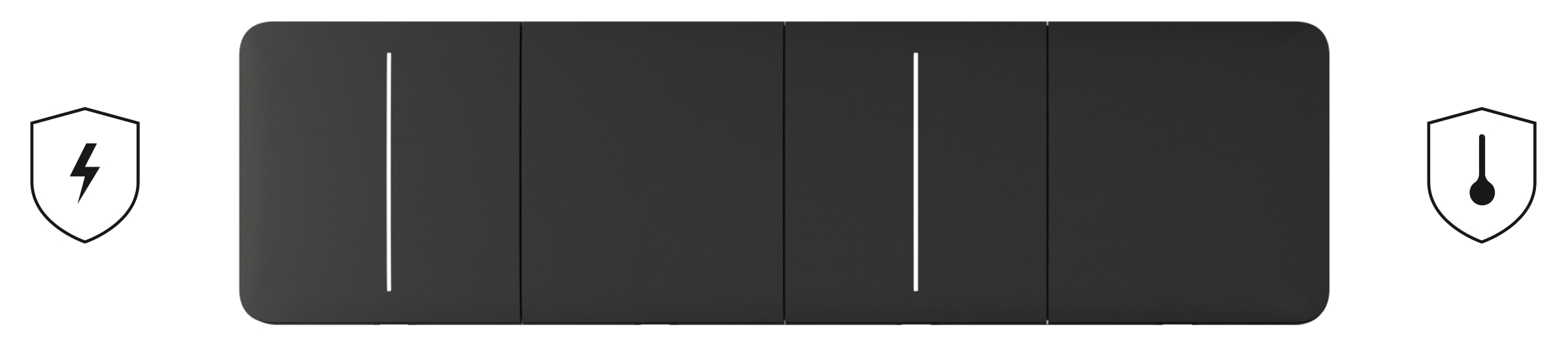
LightSwitch has two independent types of protection: current and temperature.
Current protection is activated if the load current on the switch is 2.6 A or more. If the protection triggers, LightSwitch switches off the power and sends a notification to Ajax apps. At the same time, the switch itself begins to flash red every second.
The power supply is not automatically restored when this protection is triggered. It can be reset by clicking on the toggle in the Ajax app or touching the touch-sensitive panel of the switch.
Temperature protection triggers if the temperature of the switch is greater than +60 °C. If this protection triggers, LightSwitch turns off the power and sends a notification to Ajax apps. The power supply resumes automatically when the switch temperature returns to normal.
Types of supported lamps
LightSwitch is compatible with the majority types of lamps and lighting devices. Detailed information on LightSwitch operation with different types of lamps is described in the table.
| Type of lamp | Compatibility | Supported power | Maximum current | Comments |
LED lamp / LED Corn lamp / LED panel / LED strip, etc.
    |
Yes | up to 600 W (up to 300 W per segment for 2-gang switch) |
2.6 А | |
Incandescent
 |
Yes | up to 600 W (up to 300 W per segment for 2-gang switch) |
2.6 А | |
Halogen
 |
Yes | up to 600 W (up to 300 W per segment for 2-gang switch) |
2.6 А | |
Fluorescent (conventional)
  |
Yes | up to 600 W (up to 300 W per segment for 2-gang switch) |
2.6 А | |
Fluorescent (compact)
  |
Not recommended | up to 480 W (up to 240 W per segment for 2-gang switch) |
2.6 А | Rare flashing is possible. |
| Smart lamps of any type | No | – | – |
Lamps with built-in brightness and color controllers, relays, radio modules, and microcontrollers. Stable operation can not be guaranteed. |
| Mixed light | No | – | – | Designed for non-home / non-office use. |
| Mercury-vapor | No | – | – | Designed for non-home / non-office use. |
| Metal-halide | No | – | – | Designed for non-home / non-office use. |
| Sodium-vapor | No | – | – | Designed for non-home / non-office use. |
Detection of lighting devices with insufficient power
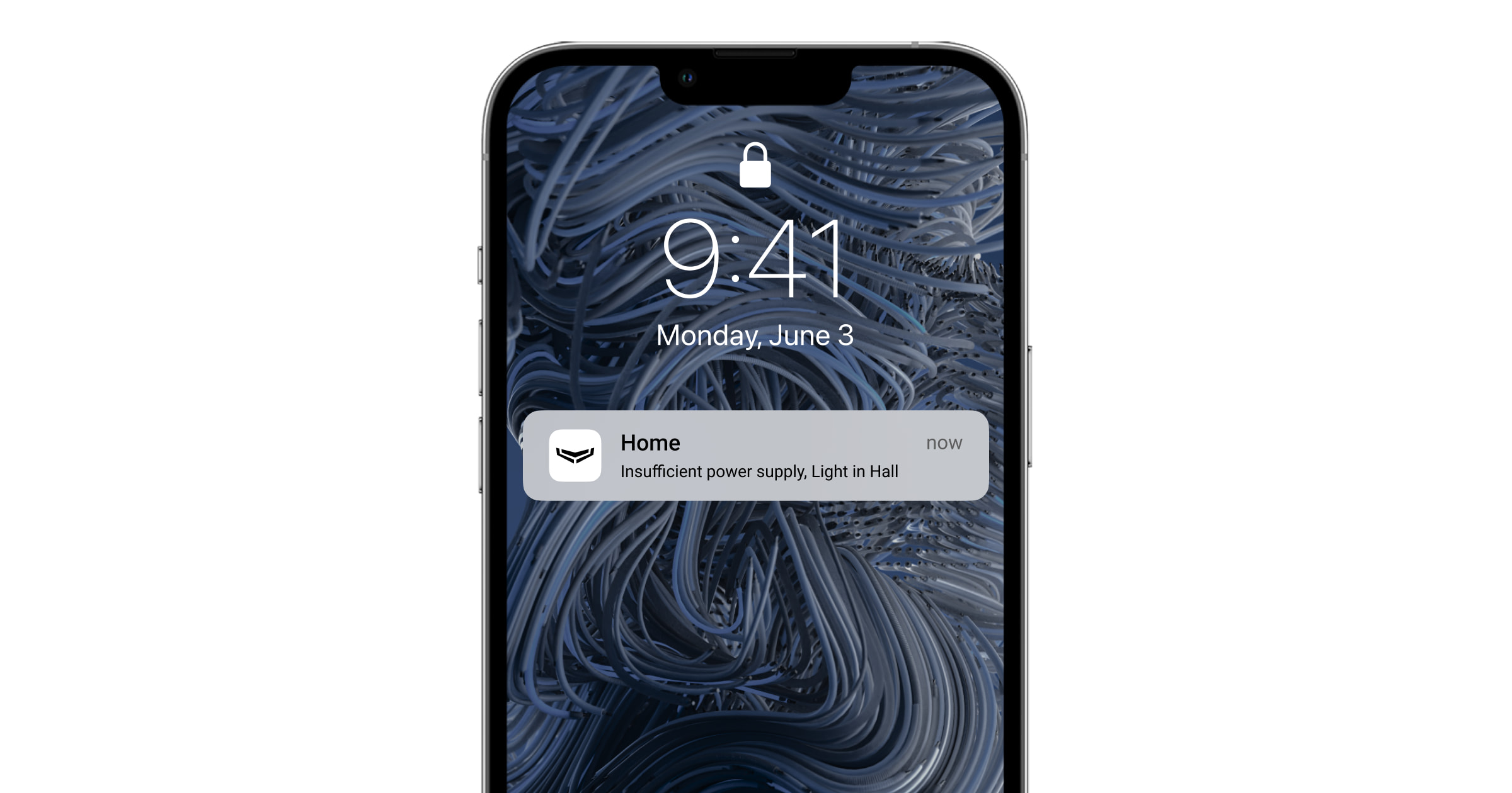
LightSwitch continuously checks its power supply parameters. If LightSwitch controls the power of a lighting device with insufficient power (up to 5 W), the system will notify the users of the Ajax system. In this case, it is necessary to replace the lighting device with a similar one with higher capacity or to connect a bundled capacitor in parallel with the lighting device.
Jeweller data transfer protocol

Jeweller is a radio protocol for fast and reliable two-way communication between a hub and connected devices. The protocol provides a range of wireless radio communication between LightSwitch and the hub (or range extender) up to 1,100 meters. This communication range allows installing switches not only in flats or private houses but also in open spaces or large warehouses.
Jeweller is responsible for transmitting all the necessary information and providing instant control of any number of LightSwitch devices in the system. Thanks to Jeweller, users can always control the light and see the current state of switches in Ajax apps anytime.
Jeweller supports block encryption with a floating key and authentication of devices at each communication session to prevent sabotage or device spoofing. The protocol involves regular polling of system devices by the hub at intervals of 12 to 300 seconds (depending on the Jeweller or Jeweller/Fibra settings) to monitor communication with all devices and show their statuses in the Ajax apps.
Sending events to the monitoring station
The Ajax system can transmit events and alarms to the PRO Desktop monitoring app as well as the Central Monitoring Station (CMS) via SurGard (Contact ID), SIA DC-09 (ADM-CID), ADEMCO 685, and other protocols.
Only events of lost connection between the switch and the hub (or range extender) are transmitted to the CMS. No other events are sent to third-party monitoring stations of security or monitoring companies. Use PRO Desktop to receive all switch events on the CMS.
Temperature or current protection triggering events are not sent to PRO Desktop as alarms.
The addressability of Ajax devices allows sending to PRO Desktop or to the CMS not only events but also the type of the device, its assigned name, security group, and room. The list of transmitted parameters may vary depending on the selected communication protocol with the CMS. The largest amount of information is transmitted to the PRO Desktop CMS.
The switch ID and loop (zone) number can be found in their states in the Ajax app.
Selecting the installation site
LightSwitch is designed to fit into standard sub-sockets of the European form factor (55). The device should be connected to the power phase wire for proper operation. Connecting the neutral wire is not required.
Do not connect the neutral wire to the LightSwitch terminals. This can damage the device.
When installing LightSwitch, consider the Jeweller signal strength. It is determined by the ratio of the number of undelivered or corrupted data packages to those expected that are exchanged between the switch and the hub or range extender over a certain period.
The signal strength is indicated by the icon ![]() in the Devices
in the Devices ![]() menu. The signal strength is also indicated in the switch states.
menu. The signal strength is also indicated in the switch states.
Signal strength value:
- Three bars — excellent signal strength.
- Two bars — good signal strength.
- One bar — low signal strength. Stable operation is not guaranteed.
- Crossed out icon — no signal. Stable operation is not guaranteed.
Check the Jeweller signal strength at the installation site. The switch should have a signal strength of two or three bars. To roughly calculate the signal strength at the place of installation, use a radio communication range calculator.
With a signal strength of one or zero bars, the stable operation of the switch is not guaranteed. Use the radio signal range extender if the selected installation site has a signal strength of fewer than two bars.
Do not install the switch
- Outdoors. The device has an IP20 protection class. This may result in device failure or incorrect operation.
- On metal structures. This can lead to incorrect operation of the sensor: it may not respond to touch or give false triggerings.
- In rooms with humidity and temperature that are outside the permissible limits. Doing so may cause the device to malfunction or not work properly. The operating temperature range is from –10 to +40 °C. The permissible humidity is up to 75% without condensation.
- In places with low or unstable signal strength. This may result in a loss of communication between the hub (or range extender) and the switch.
Installation
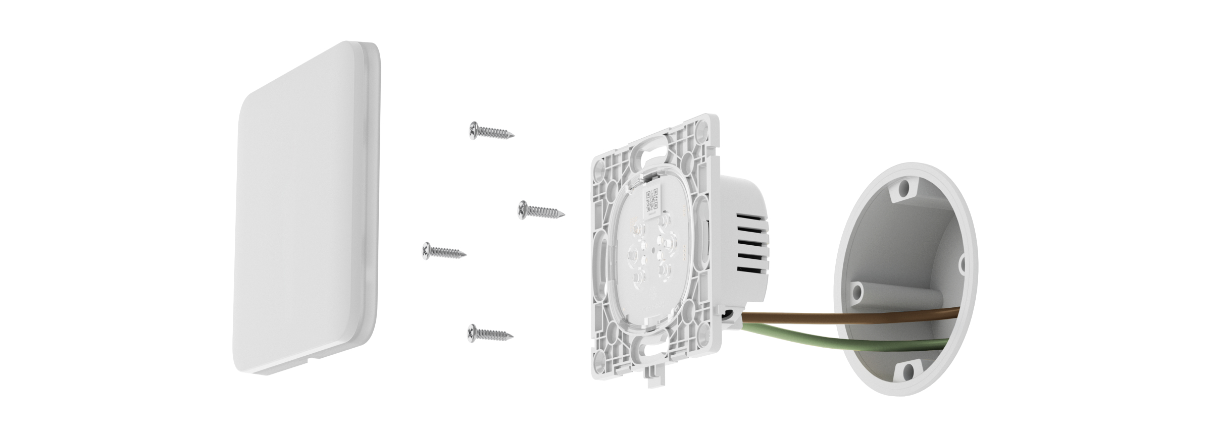
Only a qualified electrician or installer should install LightSwitch. Do not switch on the power at the switches before installing the touch-sensitive panels. Also, do not try to register the device before installing the touch-sensitive panel, as it contains antennas necessary for communication with the hub.
Before installing the switch, ensure that the optimal location has been selected and that it complies with the requirements of this manual. When installing and operating the device, follow the general electrical safety rules for using electrical appliances and the requirements of electrical safety regulations.
For connection, use cables with a cross-section recommended by the manufacturer of the lighting device. LightSwitch cannot be connected to electric circuits with a load exceeding 600 W. The device does not require a neutral wire and works only from the power phase.
After installing and connecting the switch, be sure to run the Jeweller Signal Strength Test and check the operation of the device: how it responds to touch, and whether it switches on/off the lights.
The installed touch-sensitive panel can be removed from LightSwitch with a flat screwdriver. To complete this, insert it into the hole from below and turn the screwdriver.
Ensure that the sticker shown in the image below has been removed from the touch-sensitive panel before installing it on LightCore. This is necessary for correct LED indication of the device.
Installation of 1-gang switch
- De-energize the power cable to which the LightCore relay will be connected.
- Prepare the mounting boxes and remove the pre-installed breakers, if any.
- Connect the wires to the LightCore relay according to the diagram below:
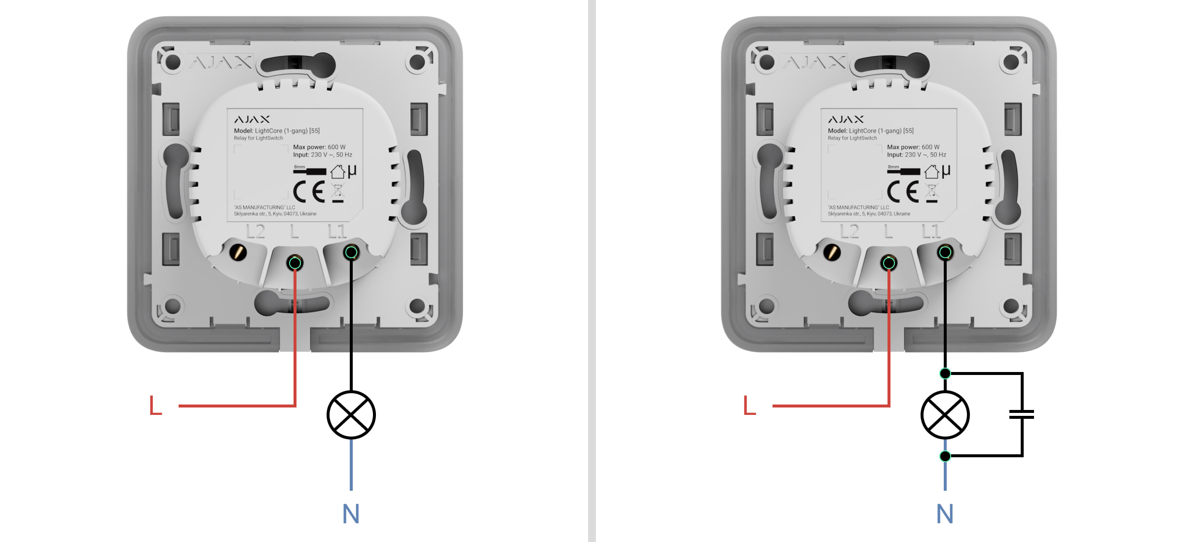
- Connect the power phase wire to the LightCore relay (terminal L).
- Connect the power wire of the lighting device to the LightCore relay (terminal L1).
- Connect the bundled capacitor in parallel with the lighting appliance if:
- its power is less than 5 W (an approximate value that can vary depending on the type and technical characteristics of the lighting appliance);
- it flashes in a turned-off state;
- LightSwitch is malfunctioning or unstable;
- adding LightSwitch to the system fails (with an installed touch-sensitive panel);
- another abnormal operation of LightSwitch or lighting appliance is observed.

Do not connect the neutral wire to the LightSwitch terminals. LightSwitch operates only from the power phase.
- Install the LightCore relay in the mounting box.
- Secure the LightCore relay with the bundled fasteners.
- Install the remaining LightCore relays if necessary.
- Install the frame for the appropriate number of seats if mounting multiple switches.
- Install the necessary touch-sensitive panels.
- Switch on the power.
- Add switches using the Ajax app.
Installation of 2-gang switch
- De-energize the power cable to which the LightCore relay will be connected.
- Prepare the mounting boxes and remove the pre-installed breakers, if any.
- Connect the wires to the LightCore relay according to the diagram below:
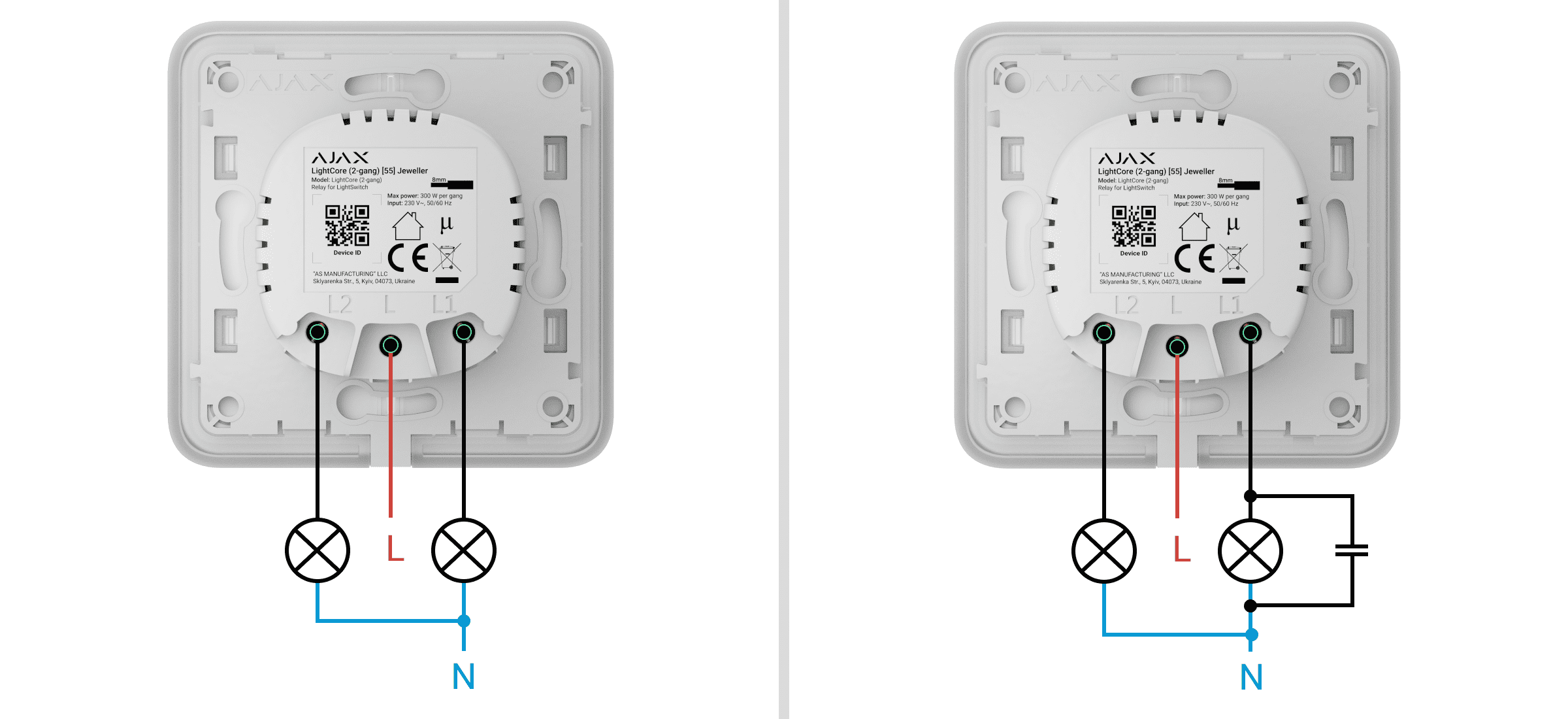
- Connect the power phase wire to the LightCore relay (terminal L).
- Connect the power wire of the first lighting device to the LightCore relay (terminal L1).
- Connect the power wire of the second lighting device to the LightCore relay (terminal L2).
- Connect the bundled capacitor in parallel with one of the lighting appliances if:
- their power is less than 5 W (an approximate value that can vary depending on the type and technical characteristics of the lighting appliance);
- they flash in a turned-off state;
- LightSwitch is malfunctioning or unstable;
- adding LightSwitch to the system fails (with an installed touch-sensitive panel);
- another abnormal operation of LightSwitch or lighting appliance is observed.
Do not connect the neutral wire to the LightSwitch terminals. LightSwitch operates only from the power phase.
- Install the LightCore relay in the mounting box.
- Secure the LightCore relay with the bundled fasteners.
- Install the remaining LightCore relays if necessary.
- Install the frame for the appropriate number of seats if mounting multiple switches.
- Install the necessary touch-sensitive panels.
- Switch on the power.
- Add switches using the Ajax app.
Installation of 2-way switch
- De-energize the power cable to which the LightCore relay and the third-party switch will be connected.
- Prepare the mounting boxes and remove the pre-installed breakers, if any.
- Connect the wires to the LightCore relay and the third-party switch according to the diagram below:
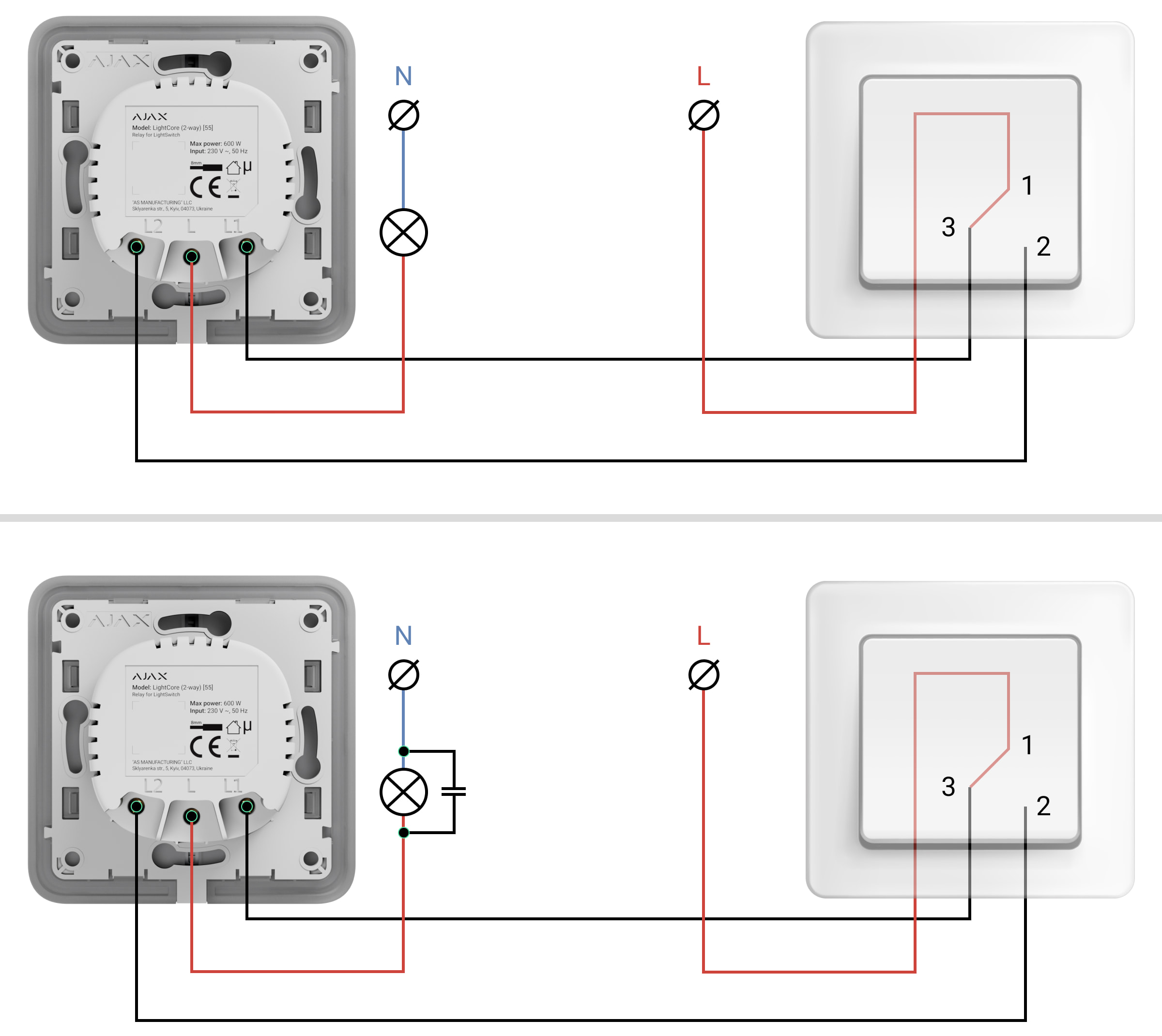
- Connect the power phase wire to the LightCore relay (terminal L).
- Connect the LightCore relay (terminal L1) to the first terminal of the third-party switch according to the manufacturer’s diagram.
- Connect the LightCore relay (terminal L2) to the second terminal of the third-party switch according to the manufacturer’s diagram.
- Connect the bundled capacitor in parallel with the lighting appliance if:
- its power is less than 5 W (an approximate value that can vary depending on the type and technical characteristics of the lighting appliance);
- it flashes in a turned-off state;
- LightSwitch is malfunctioning or unstable;
- adding LightSwitch to the system fails (with an installed touch-sensitive panel);
- another abnormal operation of LightSwitch or lighting appliance is observed.
Do not connect the neutral wire to the LightSwitch terminals. LightSwitch operates only from the power phase.
- Install the LightCore relay in the mounting box.
- Secure the LightCore relay with the bundled fasteners.
- Install the remaining LightCore relays if necessary.
- Install the frame for the appropriate number of seats if mounting multiple switches.
- Install the necessary touch-sensitive panels.
- Switch on the power.
- Add switches using the Ajax app.
- De-energize the power cable to which the LightCore relay will be connected.
- Prepare the mounting boxes and remove the pre-installed breakers, if any.
- Connect the wires to the LightCore relay according to the diagram below:
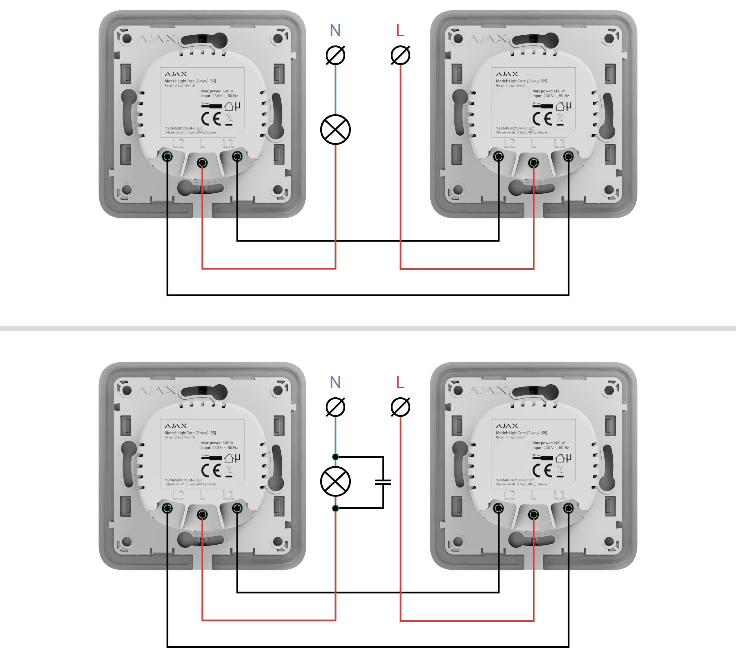
- Connect the power phase wire to the first LightCore relay (terminal L).
- Connect the power phase wire to the second LightCore relay (terminal L).
- Connect the first LightCore relay (terminal L1) to the second LightCore relay (terminal L2).
- Connect the first LightCore relay (terminal L2) to the second LightCore relay (terminal L1).
- Connect the bundled capacitor in parallel with the lighting appliance if:
- its power is less than 5 W (an approximate value that can vary depending on the type and technical characteristics of the lighting appliance);
- it flashes in a turned-off state;
- LightSwitch is malfunctioning or unstable;
- adding LightSwitch to the system fails (with an installed touch-sensitive panel);
- another abnormal operation of LightSwitch or lighting appliance is observed.
Do not connect the neutral wire to the LightSwitch terminals. LightSwitch operates only from the power phase.
- Install the LightCore relays in turns into the mounting boxes.
- Secure the LightCore relay with the bundled fasteners.
- Install the remaining LightCore relays if necessary.
- Install a frame for the appropriate number of seats.
- Install the necessary touch-sensitive panels.
- Switch on the power.
- Add switches using the Ajax app.
- De-energize the power cable to which the LightCore relay and the third-party intermediate switch will be connected.
- Prepare the mounting boxes and remove the pre-installed breakers, if any.
- Connect the wires to the LightCore relay and the third-party switch according to the diagram below:
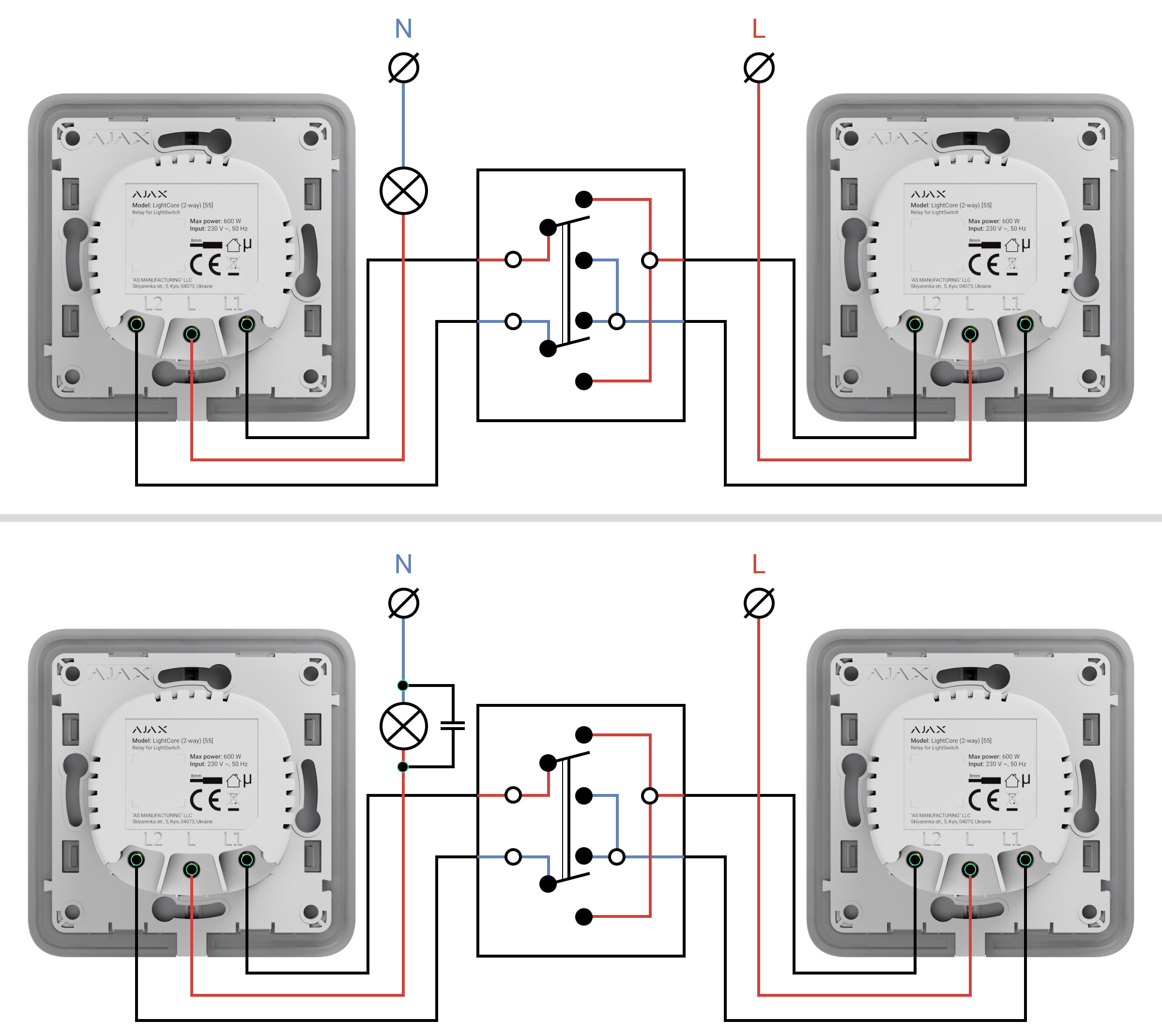
- Connect the power phase wire to the first LightCore relay (terminal L).
- Connect the power phase wire to the second LightCore relay (terminal L).
- Connect the first LightCore relay (terminal L1) to the intermediate switch according to the manufacturer’s diagram.
- Connect the first LightCore relay (terminal L2) to the intermediate switch according to the manufacturer’s diagram.
- Connect the second LightCore relay (terminal L1) to the intermediate switch according to the manufacturer’s diagram.
- Connect the second LightCore relay (terminal L2) to the intermediate switch according to the manufacturer’s diagram.
- Connect the bundled capacitor in parallel with the lighting appliance if:
- its power is less than 5 W (an approximate value that can vary depending on the type and technical characteristics of the lighting appliance);
- it flashes in a turned-off state;
- LightSwitch is malfunctioning or unstable;
- adding LightSwitch to the system fails (with an installed touch-sensitive panel);
- another abnormal operation of LightSwitch or lighting appliance is observed.
Do not connect the neutral wire to the LightSwitch terminals. LightSwitch operates only from the power phase.
- Install the LightCore relays in turns into the mounting boxes.
- Secure the LightCore relay with the bundled fasteners.
- Install the remaining LightCore relays if necessary.
- Install a frame for the appropriate number of seats.
- Install the necessary touch-sensitive panels.
- Switch on the power.
- Add switches using the Ajax app.
Adding to the system
Before adding a device
- Install the Ajax app.
- Log in to your account or create a new one.
- Select a space or create a new one.

The space functionality is available for apps of such versions or later:
- Ajax Security System 3.0 for iOS;
- Ajax Security System 3.0 for Android;
- Ajax PRO: Tool for Engineers 2.0 for iOS;
- Ajax PRO: Tool for Engineers 2.0 for Android;
- Ajax PRO Desktop 4.0 for macOS;
- Ajax PRO Desktop 4.0 for Windows.
- Add at least one virtual room.
- Add a compatible hub to the space. Ensure the hub is switched on and has internet access via Ethernet, Wi-Fi, and/or mobile network.
- Ensure the space is disarmed, and the hub is not starting an update by checking statuses in the Ajax app.
Only a PRO or a space admin with the rights to configure the system can add a device to the hub.
Pairing with the hub
Do not switch on the power at the switches before installing the touch-sensitive panels. Also, do not try to register the device before installing the touch-sensitive panel, as it contains antennas necessary for communication with the hub.
LightSwitch should be within the coverage area of the hub’s radio network to pair with the hub. To work via the radio signal range extender, pair LightSwitch with the hub and then add it to the range extender. This can be done in the range extender settings. Detailed instructions can be found in the manual for the relevant range extender.
The hub and the switch operating at different frequencies are incompatible. The radio frequency range of the device may vary by region. We recommend buying and using Ajax devices in the same region. Please contact Technical Support for information on the operating frequency range.
LightSwitch only works with one hub. When paired with a new hub, the switch stops sending commands to the old one. When added to a new hub, the switch is not removed from the device list of the old hub. This must be done through the Ajax app.
To add LightSwitch to the hub:
- Install LightSwitch if you haven’t done so before.
- Open the Ajax app.
- Select the hub if you have several of them or use the Ajax PRO app.
- Go to the Devices
 tab and click Add device.
 - Enter the name of the device.
- Scan the QR code of the device or enter the ID manually. QR code is located on the rear panel of LightCore, the front panel of LightCore, and the device packaging. The device ID can be found below the QR code.
- Select the virtual room and security group (if the group mode is enabled).
- Click Add — the countdown will begin.
If the maximum number of devices is added to the hub, you will get a notification about exceeding the device limit when you try to add the switch in the Ajax app. The number of devices that can be added to the hub depends on the central unit model and the Jeweller (or Jeweller/Fibra) settings.
- In a few seconds, LightSwitch will appear in the list of hub devices. Updating the device statuses in the list depends on the Jeweller (or Jeweller/Fibra) settings. The default value is 36 seconds.
If the connection fails, try again in 5 seconds. But this time, during the countdown, press and hold the switch button for at least 3 seconds. If adding a 2-gang switch, press either button.
If you press and hold the button of LightSwitch not paired with the hub for at least 3 seconds, the switch flashes green every second for one minute to inform you that it is not paired with the hub.
Functionality testing
After installation, test the operation of the switch: how it responds to touch and whether it switches on/off the light.
The Ajax system provides several tests to select the location of devices correctly. Tests do not start immediately. However, the waiting time does not exceed the duration of one “hub — device” ping interval. The default value is 36 seconds. The device ping interval can be changed in the Jeweller (or Jeweller/Fibra) menu in the hub settings.
The Jeweller Signal Strength Test is available for LightSwitch. The test allows for determining the strength and stability of the signal at the installation site.
To run a test in the Ajax app:
- Select the hub if you have several of them or use the PRO app.
- Go to the Devices tab.
- Select LightSwitch.
- Go to Settings
 .
. - Select Jeweller Signal Strength Test.
- Run and perform the test using the prompts in the app.
Icons
Icons display some of LightSwitch states. Icons can be checked in the Ajax app in the Devices ![]() tab.
tab.
| Icon | Meaning |
|
Jeweller Signal Strength displays the signal strength between the hub and the switch. |
|
| The switch communicates with the hub via a radio signal range extender. | |
|
Current protection was activated. |
|
|
Temperature protection was activated. |
|
| The device has lost connection with the hub or the hub has lost connection with the Ajax Cloud server. | |
|
The device has not been transferred to the new hub. |
States
The states include information about the switch and its operating parameters. LightSwitch states can be seen in the Ajax app. To see them:
- Open the Ajax app.
- Select the hub if you have several of them or use the PRO app.
- Go to the Devices tab.
- Select LightSwitch in the list.
| Parameter | Meaning |
| Data import | Displays the error when transferring data to the new hub:
|
| Malfunction |
Clicking on The field is displayed only if a malfunction is detected. |
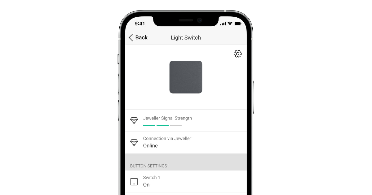
| Jeweller signal strength |
Signal strength between the switch and the hub (or the range extender) via the Jeweller channel. Recommended values: 2–3 bars. Jeweller is a protocol for transmitting LightSwitch events and commands. |
| Connection via Jeweller | Connection status between the switch and the hub (or range extender):
|
| Range extender name | Status of switch connection to the radio signal range extender:
The field is displayed if the switch operates via a radio signal range extender. |
| Name of the button/buttons | The section that shows the state of the switch buttons:
|
| Operating time | The time during which the lighting will be switched on. The field is displayed when the device operates in pulse mode (the Shutoff by Timer option is activated). |
| Lock switch buttons | The switch button lock status is displayed as follows:
|
| Switch sensitivity | The level of switch sensitivity:
Higher sensitivity ensures contactless operation, while lower values might require slightly touching the switch button. |
| Backlight | The status of the switch frame backlight is displayed as follows:
|
| Recover state after power outage | The status of the recovering switch state after a power outage:
Available for LightSwitch (1-gang) Jeweller, LightSwitch (2-gang) Jeweller, and LightSwitch (2-way) Jeweller with firmware version 5.60.1.42 or later. |
| Permanent deactivation | Displays the status of the device’s permanent deactivation setting:
|
| One-time deactivation | Displays the status of the device’s one-time deactivation setting:
|
| Firmware | Device firmware version. |
| Device ID | LightSwitch ID. Also available on the QR code on the device enclosure and its package box. |
| Device No. | Number of the switch loop (zone). |
Settings
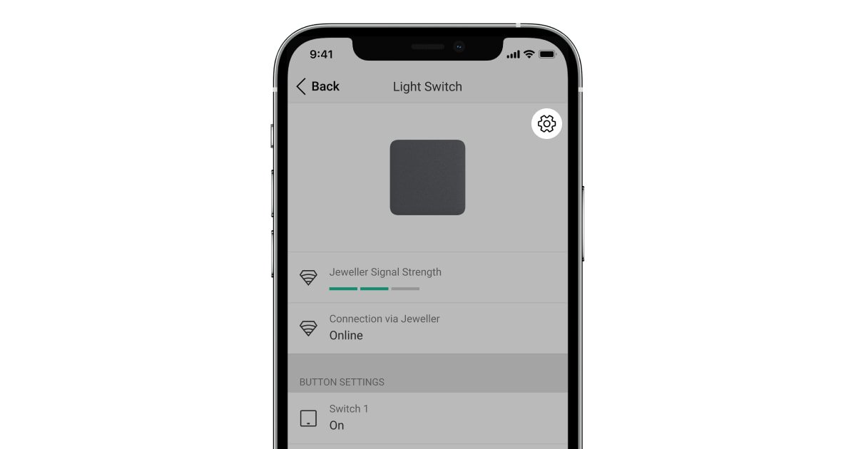
To change the switch settings in the Ajax app:
- Open the Ajax app.
- Select the hub if you have several of them or use the PRO app.
- Go to the Devices tab.
- Select LightSwitch in the list.
- Go to Settings by clicking on the gear icon .
- Set the required settings.
- Click Back to save the new settings.
| Settings | Meaning |
| Name |
LightSwitch name. Displayed in the text of SMS and events feed notifications. To change the switch name, click on the text field. The name can contain up to 12 Cyrillic characters or up to 24 Latin symbols. |
| Room |
Virtual room to which LightSwitch is assigned. To change the room, click on the field. The room name is displayed in the text of SMS and events feed notifications. |
| Color | Option to select a color for the switch icon in the app. In the app, one of 8 colors can be chosen:
The list of colors corresponds to the colors of the touch-sensitive panels. |
| Notifications | Switch notification settings in the app:
Note that turning on/off and scenario execution notifications are disabled by default. |
| Backlight | Option for the switch frame backlight setup. Activate this option to switch backlit when the lighting is off. |
| Lock switch buttons | Option for the switch button lock setup. Activate if you want the switch not to respond to touch. Users will be able to control the switch in the app only. |
| Recover state after power outage |
Allows configuring the recovering switch state after a power outage. When enabled, the switch returns to the same state (turned on or off) as before the power outage once the power is restored. Available for LightSwitch (1-gang) Jeweller, LightSwitch (2-gang) Jeweller, and LightSwitch (2-way) Jeweller with firmware version 5.60.1.42 or later. |
| Switch sensitivity | Adjust the level of switch sensitivity:
Higher sensitivity ensures contactless operation, while lower values might require slightly touching the switch button. |
| Button name | To change the name, click on the text field. |
| Shutoff by timer | Option for deactivating the switch after a set time. If this option is enabled, you need to set a time: from 10 seconds to 2 hours. |
| Scenarios |
Opens the menu for creating and configuring automation scenarios. Use scenarios to automate security, for routine activities, and to improve comfort. For example, to switch on the lighting according to the schedule or switch it off when the system is armed. |
| Jeweller signal strength test |
Starts testing the Jeweller signal strength between the switch and the hub (or range extender). The test allows checking the Jeweller signal strength and the stability of the connection between the switch and the hub (or range extender) to select the optimal installation site. |
| User guide | Opens the switch User Manual in the Ajax app. |
| Permanent deactivation |
Allows to deactivate the device without removing it from the system. Two options are available:
After deactivation, LightSwitch will retain its state at the time of deactivation: on or off. |
| One-time deactivation |
Allows the user to disable events of the device until the first disarm. Two options are available:
After deactivation, LightSwitch will retain its state at the time of deactivation: on or off. |
| Delete device | Disconnects the device from the hub and deletes its settings. |
LED indication

LightSwitch has a backlight that makes the switch visible in the dark. If the frame of the device is backlit, the light is off. When the light is on, the frame is not backlit. The backlight is not bright, so it will not disturb users even if the device is installed near a bed. The backlight can be turned off in the Ajax app if necessary.
If the temperature or current protection of LightSwitch has been triggered or the touch-sensitive panel removed, the switch flashes red every second.
To inform you that LightSwitch is not paired with the hub, it flashes green every second for one minute:
- when you connect LightSwitch to the power supply the first time;
- when you press and hold the LightSwitch button for at least 3 seconds.
Malfunctions
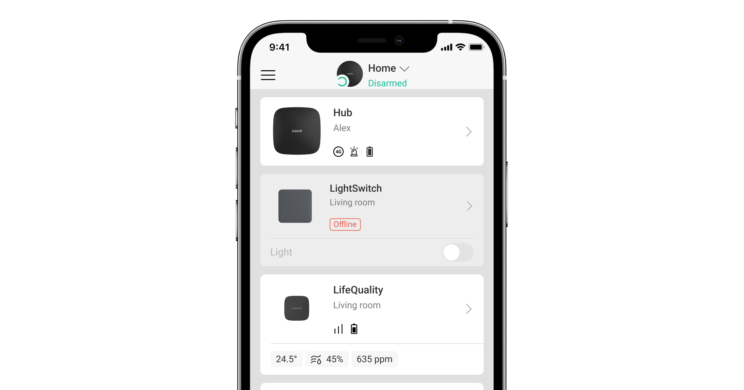
When a device identifies a fault (for example, there is no connection with the hub), the Ajax app displays a malfunction counter in the device field.
All malfunctions are shown in the switch states. Fields with malfunctions will be highlighted in red.
A malfunction is displayed if:
- Current protection was activated.
- Temperature protection was activated.
- A device with insufficient power is connected.
- An insufficient power supply is detected.
- There is no communication between LightSwitch and the hub (or range extender).
What to do in case of communication loss with the device
LightSwitch may lose communication with the hub for the following reasons:
- Power is no longer supplied.
- The touch-sensitive panel has been removed (it has antennas on it, which are necessary for communication with the hub or range extender).
- The lighting device is faulty (for example, the incandescent lamp burned out).
- A device with insufficient power (up to 5 W) is connected.
- LightSwitch malfunction.
If an event about the loss of communication with the switch is received, the installer should check:
- Power supply of LightSwitch.
- The presence of a touch-sensitive panel on the switch.
- The operability of the lighting device.
If LightSwitch controls a lighting device with insufficient power (up to 5 W), it is necessary to replace the lighting device with a similar one with a higher power or connect a bundled capacitor in parallel with the lighting device.
Maintenance
Check the functioning of the switch regularly. Clean the enclosure from dust, cobwebs, and other contaminants as they emerge. Use a soft dry cloth suitable for equipment care. Do not use substances that contain alcohol, acetone, petrol, and other active solvents to clean the device.
Technical specifications
Complete set
LightSwitch is a prefabricated smart light switch. All parts are purchased separately.
Use the online Ajax switches and outlets configurator to assemble your custom set. Combine devices into a frame, pick the color, and download your configuration as PDF.
Warranty
The warranty for the products of the Limited Liability Company “Ajax Systems Manufacturing” is valid for 2 years after purchase.
If the device does not operate properly, we recommend contacting support service first, as in most cases, technical issues can be resolved remotely.
Contact Technical Support:
