Ajax WaterStop Jeweller is a smart water shutoff valve. Operates as part of an automated water leak prevention system. Controls it in Ajax apps, through a button on the enclosure, a lever on a shutoff valve, as well as automation scenarios.
An Ajax hub is required for operation. A list of compatible hubs and range extenders is available here.
Ajax WaterStop communicates with the hub using an encrypted Jeweller radio protocol. The communication range without obstacles is up to 1,100 meters.
Runs on pre-installed batteries for up to three years. It can also be powered by a third-party power supply unit with 7.5–14 V⎓ and operating current of at least 1.8 A.
Functional elements
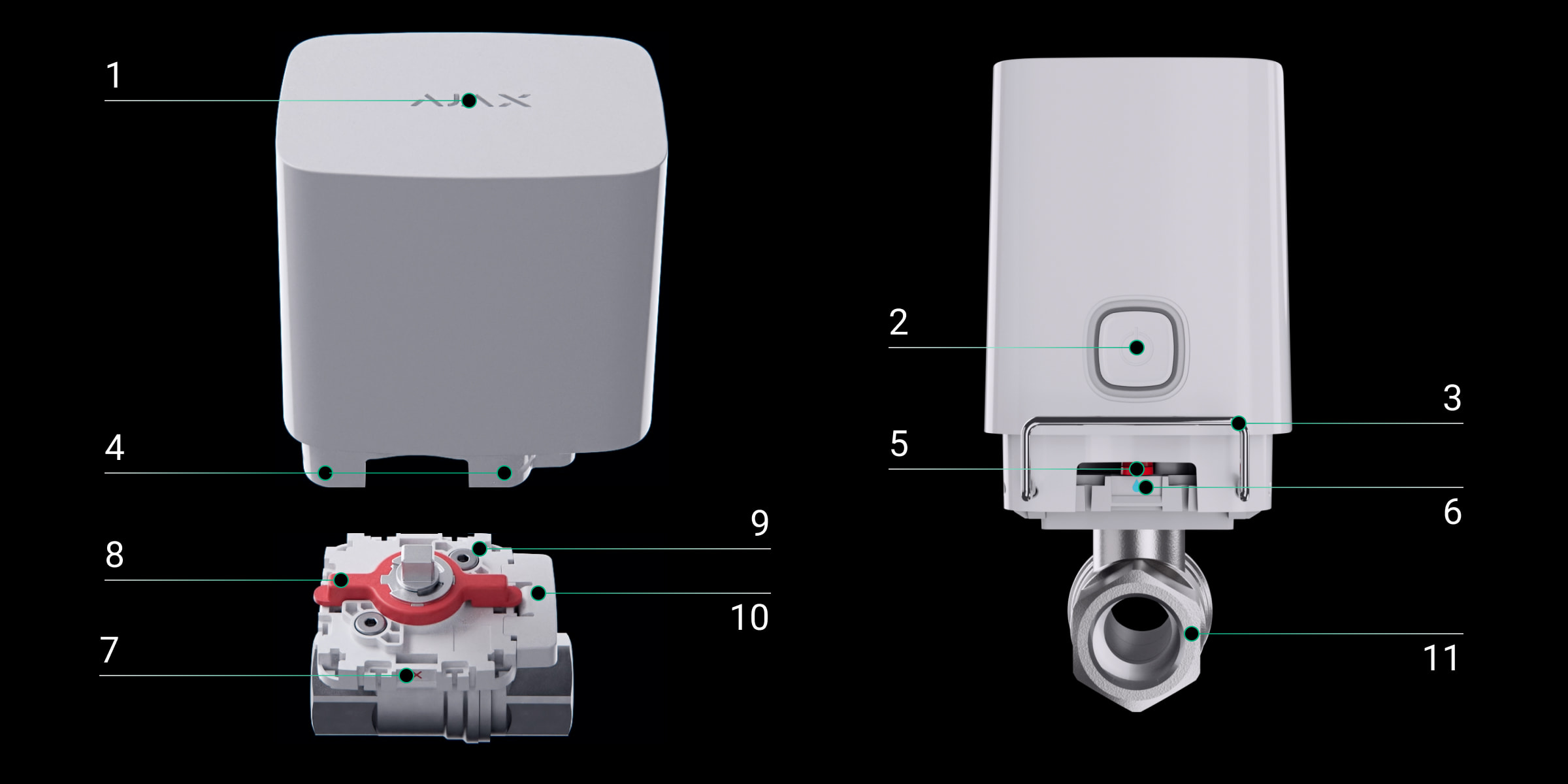
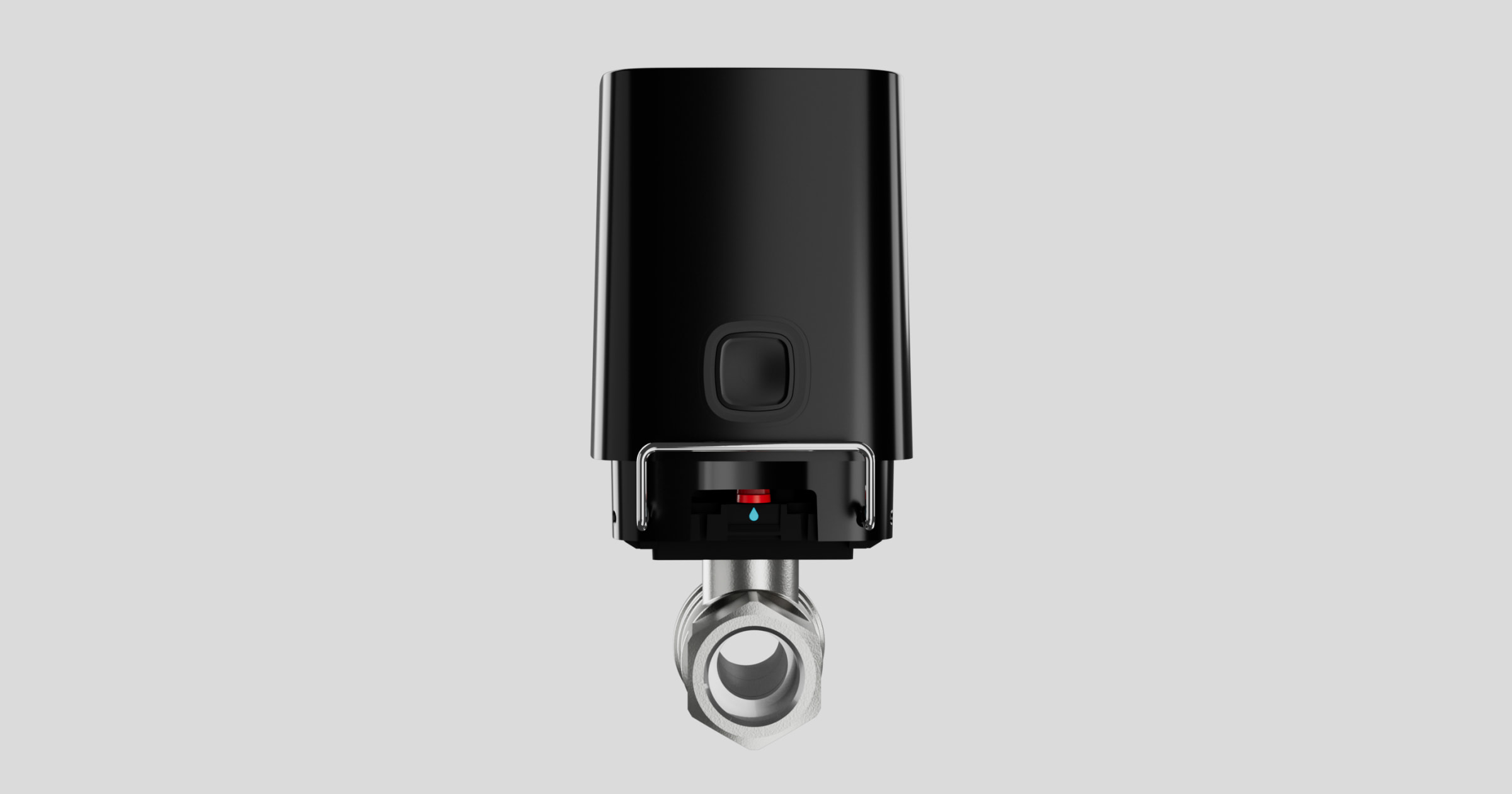
- LED indicator. Reports the status of Ajax WaterStop.
- Control button. Activates and deactivates the device when the button is pressed for three seconds. When short pressed (for a second), it controls the water supply.
- Mounting lockers. Supplied in two options: standard (pre-installed) and anti-sabotage.
- Holes for installation of a mounting locker. The locker can be installed on any of the four sides of Ajax WaterStop.
- Mechanical indicator of shutoff valve status: open or closed.
- Position mark Open. The water is open when the mechanical indicator corresponds to this position.
- Position mark Closed. The water is shut off when the mechanical indicator corresponds to this position.
- Lever on the mount. It is designed for manual control of a shutoff valve.
- Mounting platform. It is installed between the shutoff valve and the electric drive.
- Removable part of the mount. Allows changing the position of the electric valve by 180° without removing the mount.
- RuB valve. Ajax WaterStop is supplied with a BSPP threads valve in one of three sizes: ½” (DN 15, 15 mm), ¾” (DN 20, 20 mm), or 1″ (DN 25, 25 mm).

- Tamper button. Reacts to the removal of the electric actuator from the mount.
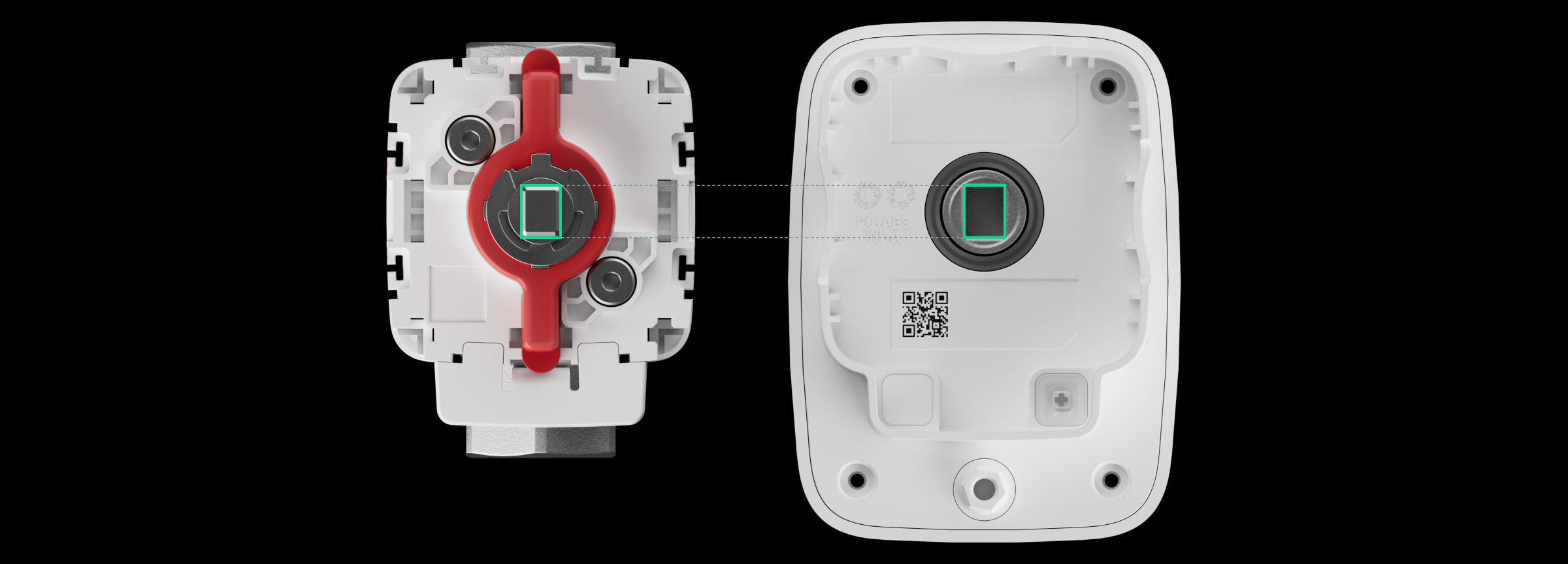
- QR code and ID/serial number of the device. It is used to connect Ajax WaterStop to the Ajax system.
- The rotary part of the water shutoff mechanism (electric actuator coupling).
- Plug for a third-party 7.5–14 V⎓ power supply connection.
Operating principle
Ajax WaterStop Jeweller is a smart water shutoff valve with remote control. Operates as part of the Ajax system’s automated water leak prevention system.
Ajax WaterStop can be controlled from anywhere in the world where there is the Internet — Ajax apps allow checking the status and changing the position of the valve at any time.
Ajax WaterStop consists of the following blocks:
- The electric actuator controls the shutoff valve.
- The shutoff valve is an RuB valve. Ajax WaterStop is supplied with a BSP parallel threads valve in one of three sizes: ½” (DN 15, 15 mm), ¾” (DN 20, 20 mm), or 1″ (DN 25, 25 mm).
- The mount is installed between the shutoff valve and the electric actuator.
- The mounting locker fixes the electric actuator on the shutoff valve. There are two options: standard (pre-installed) and anti-sabotage (for installation in public places).
Control via the app
Ajax WaterStop can control the water supply at the object using Ajax apps. Notifications indicate the device’s name, a virtual room, activation time, and the user who opened or shut off the water supply.
By clicking the toggle in the Ajax WaterStop field in the Devices ![]() menu of Ajax apps, the state of the valve contacts changes to the opposite, and the water supply will stop or restore. Thus, a user can, for example, remotely shut off the water in a country house.
menu of Ajax apps, the state of the valve contacts changes to the opposite, and the water supply will stop or restore. Thus, a user can, for example, remotely shut off the water in a country house.
Users can also control the water supply in the Control ![]() menu. To do this, a user must swipe up the Control
menu. To do this, a user must swipe up the Control ![]() menu. A swipe opens a list of automation devices connected to the hub. The valve state reverses by pressing the switch in the Ajax WaterStop field, and the water supply stops or restores.
menu. A swipe opens a list of automation devices connected to the hub. The valve state reverses by pressing the switch in the Ajax WaterStop field, and the water supply stops or restores.
Manual control
Users can control the water supply at the object in Ajax apps and manually. There are two ways to control Ajax WaterStop manually: a button on the electric actuator enclosure and a lever on the mount.
- By button on the electric actuator enclosure. When pressed, the shutoff valve opens/closes. This method of water supply control works when the electric actuator is already installed. The state of the shutoff valve can be found in Ajax app and by looking at the position of the mechanical indicator.

The ability to control the water supply with a button on the enclosure can be disabled in the device settings.
- By lever on the mount. An installer or plumber can turn the lever and open or shut the water without the tools. This method of controlling the water supply only works with the electric actuator removed.
This control method is provided for manually shutting off the water supply during the installation of a shutoff valve, when installing an electric valve, or in emergencies. The water valve is open if the lever is along the shutoff valve. If the lever is across the valve, the water is shut off.
Automation scenarios
Security system scenarios help automate security, reduce the number of routine actions, and improve user experience. Ajax WaterStop supports the following types of scenarios:
- Alarm reactions.
- Security mode change responses.
- Scheduled actions.
- By pressing Button.
- Temperature protection.
- By pressing LightSwitch.
- By humidity.
- By CO2 concentration.
Scenarios by humidity and CO2 concentration are available when LifeQuality is added to the system.
For example, using scenarios, the water supply can be turned off by the LeaksProtect leak detector alarms, according to a schedule, or when the security system is armed.
Out of range temperature notification
To prevent overheating, Ajax WaterStop notifies you when it heats up to +60°C.
The notification is sent to both end-user apps and PRO Desktop. Thus, not only users but also representatives of service companies can monitor the status of devices at the objects. The option does not affect the Ajax WaterStop main task to shut off the water.
The notification is also sent to Ajax apps when the device temperature returns to normal.
To avoid overheating, we recommend installing Ajax WaterStop in a ventilated area. If the device temperature tops +60°C, we suggest changing the device installation site and operating conditions.
Stuck prevention
If not in use, the ball shutoff valve should be serviced for stuck prevention. Without this procedure, a thick layer of limescale can form inside the valve over time. This deposit can impair or block the ability to turn the ball valve. As a result, it will be impossible to control the water supply at the object.
The stuck can be avoided by the Preventive maintenance feature. This feature allows you to set the Ajax WaterStop Jeweller to automatically open and close the valve at a selected time and period (available Maintenance interval: 7, 30, and 90 days).
The Preventive maintenance feature is available for devices with firmware version 5.60.1.64 or later, operating with hubs with OS Malevich 2.24 or later.
The Preventive maintenance feature is activated only when the valve is open and there are no other conditions that make it impossible to perform preventive maintenance. Otherwise, the Preventive maintenance cannot be performed, the error information is displayed in the device’s states in the Ajax app, and the user receives a corresponding push notification. If failed to perform the procedure automatically, the device will not attempt to re-perform it later, so to execute the Preventive maintenance procedure, the user should open the valve manually or via the Ajax app.
Preventive maintenance is postponed for the selected Maintenance interval after each opening of the valve.
Protected with a tamper switch against unauthorized dismantling
 |
|
| Standard mounting locker | Anti-sabotage mounting locker |
The Ajax WaterStop kit includes two lockers:
- Standard (pre-installed) locker — for quick fixing of the electric drive on the shutoff valve. It is easily removed to access a shutoff valve or replace the electric actuator.
- Anti-sabotage locker — installed instead of the Ajax WaterStop’s standard locker. Use the tools to remove the anti-sabotage locker. The anti-sabotage locker securely fixes the electric actuator on the valve and makes it harder to remove the electric actuator if someone tries it unauthorized. This locker is used, for example, when installing the device in cafes, restaurants, hotels, factories, or public access sites.
Regardless of the selected locker, Ajax WaterStop tamper will notify users and the monitoring company that the tamper has been triggered during an attempt to remove the electric actuator from the ball valve.
The locker can be installed on any of the four sides of Ajax WaterStop.
Jeweller data transfer protocol
Jeweller is a radio protocol for fast and reliable two-way communication between a hub and connected devices. Jeweller supports block encryption with a floating key and authentication of devices at each communication session to prevent sabotage and device spoofing.
Ajax apps provided a system of ”hub–detector” polls to monitor connection with system devices and display their statuses. Polling frequency: from 12 to 300 seconds. The polling frequency is set by a PRO or a user with system setup rights in the hub settings.
Sending events to the monitoring station
The Ajax system can transmit events and alarms to the PRO Desktop monitoring app as well as the Central Monitoring Station (CMS) via SurGard (Contact ID), SIA DC-09 (ADM-CID), ADEMCO 685, and other protocols.
Only communication loss events between Ajax WaterStop and the hub (or the radio signal range extender) are transmitted to the CMS. Use PRO Desktop to receive all device events.
The addressability of Ajax devices allows sending events and the type of the device, the name, the virtual room, and the security group assigned to it to the PRO Desktop and the CMS. The list of transmitted parameters may differ depending on the CMS type and the selected communication protocol.
The ID and device loop (zone) number are available in the device States.
Selecting the installation site
The installation of Ajax WaterStop should be carried out by a specialist: a plumber or an installer. The list of authorized Ajax partners is available here.
Selecting the installation site for Ajax WaterStop with bundled RuB valve
Refer to the points below when you consider where to install the device with the bundled RuB valve.
1. Ajax WaterStop dimensions.
When choosing a location for Ajax WaterStop, consider its dimensions. The intended location should have enough space to install the electric actuator in one of the four positions. A plumber or installer should have access to the device: for maintenance, repair, or to replace a locker or electric actuator.
Use the installer’s template. Print it at 100% scale and fit it to the planned installation location.
2. Diameter of the bundled RuB valve.
Selecting an RuB valve, make sure that its diameter matches the pipe diameter.
3. External power supply connection.
If an external power supply unit is connected to Ajax WaterStop, provide space and route the power cables to the device beforehand. In this section, learn more about connecting and the requirements for an external power supply.
An external power supply connection must comply with general electrical safety rules for using electrical appliances and the requirements of electrical safety regulations.
4. Use Ajax WaterStop only for pipes that carry water.
Ajax WaterStop is installed on water supply or heating pipes. The device is suitable for both cold and hot water, as the RuB shutoff valve’s operating temperature range spans from –20 °C to +170 °C.
Avoid installing the device on pipes exceeding these temperatures and in places where the liquid in the pipeline might freeze. This can cause significant damage to both the valve and actuator.
Ajax WaterStop is not designed to control the supply of domestic or industrial gas or liquids besides water.
5. The pressure in the pipes must not exceed 10 bar.
Ajax WaterStop is designed for pipelines with an operating pressure of up to 10 bar. Do not install the device on pipes that deal with greater pressure.
6. Consider the Jeweller signal strength.
Consider the Jeweller signal strength when choosing a place to install Ajax WaterStop. It is determined by the number of undelivered or corrupted data packets exchanged between the device and the hub or range extender over a certain period.
The icon ![]() in the Devices
in the Devices ![]() menu indicates the signal strength. The signal strength is also shown in the device states.
menu indicates the signal strength. The signal strength is also shown in the device states.
Signal strength value:
- Three bars — excellent signal strength.
- Two bars — good signal strength.
- One bar — low signal strength. Stable operation is not guaranteed.
- Crossed-out icon — no signal. Stable operation is not guaranteed.
Check the Jeweller signal strength at the installation site. Ajax WaterStop should have a signal strength of two or three bars. To roughly calculate the signal strength at the place of installation, use a radio communication range calculator.
With a signal strength of one or zero bars, the stable operation of the security system is not guaranteed. Use the radio signal range extender if the selected installation site has a signal strength of fewer than two bars.
7. Check the temperature and humidity levels at the installation site.
The Ajax WaterStop operating temperature range is from +0°C to +60°C; operating humidity is up to 95%.
Selecting the installation site for Ajax WaterStop with third-party shutoff valve
Refer to the points below while choosing a third-party shutoff valve and planning the device installation site.
1. Shutoff valve flange dimensions.
Choosing a third-party shutoff valve, pay attention to its dimensions. It should comply with the ISO 5211, F03 standard.
2. Shutoff valve torque.
The maximum torque value of the Ajax WaterStop electric actuator is 8.5 N•m. Take into account this value while choosing a shutoff valve. It shouldn’t be more than 7–7,5 N•m.
3. Shutoff valve diameter.
When selecting a shutoff valve, ensure its diameter matches the pipe diameter.
4. Ajax WaterStop and shutoff valve dimensions.
When choosing a location for Ajax WaterStop, consider its dimensions. The intended location should have enough space to install the electric actuator in one of the four positions. A plumber or installer should have access to the device: for maintenance, repair, or to replace a mounting locker or electric actuator.
Consider the full size: dimensions of the electric actuator and shutoff valve.
Electric actuator dimensions: 93 × 70 × 95 mm.
5. External power supply connection.
If an external power supply unit is connected to Ajax WaterStop, provide space and route the power cables to the device beforehand. In this section, learn more about connecting and the requirements for an external power supply.
An external power supply connection must comply with general electrical safety rules for using electrical appliances and the requirements of electrical safety regulations.
6. Use Ajax WaterStop only for pipes that carry water.
Ajax WaterStop is installed on water supply or heating pipes. The device operating temperature range spans from +5 °C to +120 °C.
Consider the operating temperature range of the third-party shutoff valve. Avoid installing the device on pipes exceeding these temperatures and in places where the liquid in the pipeline might freeze. This can cause significant damage to both the valve and actuator.
Ajax WaterStop is not designed to control the supply of domestic or industrial gas or liquids besides water.
7. The pressure in the pipes must not exceed 10 bar.
Ajax WaterStop is designed for pipelines with an operating pressure of up to 10 bar. Do not install the device on pipes that deal with greater pressure.
8. Consider the Jeweller signal strength.
Consider the Jeweller signal strength when choosing a place to install Ajax WaterStop. It is determined by the number of undelivered or corrupted data packets exchanged between the device and the hub or range extender over a certain period.
The icon ![]() in the Devices
in the Devices ![]() menu indicates the signal strength. The signal strength is also shown in the device states.
menu indicates the signal strength. The signal strength is also shown in the device states.
Signal strength value:
- Three bars — excellent signal strength.
- Two bars — good signal strength.
- One bar — low signal strength. Stable operation is not guaranteed.
- Crossed-out icon — no signal. Stable operation is not guaranteed.
Check the Jeweller signal strength at the installation site. Ajax WaterStop should have a signal strength of two or three bars. To calculate the signal strength at the place of installation, use a radio communication range calculator.
With a signal strength of one or zero bars, the stable operation of the security system is not guaranteed. Use the radio signal range extender if the selected installation site has a signal strength of fewer than two bars.
9. Check the temperature and humidity levels at the installation site.
The Ajax WaterStop operating temperature range is from +0° C to +60° C; operating humidity is up to 95%.
Do not install a smart valve
- Outdoors. This may result in device failure or incorrect operation.
- In rooms with humidity and temperature that are outside the permissible limits. Doing so may cause the device to malfunction or not work correctly.
- In places with low or unstable signal strength. This can lead to a loss of connection between the smart valve and the hub (or range extender).
- In places where the liquid in pipes might freeze.
- On pipes through which water is transported with a pressure of more than 10 bar.
- On pipes through which water with a temperature above +170 °C is transported.
- On pipes through which domestic or industrial gas is transported.
- On pipes through which any liquid besides water is transported.
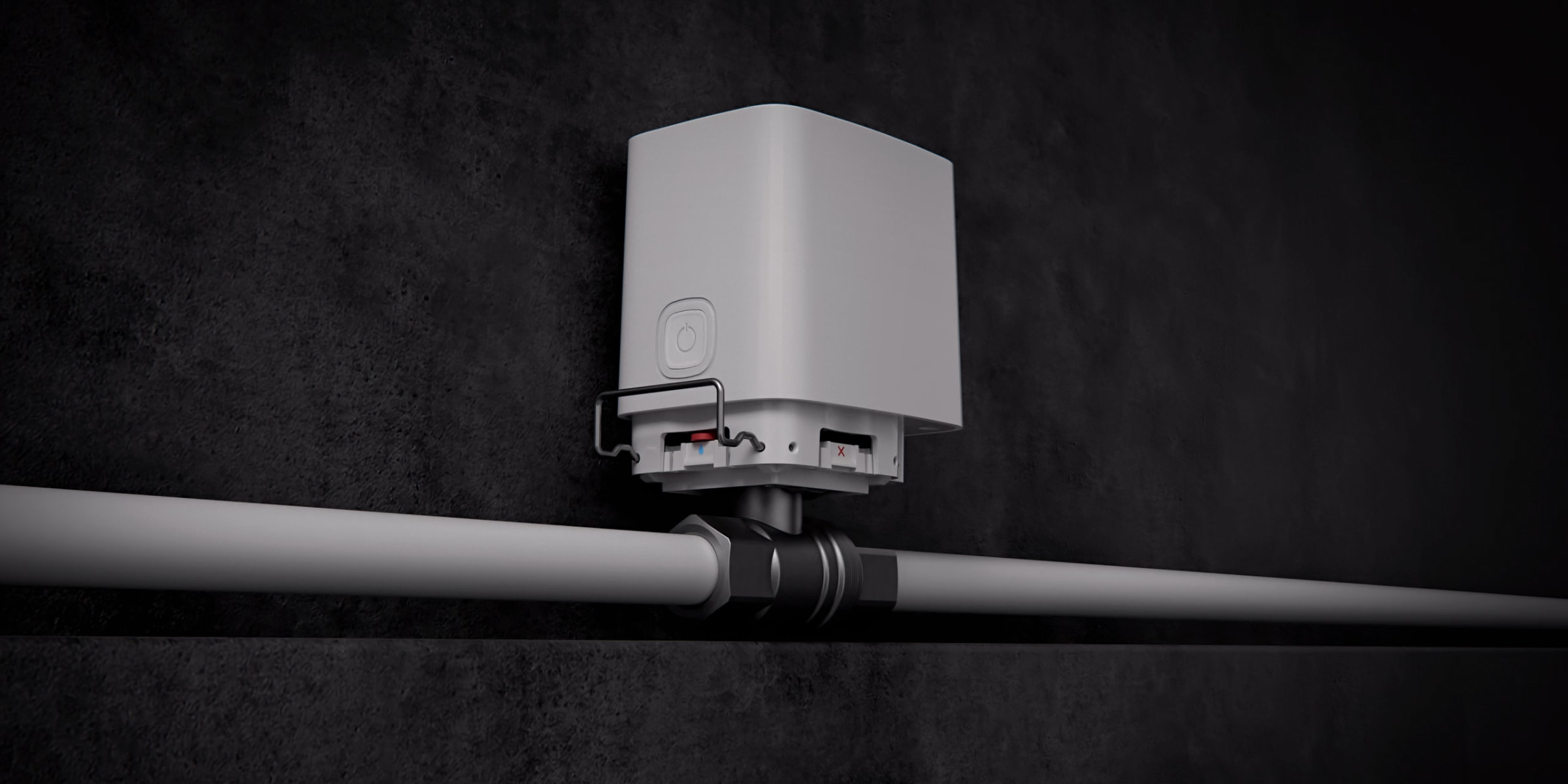
Installation
Before installing Ajax WaterStop, ensure that the optimal location of the device has been selected and that it complies with the requirements of this manual. When installing and operating the device, follow the general electrical safety rules for using electrical appliances and the requirements of electrical safety regulations.
Ajax WaterStop electric actuator can be installed on a bundled RuB valve and a third-party one. The electric actuator is compatible with valves that comply with the ISO 5211 standard. Therefore, a plumber can install a third-party ball valve one day, and an installer can fix an electric actuator and connect the device to the Ajax system another day.
Ajax WaterStop installation with bundled RuB valve
- Disassemble Ajax WaterStop:
- Remove the mounting locker.
- Remove the electric actuator from the shutoff valve mount.
- Shut off the water supply to the circuit where Ajax WaterStop will be installed.
- Install the bundled RuB valve on the pipeline.
- Select the installation option of the electric actuator on the mount. It can be installed on a mount with a rotation angle of 0, 90, 180, or 270 degrees.
Choose the installation angle so that Ajax WaterStop is easy to install and maintain.
To install an electric actuator with a rotation angle of 90 or 270 degrees, you should adjust the position of the stem rotated by the electric actuator coupling. Follow these steps:
- Remove the mounting platform from the shutoff valve using a hexagon (⌀ 3 mm) tool.
- Using a special tool or a flat-blade screwdriver, remove the circlip and then release the stem.
- Detach the lever from the mounting platform.
- Rotate the stem 90 degrees from the lever position.
- Place the lever on the mounting platform in its initial position (before removing the circlip).
- Reattach the circlip.
- Reinstall the mounting platform onto the shutoff valve.

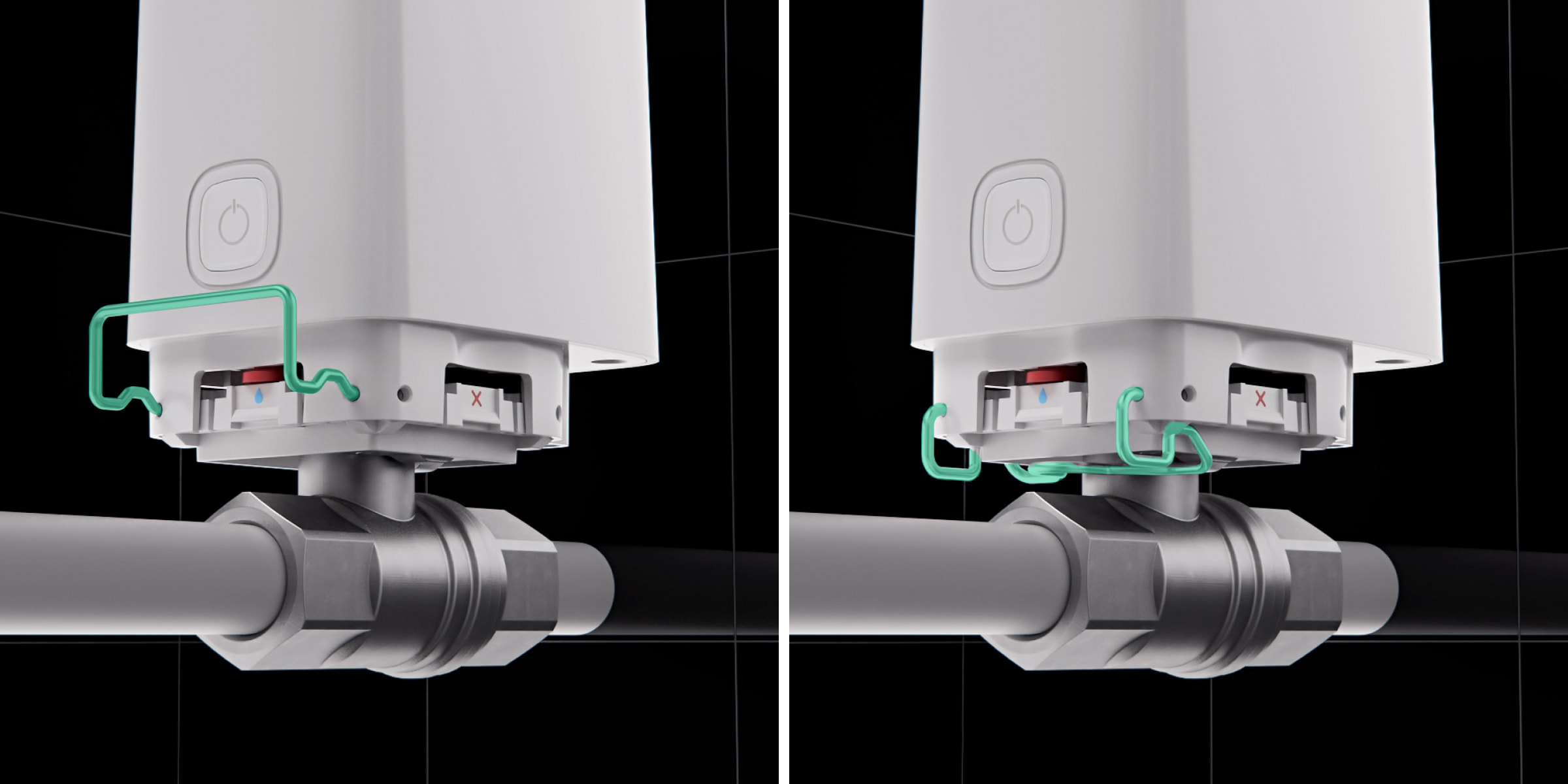
Ensure that Open position marks are always aligned along the pipeline.
- Place the removable part of the mounting platform on the necessary side. For the electric actuator with a rotation angle of 0 or 180 degrees, align with Open position marks. For 90 or 270 degrees, use Closed position marks.
- Ensure the lever on the mount and the electric actuator are in the same position. If the positions do not match, change the position of the key or the electric actuator coupling (by switching its position with the button on the enclosure).
The lever on the mount in the open position must always be directed along the pipeline.
- Install the actuator valve on the mount.
- Secure the actuator valve with the mounting locker.
- Standard locker allows quickly removing the electric actuator. Suitable for private houses, flats, or other non-public places.
- An anti-sabotage locker is suitable to complicate unauthorized disassembly of the electric actuator. Used in restaurants, laundries, factories, and other public or crowded places.
- Connect Ajax WaterStop to the hub.
- Resume water supply.
- Check the operability of Ajax WaterStop.
Ajax WaterStop installation with third-party shutoff valve
- Disassemble Ajax WaterStop:
- Remove the mounting locker.
- Remove the electric actuator from the shutoff valve mount.
- Remove the mount from the bundled shutoff valve using a hexagon (⌀ 3 mm).
- Shut off the water supply to the circuit where Ajax WaterStop will be installed.
- Install the third-party shutoff valve on the pipeline.
- Select the installation option of the electric actuator on the mount. It can be installed on a mount with a rotation angle of 0, 90, 180, or 270 degrees.
Choose the installation angle so that Ajax WaterStop is easy to install and maintain.
To install an electric actuator with a rotation angle of 90 or 270 degrees, you should adjust the position of the stem rotated by the electric actuator coupling. Follow these steps:
- Using a special tool or a flat-blade screwdriver, remove the circlip and then release the stem.
- Detach the lever from the mounting platform.
- Rotate the stem 90 degrees from the lever position.
- Place the lever on the mounting platform in its initial position (before removing the circlip).
- Reattach the circlip.
- Install the mount on the shutoff valve. Fix it to the valve with bundled fasteners.
Ensure that Open position marks are always aligned along the pipeline.
- Place the removable part of the mounting platform on the necessary side. For the electric actuator with a rotation angle of 0 or 180 degrees, align with Open position marks. For 90 or 270 degrees, use Closed position marks.
- Ensure the lever on the mount and the electric actuator are in the same position. If the positions do not match, change the position of the key or the electric actuator coupling (by switching its position with the button on the enclosure).
The lever on the mount in the open position must always be directed along the pipeline.
- Install the electric actuator on the mount.
- Secure the electric actuator with the mounting locker.
- Standard locker allows quickly removing the electric actuator. Suitable for private houses, apartments, or other non-public places.
- An anti-sabotage locker is suitable to complicate unauthorized disassembly of the electric actuator. Used in restaurants, laundries, factories, and other public or crowded places.
- Connect Ajax WaterStop to the hub.
- Resume water supply.
- Check the operability of Ajax WaterStop.
If, after installation, Ajax WaterStop cannot shut off the water, the mount is installed in the wrong position.
Connecting external power supply
Ajax WaterStop runs up to 3 years from the bundled batteries. The device is equipped with terminals connecting a third-party 7.5–14 V⎓, 1.8 A power supply unit. The recommended parameters of the external power supply are 9–12 V⎓, 2 A.Use a round 2 x AWG22 power cable with an external diameter of 3.0–3.7 mm to connect an external power supply.
When powered by the external power supply, Ajax WaterStop will turn on if it was turned off earlier.
The connection of the external power supply is recommended to avoid rapid discharge of batteries in the case of installation in places characterized by low temperatures or when frequent water shutoffs are reported.
When external power is connected, the pre-installed batteries are used as a backup power source. Do not remove them when connecting the power supply.
Before installing the device, be sure to check the insulation of the wires for damage. We recommend using a grounded power source. Do not disassemble the device under voltage. Do not use the device with a damaged power cable.
To connect external power supply:
- Shut off the water if necessary.
- Turn off Ajax WaterStop if it was on by holding the on/off button for 3 seconds.
- Pull out the mounting locker while holding the solenoid valve.
- Remove the electric actuator from the shutoff valve.
- Place the front side of the device with the Ajax logo on it on a soft cloth so as not to scratch the enclosure.
- Unscrew the protective plug on the bottom of the electric actuator enclosure using a hexagon (⌀ 3 mm).

- Loosen the screws with a PH1 cross-head screwdriver.

- Turn the electric actuator over while holding the front and back of the enclosure.
- Remove the front part of the electric actuator enclosure.
- Pass the de-energized power supply cable through the bundled sealing nut and silicone seal. The silicone seal is located in the electric actuator enclosure under the protective plug.
- Connect the cable to the terminals observing polarity. Polarity is marked on the plastic.

- Tighten the sealing nut on the bottom of the electric actuator enclosure (instead of the protective plug).
- Reinstall the front part of the device enclosure. The lid can be installed only in one (correct) position.
- Turn the device over while holding the front and back of the enclosure.
- Tighten the four screws with a PH1 cross-head screwdriver.
- Reinstall the electric actuator on the shutoff valve.
- Plug the power supply unit into an outlet.
- Turn on Ajax WaterStop, and check the status of batteries and external power in Ajax app and the overall operation of the device.
Adding to the system
Before adding a device
- Install the Ajax app.
- Log in to your account or create a new one.
- Select a space or create a new one.
The space functionality is available for apps of such versions or later:
- Ajax Security System 3.0 for iOS;
- Ajax Security System 3.0 for Android;
- Ajax PRO: Tool for Engineers 2.0 for iOS;
- Ajax PRO: Tool for Engineers 2.0 for Android;
- Ajax PRO Desktop 4.0 for macOS;
- Ajax PRO Desktop 4.0 for Windows.
- Add at least one virtual room.
- Add a compatible hub to the space. Ensure the hub is switched on and has internet access via Ethernet, Wi-Fi, and/or mobile network.
- Ensure the space is disarmed, and the hub is not starting an update by checking statuses in the Ajax app.
Only a PRO or a space admin with the rights to configure the system can add a device to the hub.
Connecting to the hub
Ajax WaterStop should be within the coverage area of the hub radio network to connect to the hub. To work via a radio signal range extender, it is necessary to pair the smart shutoff water valve to the hub and then connect it to the range extender (via settings).
The hub is incompatible with devices operating at different frequencies. The radio frequency range of the device may vary by region. It is recommended to buy and use Ajax devices in the same region. Please contact technical support for information on the operating frequency range.
Ajax WaterStop only works with one hub. When connected to a new hub, the smart water shutoff valve stops sending commands to the old one. Once added to a new hub, the smart water shutoff valve is not removed from the list of devices of the old hub. This must be done through Ajax app.
To connect Ajax WaterStop to a hub:
- Open Ajax app. Sign in to the account.
- If your account has access to more than one space or if you are using the PRO app, select the space to which you want to add the device.
- Go to the Devices
 menu. Press Add Device.
 - Give a name to the smart valve.
- Scan or enter the QR code (located on the device enclosure and its packaging).
- Select a virtual room and a security group (if the Group mode is enabled).
- Click Add Device — the countdown will begin.
If the maximum number of devices is added to the hub, when you try to add the smart valve in Ajax app, you will get a notification about exceeding the device limit. The maximum number of devices that can be connected to the hub depends on the central unit model.
- Turn on Ajax WaterStop by holding the power button for three seconds.
After a successful connection, Ajax WaterStop will appear in the list of hub devices. If connection fails, turn the device off and try again in 7 seconds. Refreshing the device statuses in the list depends on the Jeweller (or Jeweller/Fibra) settings. The default value is 36 seconds.
Icons
Icons display some of Ajax WaterStop states. Statuses can be checked in Ajax app in the Devices ![]() tab.
tab.
| Icon | Meaning |
|
Jeweller Signal Strength displays the signal strength between the hub and Ajax WaterStop. Recommended value is 2–3 bars. |
|
| The device is connected via a radio signal range extender. | |
|
Ajax WaterStop battery charge level. |
|
|
Ajax WaterStop is permanently deactivated. |
|
|
Ajax WaterStop has tamper-triggering events permanently deactivated. |
|
| Valve is stuck. | |
| Preventive maintenance is not configured. | |
| The device has lost connection with the hub or the hub has lost connection with the Ajax Cloud server. | |
|
The device has not been transferred to the new hub. |
States
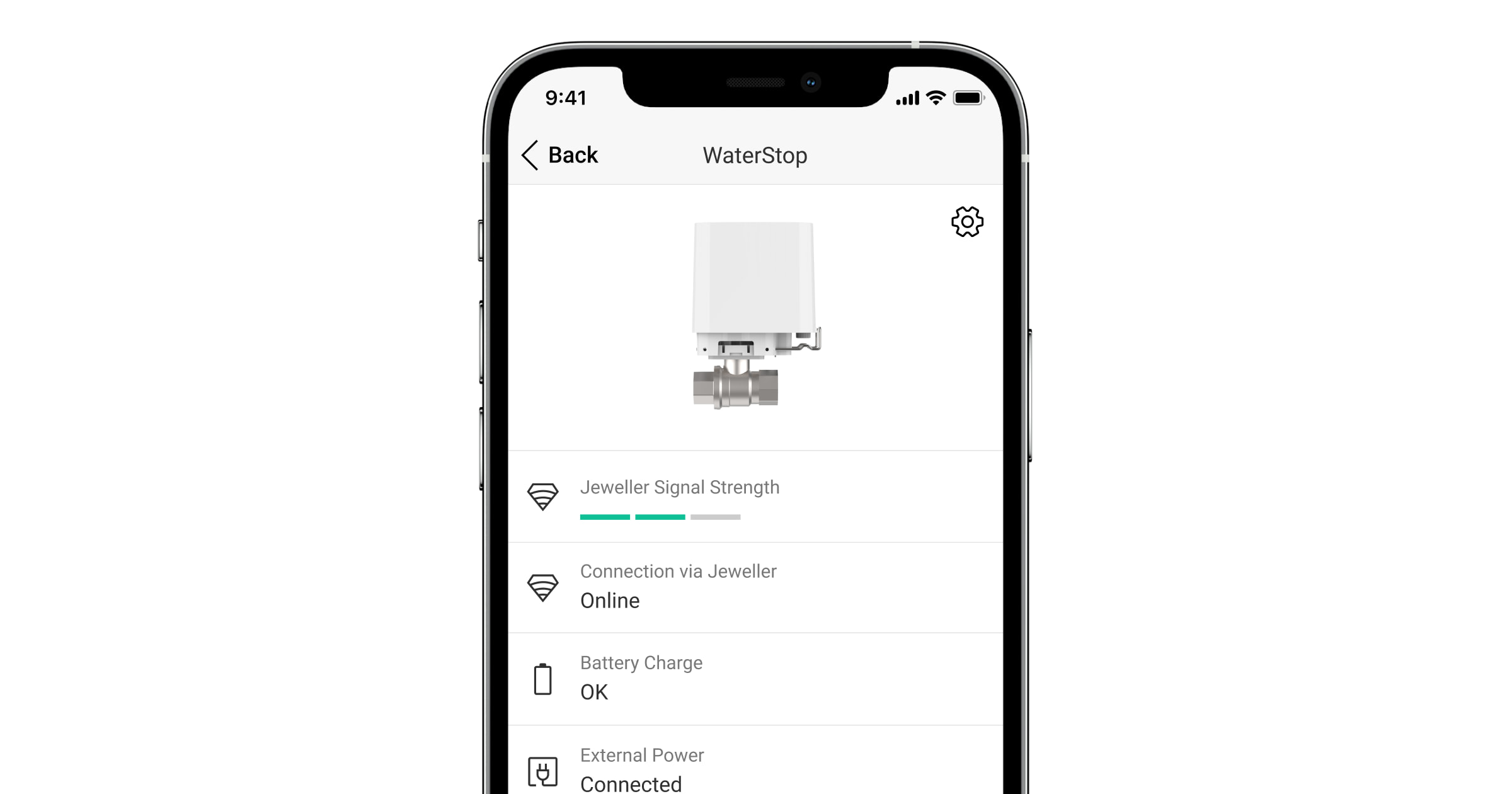
The states include information about the device and its operating parameters. Smart valve states are available in Ajax app. To see them:
- Open Ajax app.
- Select a space if you have several of them or using the PRO app.
- Go to the Devices tab.
- Select Ajax WaterStop in the list.
| Parameter | Meaning |
| Data import | Displays the error when transferring data to the new hub:
|
| Jeweller Signal Strength |
Signal strength between Ajax WaterStop and the hub (or the range extender) via the Jeweller channel. Recommended values: 2–3 bars. Jeweller is a protocol for the transmission of Ajax WaterStop events and alarms. |
| Connection via Jeweller | Connection status between Ajax WaterStop and hub (or range extender) via Jeweller channel:
|
| Battery Сharge | The battery charge level of the device:
When the batteries are low, Ajax apps and the security company receive appropriate notifications. We recommend replacing the batteries after receiving a low battery notification. When operating with dead batteries, we cannot guarantee that Ajax WaterStop will shut off or open the water valve. How the battery charge is displayed |
| External Power | Ajax WaterStop external power supply connection status:
|
| Lid | The status of the Ajax WaterStop tamper, which reacts to violations of the enclosure integrity or the removal of the electric valve from the ball valve:
|
| Water Supply | Ajax WaterStop ball valve status:
If you fail to turn the valve, the Water supply status (Open/Closed) is displayed in red, and an error notification icon |
| Preventive maintenance |
Available for devices with firmware version 5.60.1.64 or later, operating with hubs with OS Malevich 2.24 or later. Regular automatic procedure to prevent the shut-off valve from sticking:
|
| Lock Device Button | The ability to control the water supply using a button on the electric actuator enclosure:
|
| Permanent Deactivation | Shows the status of the device deactivation function:
|
| Firmware | Device firmware version. |
| Device ID | Device ID/serial number. Also available on the QR code on the device’s enclosure and the packaging. |
| Device No. | Device loop (zone) number. |
Settings
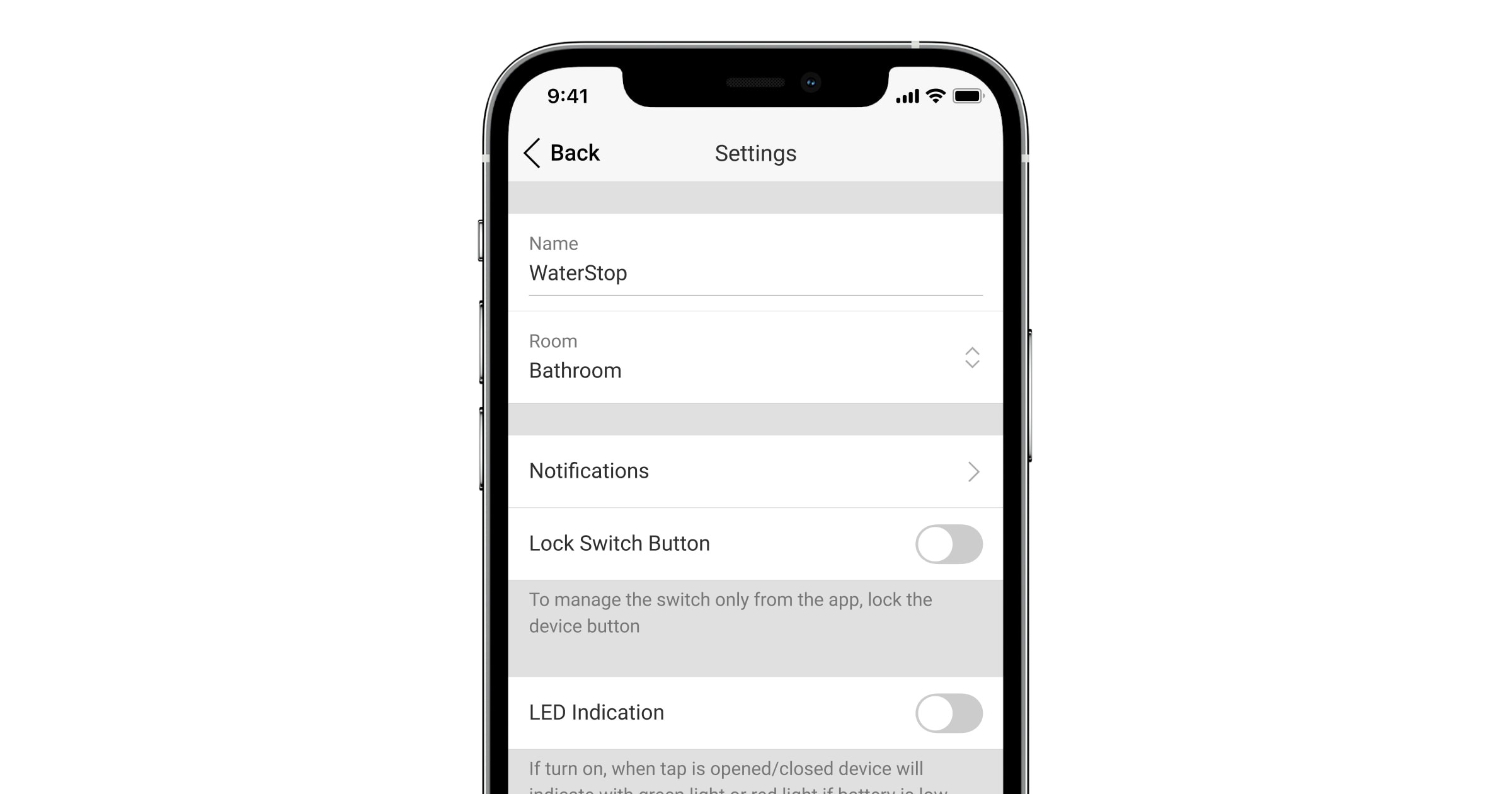
To change the smart valve settings in Ajax app:
- Open Ajax app.
- Select a space if you have several of them or using the PRO app.
- Go to the Devices tab.
- Select Ajax WaterStop in the list.
- Go to the Settings by clicking on the gear icon
 .
. - Set the required settings.
- Click Back to save the new settings.
| Settings | Meaning |
| Name |
Ajax WaterStop name. Displayed in the text of SMS and notifications in the event feed. To change the smart valve name, click on the text field. The name can contain up to 12 Cyrillic characters or up to 24 Latin symbols. |
| Room |
Selecting the virtual room to which Ajax WaterStop is assigned. The room name is displayed in the text of SMS and notifications in the events feed. To change the room, click on the field. |
| Notifications | Selecting the smart valve notifications:
The setting is available when Ajax WaterStop is connected to all hubs with firmware version OS Malevich 2.15 or higher and in apps of the following versions or higher:
|
| Preventive maintenance |
Available for devices with firmware version 5.60.1.64 or later, operating with hubs with OS Malevich 2.24 or later. Setting up the Ajax WaterStop preventive maintenance procedure. Available options:
|
| Lock device button |
Setting the water supply control using the button on the electric actuator enclosure. When this option is enabled, the water supply can be controlled only in Ajax apps as well as using automation scenarios. The option is disabled by default. |
| LED Indication | When this option is enabled, the LED indicates the Ajax WaterStop status. |
| Leakage response |
When the option is enabled, the system blocks reopening the valve when a leak is detected. The option is disabled by default. Do not use this feature with water fire suppression systems. The option is available on hubs with OS Malevich 2.36 and later, and if a leak detector is added to the system. |
| Scenarios |
Setting up Ajax WaterStop automation scenarios. |
| Jeweller signal strength test |
Switches Ajax WaterStop to the Jeweller signal strength test mode. The test allows checking the signal strength between the device and the hub or the range extender over the Jeweller wireless data transfer protocol to determine the optimal installation location for the device. |
| User manual | Opens the Ajax WaterStop User Manual in Ajax app. |
| Permanent deactivation |
Allows user to disable the device without removing it from the system. Three options are available:
|
| Delete device | Unpairs Ajax WaterStop from the hub and deletes its settings. |
Functionality testing
Ajax’s security system provides several tests to select the location of devices correctly. Ajax WaterStop tests do not start immediately, but the wait time does not exceed the duration of one “hub—detector” polling period (36 seconds at standard hub settings). The device polling period can be changed in the hub settings in the Jeweller (or Jeweller/Fibra) menu.
To run a test in Ajax app:
- Log in to your account in Ajax app.
- Select a space if you have several of them or using the PRO app.
- Go to the Devices menu.
- Select Ajax WaterStop.
- Go to Settings by clicking on the gear icon .
- Select Jeweller Signal Strength Test.
- Run and conduct the test using the prompts in the app.
Indication
| Indication | Event | Note |
| Lights up green for about 1.2 seconds. | Turning on the device. | |
| Lights up green for 3 seconds, then flashes red three times and goes out. | Turning off the device. | Press and hold the control button for more than 2 seconds to turn off the device. |
| Flashes green twice every 2 seconds. | The device is not connected to the hub. | Stops automatically after 60 seconds or by pressing the control button. |
| Lights up green for about 1 second. | Connecting the device to the hub. | |
| Slowly lights up green and goes out over 2 seconds. | Opening/closing a shutoff valve. | If LED Indication toggle is enabled. |
| Lights up green while the control button is pressed. | Pressing the control button. | If the control button is pressed for over 2 seconds, Ajax WaterStop will be turned off or on (depending on the initial state). |
| Lights up green for 1 second. | Tamper triggering. | |
| Flashes green three times every 1.7 seconds. | Low battery. | If LED Indication toggle is enabled. |
| Flashes red twice. | Rotation of the electric actuator is blocked. | Alert only appears after a failed actuator rotation attempt. |
| Flashes red five times every 3 seconds. | Battery malfunction. |
Malfunctions
If a malfunction is detected in Ajax WaterStop (for example, there is no connection with the hub or range extender), the malfunction counter is displayed in the device field in Ajax app.
Malfunctions are displayed in the shutoff valve States. Fields with malfunctions will be highlighted in red.
Malfunction is displayed if:
- Temperature protection was activated.
- There is no connection between Ajax WaterStop and the hub (or range extender).
- The Ajax WaterStop batteries are discharged.
- Valve is stuck.
Maintenance
Regularly check the operation of the device: check how Ajax WaterStop controls the water supply. The optimal frequency of checks is once every three months. Clean Ajax WaterStop enclosure from dust, cobwebs, and other contaminants as they emerge. Use a soft dry cloth suitable for equipment care. Do not use substances that contain alcohol, acetone, petrol, and other active solvents to clean the device.
We recommend turning on the Preventive maintenance feature or setting up a scheduled scenario to open and close a valve periodically. For example, once a week for one minute. This will protect the valve from getting stuck and extend its life.
Complete set
- Ajax WaterStop Jeweller.
- CR123A batteries (pre-installed) — 4 pcs.
- DN15 (½”), DN20 (¾”), or DN25 (1″) RuB shutoff valve (depends on the selected kit).
- Two mounting lockers: standard (pre-installed) and anti-sabotage.
- Sealing nut.
- Quick start guide.
Warranty
Warranty for the Limited Liability Company “Ajax Systems Manufacturing” products is valid for 2 years after the purchase.
If the device does not work correctly, first contact the support service. Technical issues can be resolved remotely in half of the cases.
Contact Technical Support:
