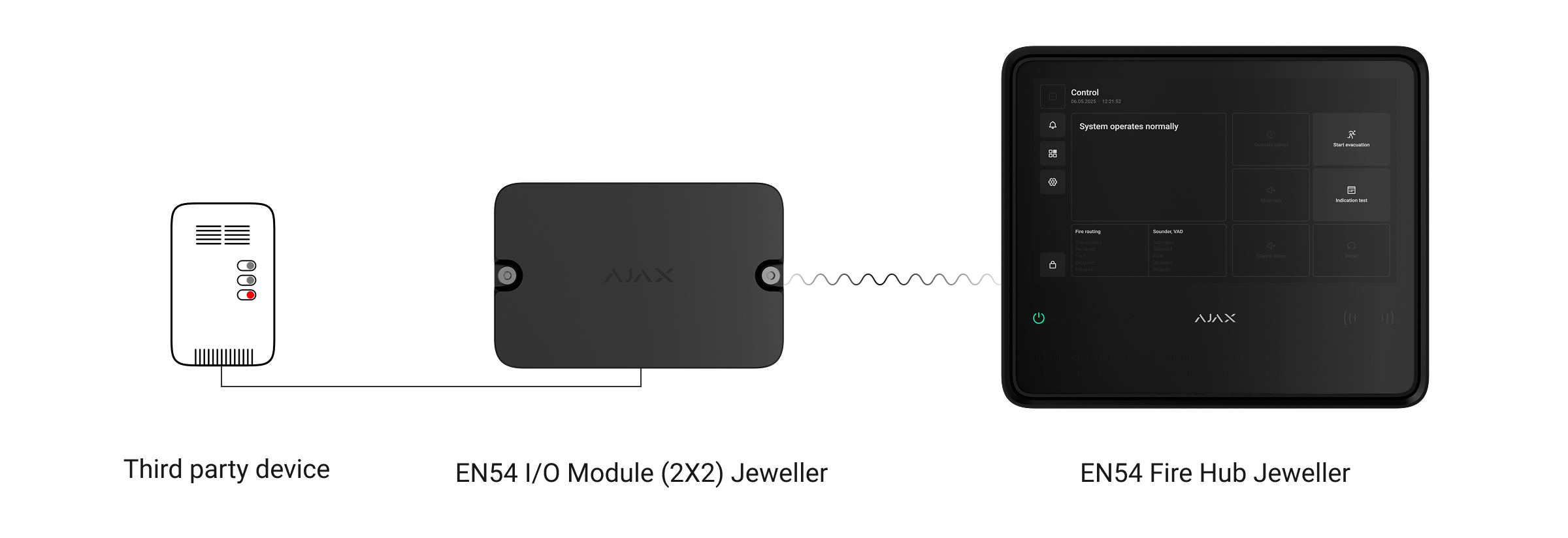
EN54 I/O Module (2X2) Jeweller is a wireless addressable module with two inputs and two outputs designed to integrate third-party wired devices into an Ajax system.
Its inputs can be used to receive signals from alarm and alert buttons, fire, smoke, temperature, carbon monoxide, and other wired detectors. The module’s outputs can be used to control automatic gates, door locks, emergency and escape lighting, and other life safety and firefighting equipment that can be controlled with relay outputs.
The integration module supports NC, NO, EOL, 2EOL, and 3EOL input connection types.
EN54 I/O Module (2X2) Jeweller operates as part of an Ajax system and communicates with the control and indicating equipment (CIE) via secure Jeweller radio protocol. The communication range with the CIE is up to 5,550 ft in an open space.
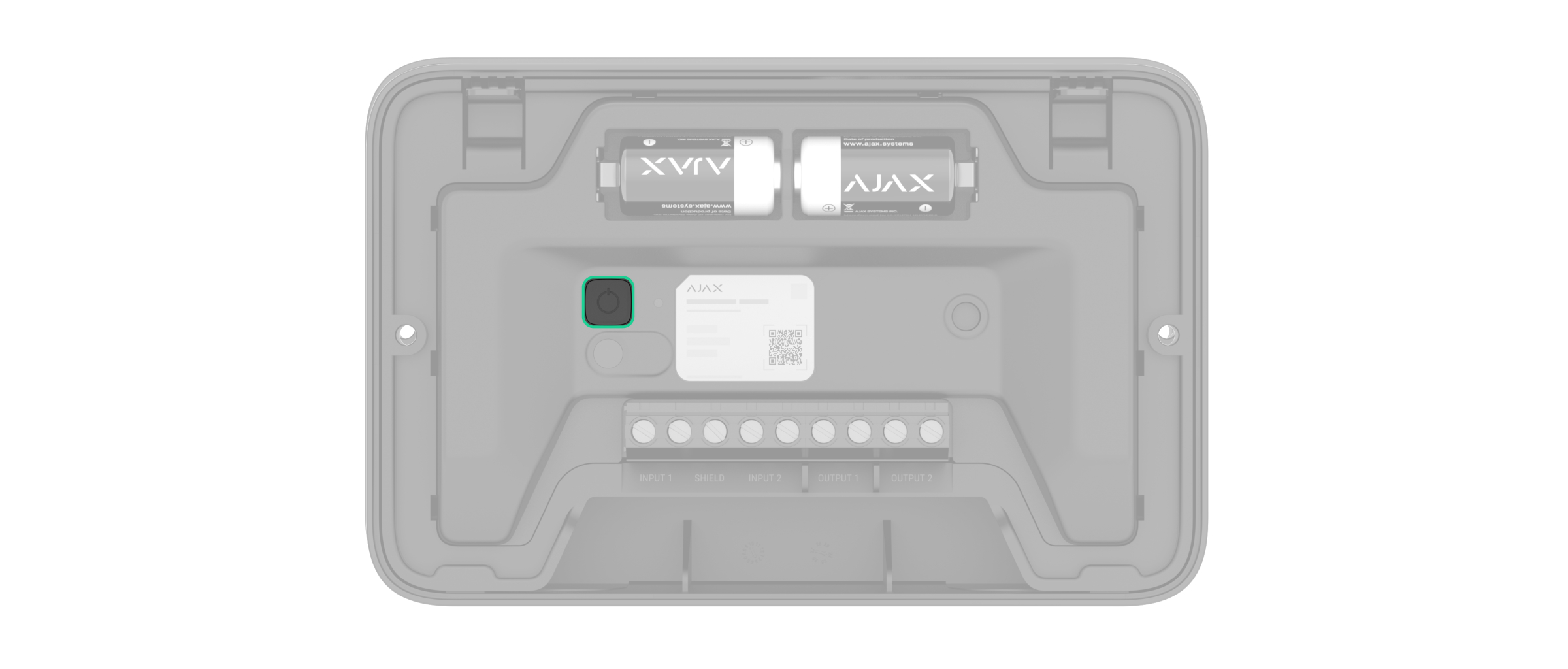
Functional elements
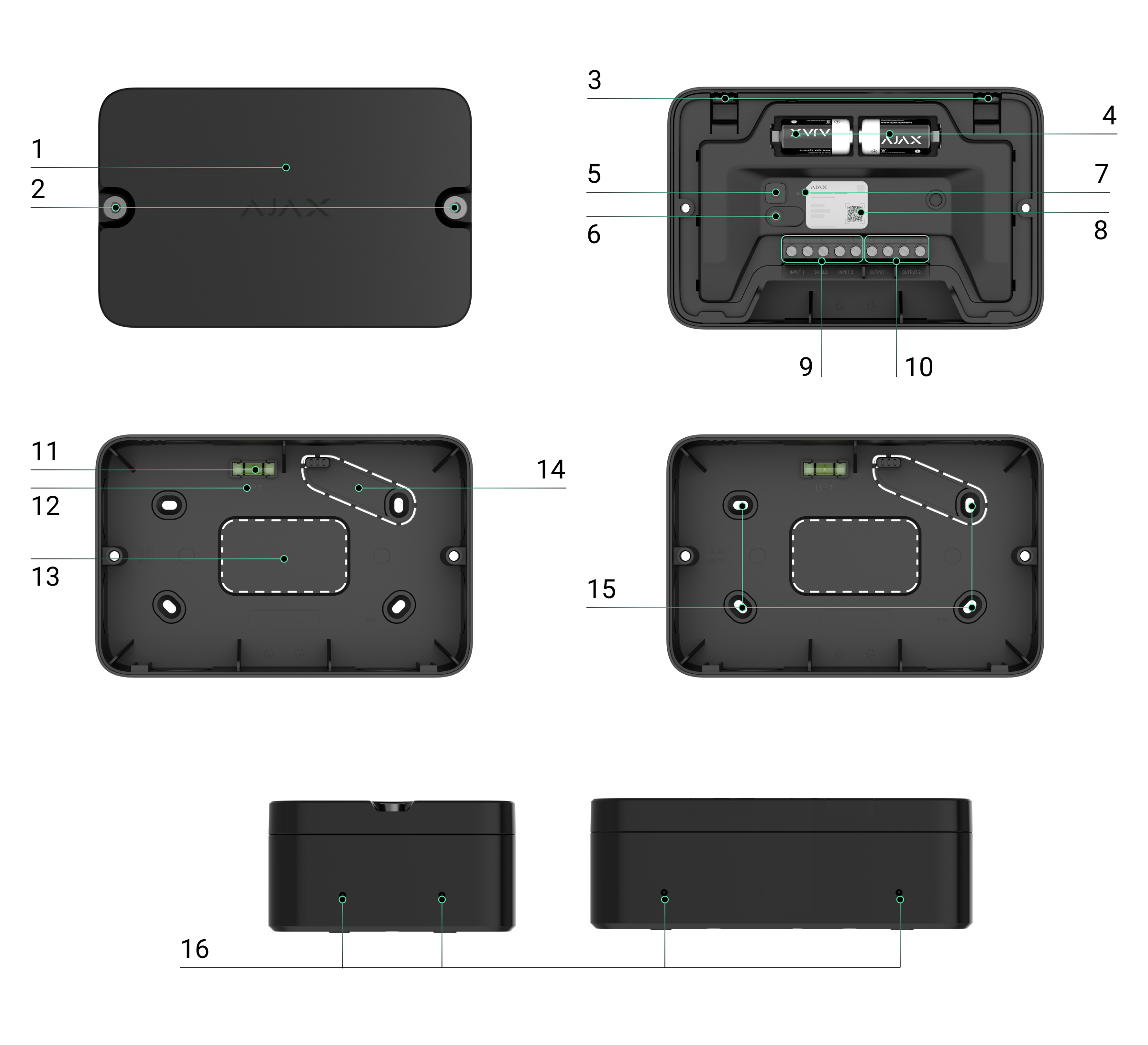
- Front lid of the module.
- Holding screws for securing the module’s front lid. They can be tightened or loosened with a bundled hex key (Ø 4 mm).
- Latches for securing the module in the casing.
- Two pre-installed CR123A batteries.
- Power button.
- Tamper button.
- LED indicator.
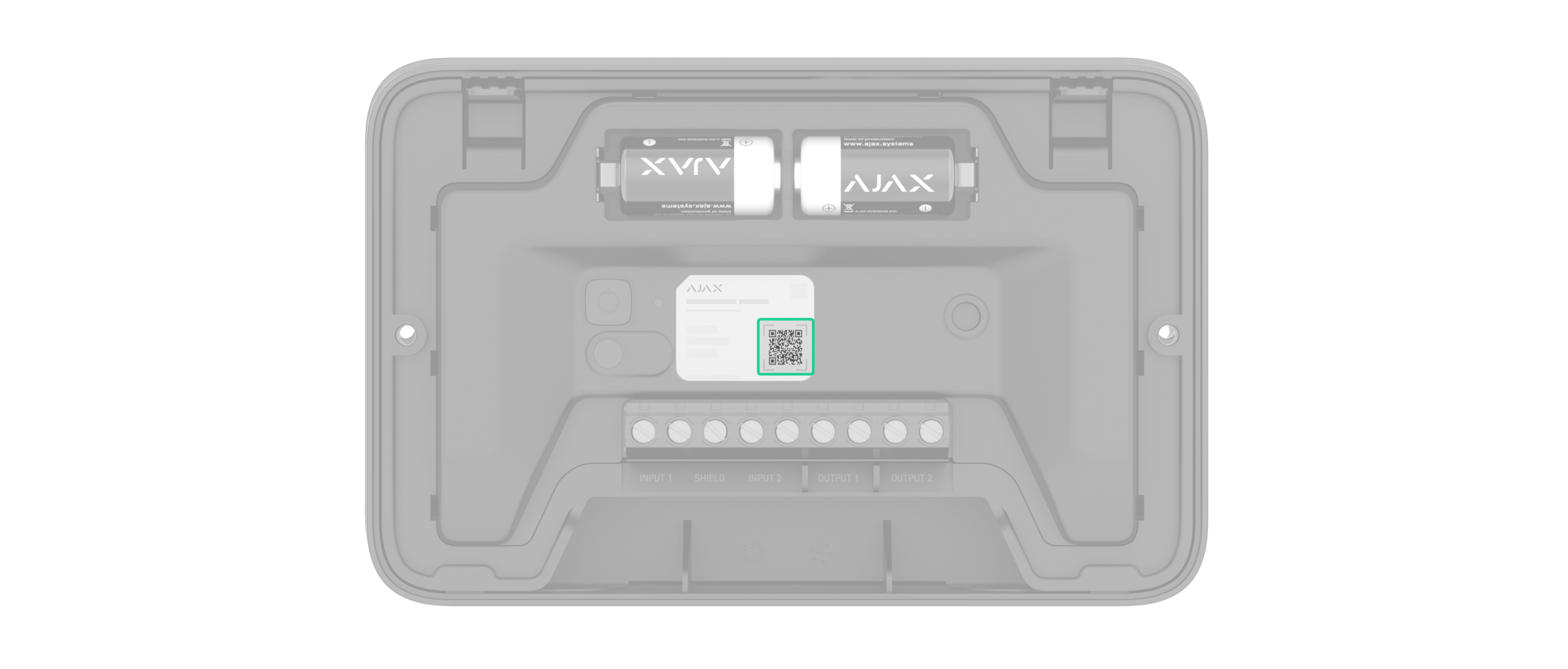
- QR code with the device ID. It is used to add the module to the CIE.
- Input terminals for connecting third-party devices.
- Relay output terminals for connecting third-party devices to the module’s relays.
- Bubble level to check the inclination angle of the module casing during installation.
- UP key, which marks the top of the module casing.
- Perforated part for running wires through the wall.
- Perforated part of the casing. It is used to trigger a tamper in case of any attempt to detach the module from the surface. Do not break it off.
- Holes for securing the module casing on the surface.
- Recesses for drilling holes up to Ø20 mm to route cables from the side. Each module side has two recesses.
Compatible CIEs and range extenders
The module requires the Ajax CIE with an up-to-date OS Malevich version.
Operating principle
EN54 I/O Module (2X2) Jeweller is designed to integrate up to 4 third-party wired devices into an Ajax system. The module receives state data from two input devices and controls two output devices with relays with potential-free dry contacts.
The module is powered by pre-installed batteries and does not require an external power supply. EN54 I/O Module (2X2) Jeweller monitors its operational state and informs the system of faults if any occur.
Inputs
With EN54 I/O Module (2X2) Jeweller, it is possible to integrate third-party input devices into an Ajax system. These include manual call points (conventional), sprinkler flow switches, magnetic door contacts, beam smoke detectors, elevator control panels, fan or HVAC control relays, and others.
To connect input devices, use the terminals:
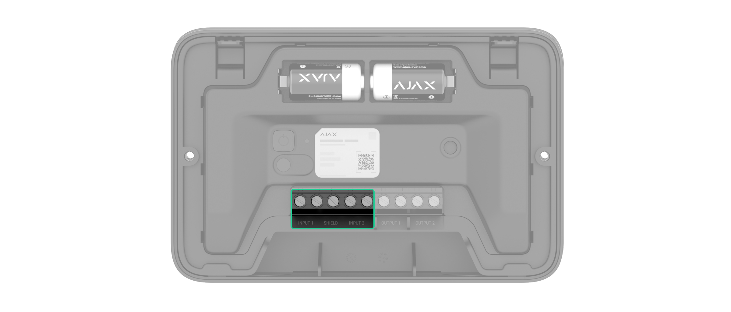
- Input 1 — input terminals for connecting the first wired device.
- Shield — common input for connecting the shield of the cables that connect third-party wired devices.
- Input 2 — input terminals for connecting the second wired device.
Note that EN54 I/O Module (2X2) Jeweller can not supply power to the connected devices. If necessary, provide the power supply to such devices according to their manufacturer’s requirements.
Connection types of wired input devices:
- Without EOL
- EOL
- 2EOL
- 3EOL
In an Ajax app, you can configure the event type and default state (normally open or normally closed) for each sensor of the wired input, as well as the resistance values if an EOL connection is used. This allows you to connect any detector with potential-free dry contacts to the module.
The selected event type determines the text of alarm notifications and events of the connected device, as well as event codes transmitted to the monitoring software.
Event types of wired input devices
| Event type | Icon | Meaning |
| Fire alarm |
 |
Alarm in case the device detects a fire. |
| Device fault |
 |
Event caused by the device fault. |
| Tamper fault |
 |
Fault in case the device tamper button is triggered. |
| Evacuation |
 |
Evacuation signal in case of fire hazard. |
| Custom |
 |
User-defined event. Custom events are not sent to the monitoring software. |
| Auxiliary alarm |
 |
Notification of the need for medical or other urgent help. |
| Panic button |
 |
Urgent notification of a threat to personal or property safety. |
| Gas alarm |
 |
Notification of a potential gas leak. |
| Leakage |
 |
Leakage notification to minimize potential property damage. |
Outputs
With EN54 I/O Module (2X2) Jeweller, it is possible to control third-party output devices. These include fire door release mechanisms, elevator control systems, fan shutoff or damper control relays, emergency lighting circuits, remote mimic panels, and other life safety and firefighting devices.
Both relays must be installed in the electrical circuit gap to control the power supply of electrical appliances connected to this circuit. The relays are configured and controlled separately.
The operating ranges of each relay output are described in the technical specifications.
To connect to the relays, use the terminals:
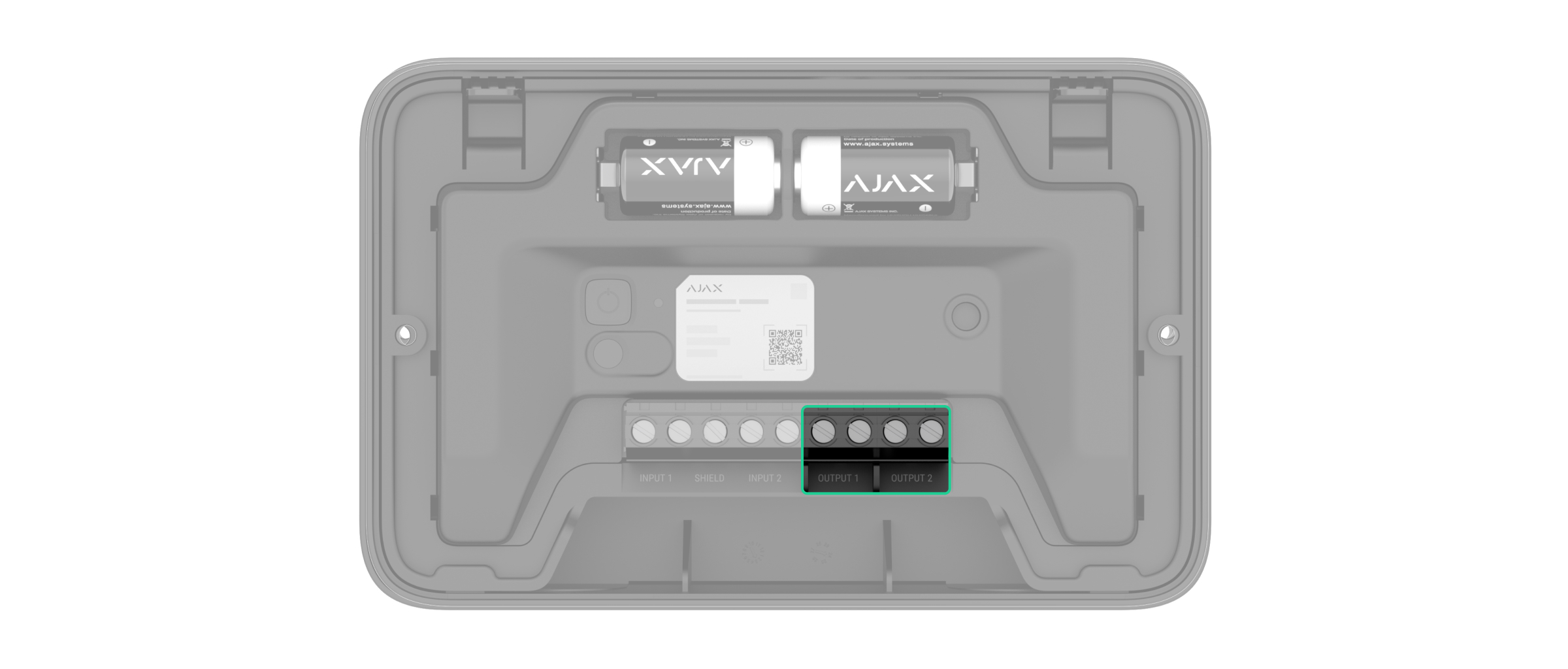
- Output 1 — two output terminals of the first relay.
- Output 2 — two output terminals of the second relay.
Note that EN54 I/O Module (2X2) Jeweller can not supply power to the connected devices. If necessary, provide the power supply to such devices according to their manufacturer’s requirements.
When connecting a third-party wired device to the relay output terminals, you can select the terminal state for this device, namely normally closed or normally open, in an Ajax app.
Each output device can be controlled manually via Ajax apps or the CIE touch screen.
Also, the module has the Fail-safe mode feature for outputs. When the mode is enabled, the module automatically activates the connected devices in case of any fault, such as when the module is offline, discharged, or malfunctioning. The devices remain activated until the fault is resolved.
Jeweller data transfer protocol
Jeweller is a wireless data transfer protocol that provides fast and reliable two-way communication between the CIE and devices. The module uses Jeweller to transmit commands, alarms, and events.
Sending events to the monitoring station
An Ajax system can transmit alarms to both the Ajax PRO Desktop app and the monitoring station in the formats of SurGard (Contact ID), SIA (DC-09), ADEMCO 685, and other protocols.
EN54 I/O Module (2X2) Jeweller can transmit the following events:
- Module fault.
- Tamper alarm/recovery.
- Events and alarms of connected input devices.
- Loss/recovery of communication between EN54 I/O Module (2X2) Jeweller, connected input devices, and the CIE.
- Short circuit or damage to the line connecting third-party input devices to EN54 I/O Module (2X2) Jeweller (for EOL connections).
When an alarm is received, the monitoring station operator knows precisely what happened and where. The addressability of Ajax devices allows for sending events to Ajax PRO Desktop or the monitoring software, including the device type, its name, fire zone, virtual room, and location description. Note that the list of transmitted parameters may vary depending on the monitoring software and the selected communication protocol for the monitoring station.
You can find the device ID and zone number in the device states.
Selecting the installation site
Follow your local fire safety regulations when selecting the module installation site.
It is advisable to choose an installation site where EN54 I/O Module (2X2) Jeweller is hidden from prying eyes — for example, in a back room. This will help reduce the likelihood of system sabotage. Note that the device is intended for indoor installation only.
When choosing where to place EN54 I/O Module (2X2) Jeweller, consider the parameters that affect its operation:
Consider the placement recommendations when developing a system project. Only specialists may design and install Ajax systems. A list of recommended partners is available here.
Signal strength
The signal strength is determined by the number of undelivered or corrupted data packages over a certain period of time. The icon ![]() in the Devices
in the Devices ![]() tab in Ajax apps indicates the signal strength:
tab in Ajax apps indicates the signal strength:
- three bars — excellent signal strength;
- two bars — good signal strength;
- one bar — low signal strength, stable operation is not guaranteed;
- crossed-out icon — no signal.
Note that if the signal strength is excellent, the device can automatically adjust the radio transmission power to reduce power consumption and radio interference.
Run the Jeweller signal strength test before final installation. The test checks the signal strength at the device’s maximum transmission power. For the device to comply with the EN 54 requirements, the signal strength between the device and the CIE must be three bars.
If the test shows the signal strength of one or zero bars, we do not guarantee the module will operate stably. Consider relocating the module, as adjusting its position even by 8 inches or changing its orientation relative to the CIE can significantly improve the signal strength. If the signal remains poor or unstable after relocation, consider using an Ajax radio signal range extender.
Refer to the Module functionality test section to learn how to run the Jeweller signal strength test.
Where not to install the module
- In places where temperature and humidity levels are outside the permissible limits. This can damage the module.
- In places with low or unstable Jeweller signal strength. This may result in losing connection to the CIE.
- Outdoors.
- Closer than 3 ft to the CIE or an Ajax radio signal range extender.
Preparing for installation
Cable arrangement
When preparing to lay cables, read the electrical and fire safety regulations in your area. Strictly follow these standards and regulations.
Cable specifications for input and output devices
We recommend using fire-resistant cables that comply with the fire safety regulations applicable in your region.
Wires with a conductor cross-sectional area of 0.4–2.5 mm² (21–13 AWG) can be connected to the module terminals.
The maximum cable length for connecting third-party devices to EN54 I/O Module (2X2) Jeweller is 325 ft if 2×1.5 mm² (16 AWG) fire-resistant cable is used. However, the maximum length may vary depending on the cable type and requirements of the third-party device manufacturer.
To check specific cable requirements, refer to the user manual of the device that will be connected to the module.
Cable routing
The EN54 I/O Module (2X2) Jeweller casing allows wires to be routed from the back, side, top, or bottom.
To route the cable from the back, you can use the central hole highlighted in the picture.
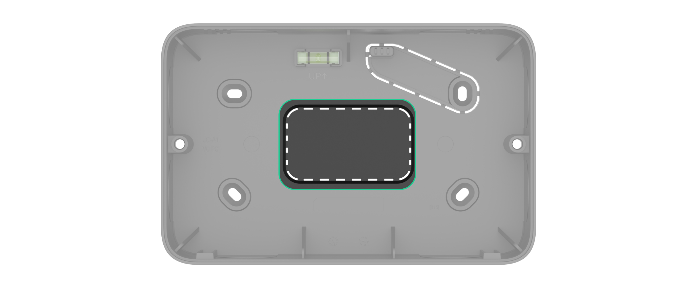
To route the cable from the side, top, or bottom, you can drill holes following the recesses on the module casing, considering the size of cable glands. There are two recesses on each side of the module. We recommend using a hole saw for plastic up to Ø20 mm.
Also, consider that the front lid of the module can be rotated 180° during installation.
Preparing cables for connection
Remove the insulating layer and strip the cable with a special insulation stripper. The wire ends inserted into the device terminals must be tinned or crimped with a sleeve. This ensures a reliable connection and protects the conductor from oxidation.
To check specific cable preparation requirements, refer to the user manual of the device that will be connected to EN54 I/O Module (2X2) Jeweller. Follow these requirements to ensure stable operation of the device.
Installation
Before installing EN54 I/O Module (2X2) Jeweller, ensure you have selected the optimal location that complies with the requirements of this manual.
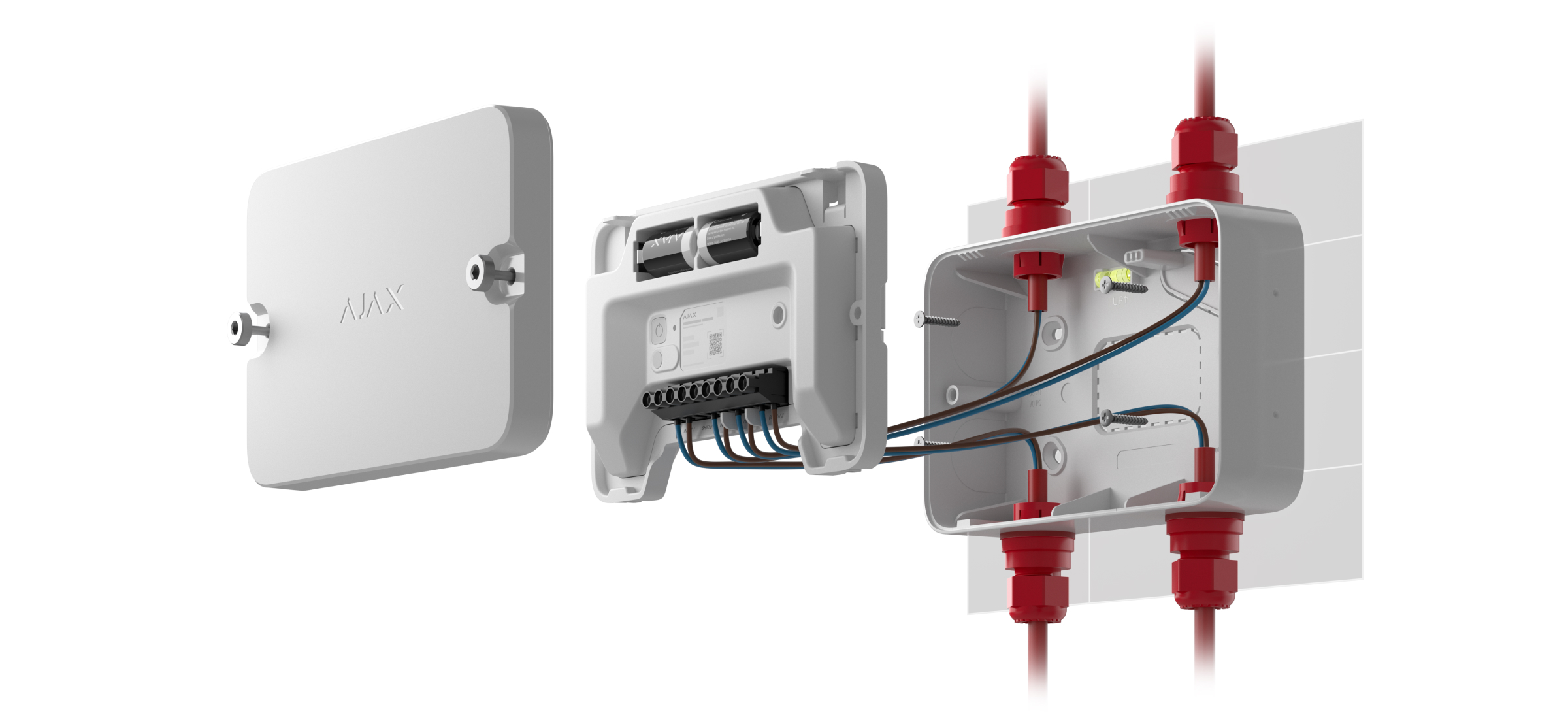
To install the module:
- De-energize the cables you will connect to EN54 I/O Module (2X2) Jeweller.
- Unscrew the module’s front lid and remove it.
- Remove the module from its casing by pushing the latches down and pulling the module.
- Prepare the holes for routing the cables in the casing. Refer to the Cable routing section for all options.
- Insert the cable glands into the prepared holes in the module casing if necessary.
- Run the cables into the module casing through the holes made.
- Using all fixing points, secure the module casing on the surface at the selected installation site with the bundled screws. One of these points is located in the perforated part above the tamper button and is required for it to trigger if someone attempts to detach the module.
- Connect the wires to the third-party device terminals and to the corresponding module terminals. The wiring diagram can be found in the user manual provided by the manufacturer of the wired device. Ensure the polarity and wire connection order are correct. Firmly secure the cable to the terminals.

Before connecting the device to EN54 I/O Module (2X2) Jeweller, carefully read the manufacturer’s instructions.
- Install the module in the casing. Slightly push each latch until it is securely attached to the casing.
- Add EN54 I/O Module (2X2) Jeweller to the CIE.
- Install the front lid on the module and fasten it with the bundled screws. The front lid can be rotated 180° during installation.
- Switch on the power of the wired devices if necessary.
- Add wired input and output devices to the system.
- Run the module functionality test.
Adding to the system
The CIE and the device must operate on the same radio frequency; otherwise, they are incompatible. The radio frequency range of the device may vary depending on the region. We recommend purchasing and using Ajax devices in the same region. You can verify the range of operating radio frequencies with the technical support service.
Before adding the module
- Install an Ajax app.
- Log in to your account or create a new one.
- Select a space or create a new one.
- Add at least one virtual room.
- Add a compatible CIE to the space. Ensure the CIE is switched on and has internet access via Ethernet, Wi-Fi, and/or mobile network.
- Check the states in the Ajax app to ensure the space is disarmed and the CIE is not starting an update.
Only a PRO or a space admin with the rights to configure the system may add the device to the CIE.
Adding the module to the CIE
- Open an Ajax app. Select a space to which you want to add the device.
- Go to the Devices
 tab and tap Add device.
 - Scan the QR code or enter the device ID manually. A QR code with ID is placed on the device under the front lid. Also, it is duplicated on the device packaging.
- Assign a name to the device.
- Select a fire zone and a virtual room.
- If necessary, specify the device location in the Location field.
- Tap Add device, and the countdown will begin.
- Switch on the device by holding the power button for 3 seconds.
Once added to the CIE, the device will appear in the list of CIE devices in the Ajax app. The device state update interval depends on the Jeweller settings and is 36 seconds by default.
If the connection fails, try again in 5 seconds. If the maximum number of devices has already been added to the CIE, an error notification will appear when you try to add more.
EN54 I/O Module (2X2) Jeweller works with only one CIE. When added to a new CIE, the module stops sending events to the old CIE. After the module is added to the new CIE, it will not be automatically removed from the device list of the old CIE. This must be done through the Ajax app.
Adding a connected wired input device
In an Ajax system, each device connected to EN54 I/O Module (2X2) Jeweller occupies one slot within the CIE’s device limit.
- In an Ajax app, go to the Devices tab.
- Find EN54 I/O Module (2X2) Jeweller in the list.
- Select Devices under the module icon.
- Tap Add device.
- Assign a name to the device.
- Select the wired input to which the device is physically connected.
- Select a fire zone and a virtual room.
- If necessary, specify the device location in the Location field.
- Tap Add device. The device will be added within 30 seconds.
The device state update interval depends on the Jeweller settings; the default value is 36 seconds.
If the connection attempt fails, ensure the wired connection is correctly set up before trying again. If the maximum number of devices has already been added to the CIE, an error notification will appear when you try to add another device.
Adding a connected wired output device
To add the wired output device to the module, enable this device in the module settings.
- Go to the Devices tab.
- Select EN54 I/O Module (2X2) Jeweller from the list.
- Go to Settings
 .
. - Select the relay output to which the device is physically connected.
- Assign a name to the device.
- Specify the type of the device connected to the output.
- Configure the required relay output settings.
- Tap Save to save the settings.
Module functionality test
An Ajax system provides several types of tests to help select the correct installation place for the devices. For EN54 I/O Module (2X2) Jeweller, the following test is available:
- Jeweller signal strength test — to determine the signal strength and stability between the CIE (or the radio signal range extender) and the module via the wireless Jeweller data transfer protocol at the device installation site.
Control via the app
In Ajax apps, a user can switch on/off electrical appliances connected to an electrical circuit controlled by EN54 I/O Module (2X2) Jeweller relay outputs. Turn on/off the relay output toggle in the EN54 I/O Module (2X2) Jeweller field in the Devices ![]() tab — the relay output state will change to the opposite, and the connected electrical device will switch on or off.
tab — the relay output state will change to the opposite, and the connected electrical device will switch on or off.
Quick control of automation devices is also available in the Automation menu. You can open the menu in Ajax apps:
- Go to the Control
 tab.
tab. - Swipe up.
- Control the required devices.
- Swipe down to return to the Control tab.
Icons
Icons in an Ajax app display some of the EN54 I/O Module (2X2) Jeweller states. You can check the icons in the Devices ![]() tab.
tab.
Module icons
| Icon | Meaning |
|
Jeweller signal strength. It displays the signal strength between the CIE and the device. The recommended value is 3 bars. |
|
|
Battery charge level of the device. |
|
|
The device operates via the radio signal range extender. |
|
| The module is being tested. | |
| EN54 I/O Module (2X2) Jeweller has a fault. The list of faults is available in the module states. | |
| EN54 I/O Module (2X2) Jeweller is disabled. | |
| The device has lost connection to the CIE, or the CIE has lost connection to the Ajax Cloud server. | |
|
The device has not been transferred to a new CIE. |
Icons of connected input devices
| Icon | Meaning |
| The connected device has detected a fire. | |
| The connected device is being tested. | |
| The connected input device has a fault. The list of faults is available in the states of connected input devices. | |
| The connected input device is disabled. |
States
Module states
The states include information about the module and its operating parameters. You can find the states of EN54 I/O Module (2X2) Jeweller in Ajax apps:
- Go to the Devices tab.
- Select EN54 I/O Module (2X2) Jeweller from the list.
| Parameter | Meaning |
| Fault |
The module has a fault. Tapping on The field is displayed only if a fault is detected. |
| Disabled |
The module or some of its functions are disabled. It does not respond to the alarm and does not notify users and the monitoring station. Tapping on The field is displayed only if the module is completely or partially disabled. |
| Temperature | The module temperature. It is measured by EN54 I/O Module (2X2) Jeweller and changes depending on the ambient temperature. |
| Jeweller signal strength |
Jeweller signal strength between the module and the CIE (or the range extender). The recommended value is 3 bars. Jeweller is a protocol for transmitting commands, events, and alarms. |
| Connection via Jeweller | Connection state via Jeweller channel between the module and the CIE (or the range extender):
|
<Range extender name> |
Connection state between the module and the radio signal range extender.
The field is displayed if the module operates via the radio signal range extender. |
| Battery charge | The battery charge level of the module. Two states are available:
When the batteries need to be replaced, users and the monitoring company will receive appropriate notifications. |
| Lid | State of the tamper button that is triggered when the module is detached from the surface or the integrity of the casing is compromised:
|
| Relay state | State of the relays:
This state is displayed for each relay. If the relay is not set up, its status is not displayed, and the relay is not displayed in the module list and the Automation menu. |
| Fire zone | Number and name of the fire zone to which the module is assigned. |
| Room | Name of the room to which the module is assigned. |
| Location | Detailed description of the module location. |
| Firmware | Module firmware version. |
| Device ID | EN54 I/O Module (2X2) Jeweller ID. It is also available on the module behind the front lid and on its packaging. |
| Device No. | Number of the device loop (zone). |
States of connected input devices
The states display information about the input devices and their operating parameters. You can find the states of the devices connected to EN54 I/O Module (2X2) Jeweller in Ajax apps:
- Go to the Devices tab.
- Find EN54 I/O Module (2X2) Jeweller in the list.
- Select Devices under the EN54 I/O Module (2X2) Jeweller icon.
- Select the device from the list.
| Parameter | Meaning |
| Alarm |
The wired device has detected a fire. Tapping on The field is displayed only if a fire is detected. |
| Fault |
The wired device has a fault. Tapping on The field is displayed only if a fault is detected. |
| Disabled |
The wired device is disabled. Tapping on The field is displayed only if the wired device is disabled. |
| I/O module connection state | Connection state on the line between EN54 I/O Module (2X2) Jeweller and the connected wired device:
|
| Type of event | State of the connected wired device sensor:
Number of Type of event fields corresponds to the number of sensors for one wired device and depends on the Input type setting. |
| Fire zone | Number and name of the fire zone to which a wired device is assigned. |
| Room | Name of the room to which the device is assigned. |
| Location | Detailed description of the device location. |
| Wire input | Number of the EN54 I/O Module (2X2) Jeweller zone to which a wired device is connected. |
| Device No. | The device loop (zone) number. |
Settings
Module settings
To change EN54 I/O Module (2X2) Jeweller settings, in an Ajax app:
- Go to the Devices tab.
- Select EN54 I/O Module (2X2) Jeweller in the list.
- Go to Settings .
- Configure the required settings.
- Tap Back to save the new settings.
| Settings | Meaning |
| Name |
Name of the module. It is displayed in the list of CIE devices and in the text of SMS and notifications in the event feed. To change the name, tap on the text field. The name can contain up to 24 Latin characters or up to 12 Cyrillic characters. |
| Fire zone |
Selecting the fire zone to which EN54 I/O Module (2X2) Jeweller is assigned. The fire zone is displayed in the text of SMS and notifications in the event feed. |
| Room |
Selecting the virtual room to which EN54 I/O Module (2X2) Jeweller is assigned. The room name is displayed in the text of SMS and notifications in the event feed. |
| Location |
Detailed description of the device location. It is displayed next to the room name in the event feed notifications. The location field can contain up to 24 Latin or Cyrillic characters. |
| Relay outputs |
Opening the settings menu of the corresponding relay output. |
| Notify about tamper faults | Selecting when to receive notifications about the lid state:
|
| Jeweller signal strength test |
Switching the device to the Jeweller signal strength test mode. The test allows you to check the signal strength between the CIE (or the radio signal range extender) and the device via the wireless Jeweller data transfer protocol to select the optimal installation site. |
| Device disablement |
The option allows you to deactivate the device outputs. The device remains in the system but does not activate the disabled output in response to any trigger. |
| User guide | Opening the EN54 I/O Module (2X2) Jeweller user manual in an Ajax app. |
| Delete device | Unpairing the module, disconnecting it from the CIE, and deleting its settings. |
Relay output settings
| Settings | Meaning |
| Output device | Selecting the type of the device connected to the output:
|
| Name |
Name of the relay output. It is displayed in the module settings and in the text of SMS and notifications in the event feed. To change the output name, tap on the text field. The name can contain up to 24 Latin characters or up to 12 Cyrillic characters. |
| Contact state | Selecting the normal state of the relay contacts:
|
| Fail-safe mode | When the mode is enabled, the module automatically activates the connected devices in case of any fault (the module is offline, discharged, or malfunctioning). The devices remain activated until the fault is resolved. |
Settings of connected input devices
To change the connected device settings, in an Ajax app:
- Go to the Devices tab.
- Find EN54 I/O Module (2X2) Jeweller in the list.
- Select Devices under the EN54 I/O Module (2X2) Jeweller icon.
- Select the device from the list.
- Go to Settings .
- Configure the required settings.
- Tap Back to save the new settings.
The list of wired input device settings changes depending on the Input type parameter (Without EOL, EOL, 2EOL, 3EOL).
| Setting | Meaning |
| Name |
Name of the wired device. It is displayed in the list of CIE devices and in the text of SMS and notifications in the event feed. To change the name, tap on the text field. The name can contain up to 24 Latin characters or up to 12 Cyrillic characters. |
| Fire zone |
Selecting the fire zone to which the wired input device is assigned. The fire zone is displayed in the text of SMS and notifications in the event feed. |
| Room |
Selecting the virtual room to which the device is assigned. The room name is displayed in the text of SMS and notifications in the event feed. |
| Location |
Detailed description of the device location. It is displayed next to the room name in the event feed notifications. The location field can contain up to 24 Latin or Cyrillic characters. |
| Input type | Selecting the connection type of a third-party input device:
|
| Sensor 1 |
Selecting the Type of event and Default state parameters for Sensor 1. The Type of event option allows you to select the event type for the sensor of the wired device that is transmitted to the fire system. The Default state option allows you to select the normal contact state of the connected device:
|
| Minimum pulse duration | Minimum time of the device pulse required for detecting an alarm:
The alarm will be activated if the pulse from the device lasts longer than specified in this setting. This can be used to filter out false alarms. |
| Device disablement |
The option allows the wired device connected to the module input to be completely deactivated. The device remains in the system but does not detect a fire or raise an alarm. |
| Delete device | Removing the device, disconnecting it from the module and CIE, and deleting its settings. |
Indication
The EN54 I/O Module (2X2) Jeweller LED indicator may light up green depending on the device state.
| Event | Indication | Note |
| Turning on the device | Lights up for about 0.5 s. | Upon pressing the power button. |
| Turning on the device that has not been added to the CIE | Lights up for about 0.5 s, then flashes 6 times. | Upon pressing the power button. |
| Turning off the device | Lights up until the device is turned off. | Upon pressing the power button. |
| The device is added to the CIE | The LED is permanently on. | The indication turns off after the device is added to the CIE. |
| The device is removed from the CIE | Flashes 6 times for 2 s, then lights up for about 0.5 s. | Once removed, the device turns off automatically. |
| The tamper button is triggered | Lights up for about 1 s. | |
| Performing the Jeweller signal strength test | The indication depends on the signal strength:
|
|
| The battery is completely discharged | Flashes continuously for 30 s. |
The battery needs to be replaced. Once the LED stops flashing, the device will turn off. |
| There is a device hardware error | Lights up for about 1 s every 4 s. | The device requires maintenance; contact our Technical Support. |
Faults
When an EN54 I/O Module (2X2) Jeweller fault is detected, an Ajax app displays a fault counter on the device icon. All faults are indicated in the module states and the states of connected input devices. Fields with faults are highlighted in yellow. Also, faults are displayed in the Control tab of the CIE display. More details about the fault can be found in the Event center or Fire zones tabs of the CIE.
A fault of EN54 I/O Module (2X2) Jeweller is displayed if:
- The module casing is open or detached from the surface (the tamper button is triggered).
- There is no connection to the CIE or radio signal range extender via Jeweller.
- The module battery is low.
- The module is faulty and cannot control the relay.
A fault of the connected input device is displayed if:
- The wired connection to the module is lost or short-circuited (for EOL connections).
- The connected device’s tamper button is triggered (for EOL connections).
- The connected device fault is detected (for EOL connections).
- There is a resistance error (for EOL connections).
- The shielding of the input device wires is damaged or short-circuited (if connected to the Shield terminal).
Maintenance
Regularly check the functioning of the module.
The pre-installed batteries provide up to 5 years of the module’s battery life with the standard Jeweller settings (the polling interval is 36 seconds). The system will send an appropriate notification if the module batteries are nearly depleted.
We recommend replacing the batteries immediately upon receiving the notification. It is advisable to use lithium batteries, as they have a large capacity and are less sensitive to temperature changes.
Ensure the batteries are installed with the correct polarity. The polarity is marked inside the casing under the batteries. After replacing the batteries, run the functionality test to ensure the module operates properly.
Warranty
The warranty for the products of the Limited Liability Company “Ajax Systems Manufacturing” is valid for 2 years after purchase.
If the device does not operate properly, we recommend contacting the support service first, as most technical issues can be resolved remotely.
Contact Technical Support:
Manufactured by “AS Manufacturing LLC”
