
EN54 FireProtect (Heat) Jeweller is a wireless addressable point heat detector. It complies with the EN 54-5 requirements for the Class A1, B, and C heat detectors with rate-of-rise (R) and static (S) response types and ensures the detection of dangerous temperatures.
EN54 FireProtect (Heat) Jeweller operates as part of an Ajax system and communicates with control and indicating equipment (CIE) via secure Jeweller radio protocol. The communication range with the CIE is up to 5,550 ft in an open space.
Functional elements
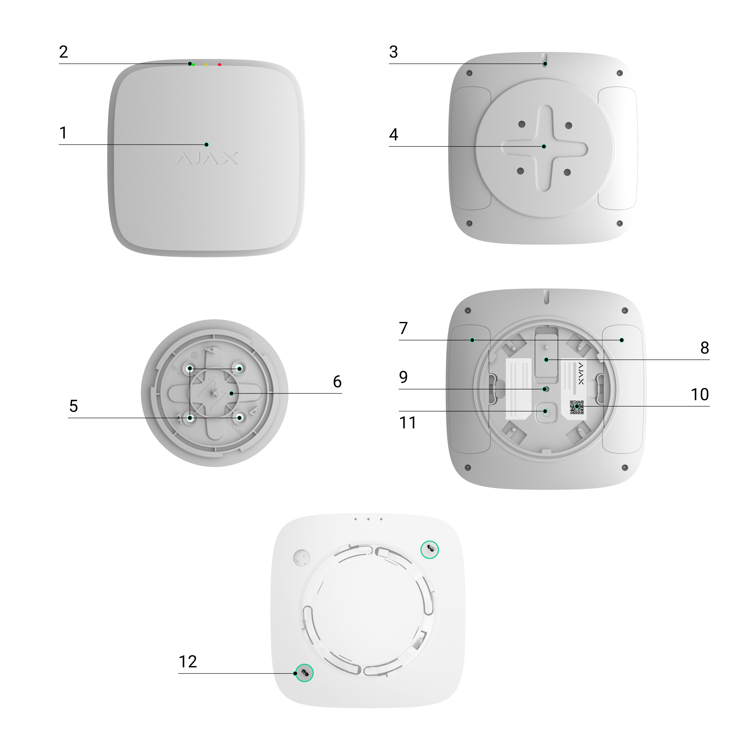
- Front panel of the detector.
- LED indicators: green, yellow, and red.
- Hole for a special tool used to unlock the lock.
- SmartBracket mounting panel. To remove the panel, insert the special tool into the corresponding hole and turn SmartBracket counterclockwise. If the device is unlocked, simply turn SmartBracket counterclockwise.
- Fixing points to attach SmartBracket to the surface.
- ↑↑ sign on SmartBracket. You can use it as a reference point to align the device properly when attaching the mounting panel to the surface.
- Battery compartment lids. To replace the batteries, open the lids.
- Lock to secure the device on SmartBracket (optionally).
- Tamper button. It triggers in case of an attempt to remove the device from the mounting panel.
- QR code with the device ID. It is used to add the device to the CIE.
- Power button.
- Thermistors that detect dangerous temperatures.
Compatible CIEs and range extenders
The device requires the Ajax CIE with an up-to-date OS Malevich version.
Operating principle
EN54 FireProtect (Heat) Jeweller is a wireless fire detector with a heat sensor, which is designed for indoor installation. The detector is always active and responds to a fire 24/7, regardless of the system’s security mode.
The device is powered by pre-installed batteries and does not require an external power supply. EN54 FireProtect (Heat) Jeweller monitors its operational state and informs the system of faults if any occur.
EN54 FireProtect (Heat) Jeweller is equipped with a tamper button that triggers if someone attempts to remove the device from the mounting panel.
Heat sensor
Two built-in thermistors detect a rapid temperature rise or when the temperature exceeds the threshold value. The thermistors trigger an alarm when a rapid temperature rise or static temperature is detected. The threshold temperature, temperature rise rate, and the response time at which the detector raises an alarm depend on the detector settings and comply with the requirements of the EN 54-5 standard.
Available heat sensor modes:
- A1, A1R, A1S.
- B, BR, BS.
- C, CR, CS.
- Fixed temperature.
Only the following heat sensor modes are compliant with EN 54 requirements: A1R, A1S, BR, BS, CR, and CS.
Jeweller data transfer protocols
Jeweller is a wireless data transfer protocol that provides fast and reliable two-way communication between the CIE and devices. The device uses Jeweller to transmit commands, alarms, and events.
Sending events to the monitoring station
An Ajax system can transmit alarms to both the Ajax PRO Desktop app and the monitoring station in the formats of SurGard (Contact ID), SIA (DC-09), ADEMCO 685, and other protocols.
A system with EN54 FireProtect (Heat) Jeweller installed can transmit the following events:
- Fire alarm / recovery after the alarm.
- Heat sensor hardware fault/recovery.
- Battery charge is low/OK.
- Tamper alarm/recovery.
- Loss/recovery of communication between EN54 FireProtect (Heat) Jeweller and the CIE.
The system allows disabling fault indication and notifications of Jeweller connection loss for EN54 devices used in mobile environments, such as fire engines.
How to disable Jeweller connection loss notifications for EN54 devices
When an alarm is received, the operator at the monitoring station knows precisely what happened and where. The addressability of Ajax devices allows sending events to Ajax PRO Desktop or the monitoring software, including the device type, its name, fire zone, virtual room, and location description. Please note that the list of transmitted parameters may vary depending on the monitoring software and the selected communication protocol for the monitoring station.
You can find the device ID and zone number in the device states.
Selecting the installation site
The detector is designed for indoor installation only.
Follow your local fire safety regulations when selecting the device installation site.
When choosing where to place the detector, consider the parameters that affect its operation:
- Jeweller signal strength.
- Distance between the device and the CIE.
- Presence of obstacles to radio signal transmission.
Consider the placement recommendations when developing a system project. Only specialists may design and install Ajax systems. A list of recommended partners is available here.
Signal strength
The signal strength is determined by the number of undelivered or corrupted data packets over a certain period of time. The icon ![]() in the Devices
in the Devices ![]() tab in Ajax apps indicates the signal strength:
tab in Ajax apps indicates the signal strength:
- three bars — excellent signal strength;
- two bars — good signal strength;
- one bar — low signal strength, stable operation is not guaranteed;
- crossed-out icon — no signal.
Note that if the signal strength is excellent, the device can automatically adjust the radio transmission power to reduce power consumption and radio interference.
Run the Jeweller signal strength test before final installation. The test checks the signal strength at the device’s maximum transmission power. To comply with EN 54 requirements, the signal strength between the device and the CIE must be at least two bars.
If the test shows the signal strength of one or zero bars, we do not guarantee the device will operate stably. Consider relocating the detector, as adjusting its position even by 8 inches or rotating it relative to the CIE can significantly improve the signal strength. If the signal remains poor or unstable after relocation, consider using an Ajax radio signal range extender.
Refer to the functionality testing section to learn how to run the Jeweller signal strength test.
Where not to install the device
- Outdoors. This can lead to detector failure.
- Indoors, where the temperature and humidity are outside the permissible limits. This may damage the detector.
- In places with fast air circulation. For example, near fans, vents, open windows, or doors. This may interfere with fire detection.
- Opposite any objects whose temperature changes rapidly, such as electric and gas heaters. This may cause false alarms.
- In the corners of the room. This may interfere with fire detection.
- In bathrooms, showers, or other areas where the temperature changes rapidly. This may cause false alarms.
- Near lighting fixtures, decorations, and other interior items that may interfere with the circulation of air on the premises. This may interfere with fire detection.
- On surfaces that are usually warmer or colder than the rest of the premises. For example, on skylights. Temperature fluctuations may interfere with fire detection.
- In places with low or unstable Jeweller signal strength. This may result in losing connection to the CIE.
- Closer than 3 ft to the CIE or radio signal range extender.
Installation
Before installing EN54 FireProtect (Heat) Jeweller, ensure that you have selected the optimal location that complies with the requirements of this manual.
Only a professional must install this device.
To install the device:
- Remove the SmartBracket mounting panel from the device. To remove the panel, turn it counterclockwise.

Use the device only with FP.54H.J-000-EU, FP.54HA.J-000-EU, FP.54S.J-000-EU, or FP.54SA.J-000-EU SmartBracket mounting panels.
- Secure the SmartBracket panel to a surface using double-sided adhesive tape or other temporary fasteners. The ↑↑ sign on SmartBracket is for informational purposes only. It can help you align the device properly.
Use double-sided adhesive tape for temporary fixation only. The device secured by the adhesive tape can detach from the surface at any time, which may result in damage if it falls.
- Add EN54 FireProtect (Heat) Jeweller to the CIE.
- Place the device on the SmartBracket mounting panel.
- Run the device functionality testing.
- Remove the device from the mounting panel.
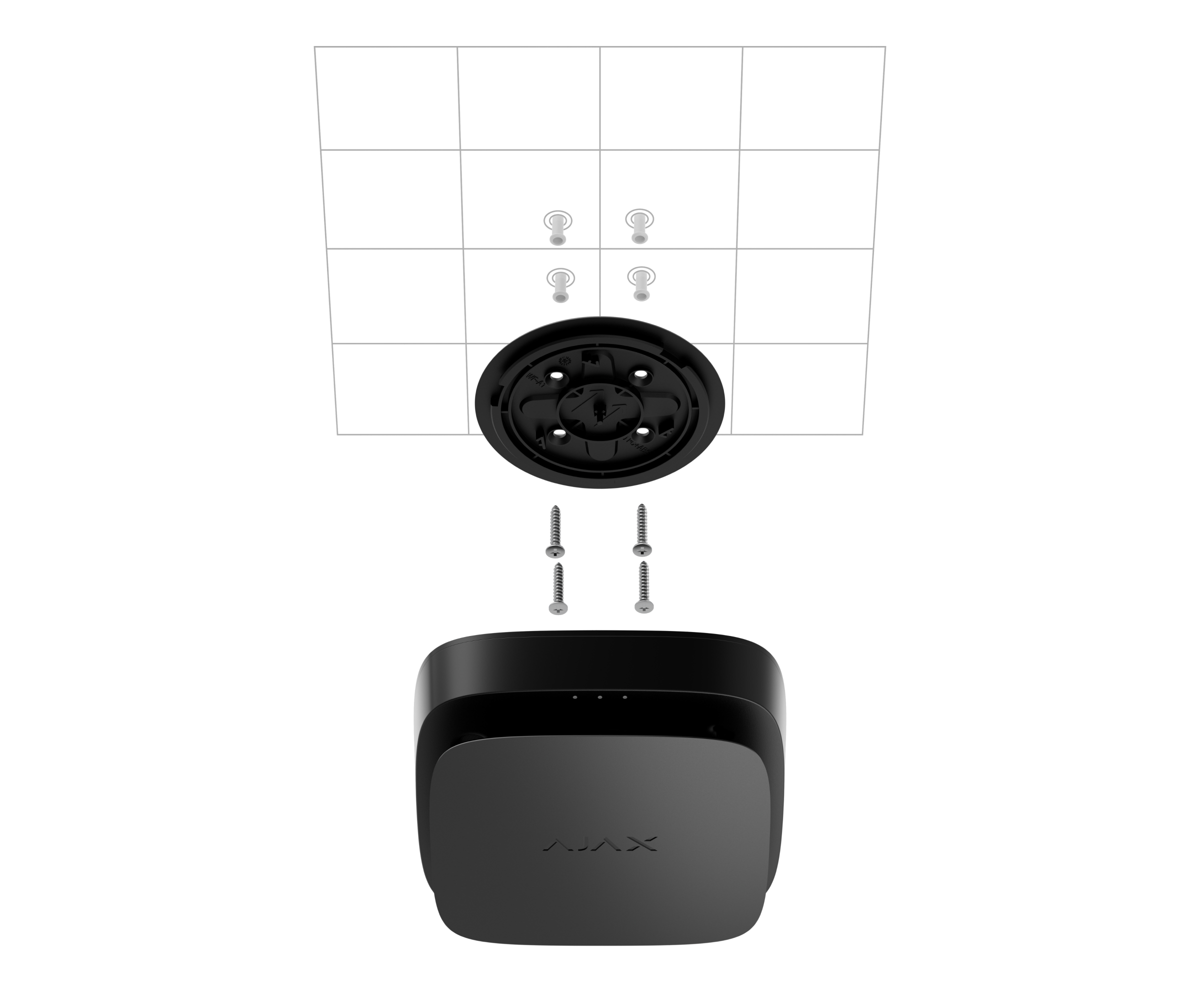
- Attach the SmartBracket panel to the surface using the bundled screws for all fixing points. When using other fasteners, ensure they do not damage or deform the mounting panel.
- To additionally secure the device on SmartBracket with the lock, move the locking mechanism to
 position. In this case, you will need to insert a special tool into the corresponding hole to remove the mounting panel.

- Place the device on the SmartBracket mounting panel.
- Adjust the device position if necessary. The SmartBracket mounting panel allows the detector to be rotated up to 90°.
Adding to the system
The CIE and the device must operate at the same radio frequency; otherwise, they are incompatible. The radio frequency range of the device may vary based on the region. We recommend purchasing and using Ajax devices in the same region. You can verify the range of operating radio frequencies with the technical support service.
Before adding the module
- Install an Ajax app.
- Log in to your account or create a new one.
- Select a space or create a new one.
- Add at least one virtual room.
- Add a compatible CIE to the space. Ensure the CIE is switched on and has internet access via Ethernet, Wi-Fi, and/or mobile network.
- Check the states in the Ajax app to ensure the space is disarmed and the CIE is not starting an update.
Only a PRO or a space admin with the rights to configure the system can add the device to the CIE.
Adding to the CIE
- Open an Ajax app. Select a space to which you want to add the device.
- Go to the Devices
 tab and tap Add device.
 - Scan the QR code or enter the device ID manually. A QR code with the ID is placed on the device under the SmartBracket mounting panel. Also, it is duplicated on the device packaging.

- Assign a name to the device.
- Select a fire zone and a virtual room.
- If necessary, specify the device location in the Location field.
- Select Add device, and the countdown will begin.
- Switch on the device by holding the power button for 3 seconds.

Once added to the CIE, the device will appear in the list of CIE devices in the Ajax app. The update frequency for device states in the list depends on the Jeweller settings and is 36 seconds by default.
If the connection fails, try again in 5 seconds. If the maximum number of devices has already been added to the CIE, you will receive an error notification when you try to add more.
EN54 FireProtect (Heat) Jeweller works with only one CIE. When added to a new CIE, the device stops sending events to the old one. After the device is added to a new CIE, it will not be automatically removed from the device list of the old CIE. This must be done through the Ajax app.
Functionality testing
An Ajax system provides the Jeweller signal strength test to help select the correct installation place for the devices. The test allows you to determine the signal strength and stability between the CIE (or the radio signal range extender) and the device via the wireless Jeweller data transfer protocol at the device installation site.
To run the test:
Icons
Icons in an Ajax app display some of the EN54 FireProtect (Heat) Jeweller states. You can check the icons in the Devices ![]() tab.
tab.
| Icon | Meaning |
|
Jeweller signal strength. It displays the signal strength between the CIE or the range extender and the device. The recommended value is 3 bars. |
|
|
Battery charge level of the device. |
|
|
The device operates via the radio signal range extender. |
|
| The detector has detected a rapid temperature rise. | |
| The detector has detected that the temperature threshold has been exceeded. | |
| EN54 FireProtect (Heat) Jeweller has a fault. The list of faults is available in the device states. | |
| EN54 FireProtect (Heat) Jeweller is disabled. | |
| The device has lost connection with the CIE, or the CIE has lost connection with the Ajax Cloud server. | |
|
The device has not been transferred to the new CIE. |
States
The states include information about the device and its operating parameters. You can find the states of EN54 FireProtect (Heat) Jeweller in Ajax apps:
- Go to the Devices tab.
- Select EN54 FireProtect (Heat) Jeweller from the list.
| Parameter | Meaning |
| Alarm |
The device has detected a fire. Tapping on The field is displayed only if a fire is detected. |
| Data import | Displays the error when the data is being transferred to the new CIE:
|
| Fault |
The device has a fault. Tapping on The field is displayed only if a fault is detected. |
| Disabled |
The device or some of its functions are disabled. It does not respond to the alarm or notify users and the monitoring station. Tapping on The field is displayed only if the device is disabled. |
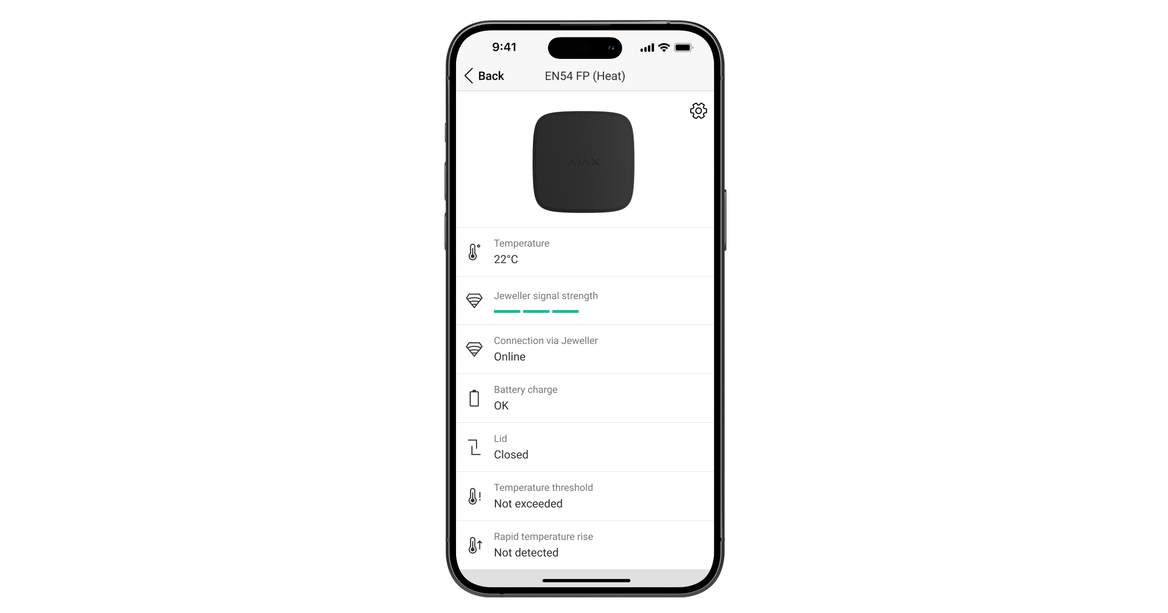
| Temperature |
Air temperature on the premises where the device is installed. Measured in degrees Celsius or Fahrenheit, depending on the app settings. In the normal state, the temperature value is displayed in black. When the temperature rises, the field is highlighted in red. |
| Jeweller signal strength |
Jeweller signal strength between the device and the CIE (or the radio signal range extender). The recommended value is 3 bars. Jeweller is a protocol for transmitting commands, events, and alarms. |
| Connection via Jeweller | The connection state via the Jeweller channel between the device and the CIE (or the range extender):
|
<Range extender name> |
The connection state between the device and the radio signal range extender.
The field is displayed if the device operates via the radio signal range extender. |
| Battery charge | The device’s battery charge level. Three states are available:
When the batteries need to be replaced, users and the monitoring company will receive appropriate notifications. |
| Lid | The state of the device’s tamper button that responds to the detachment or opening of the device enclosure:
|
| Temperature threshold | Alarm state if a temperature threshold is exceeded:
If a temperature threshold exceedance is detected, the text field is highlighted in red. |
| Rapid temperature rise | Alarm in case of a rapid temperature rise:
If a rapid temperature rise is detected, the text field is highlighted in red. |
| Fire zone | The number and name of the fire zone to which the device is assigned. |
| Room | The name of the room to which the device is assigned. |
| Location | The detailed device location description. |
| Firmware | Device firmware version. |
| Device ID | The EN54 FireProtect (Heat) Jeweller ID. It is also available on the QR code on the device enclosure and on its packaging. |
| Device No. | Number of the device loop (zone). |
Settings
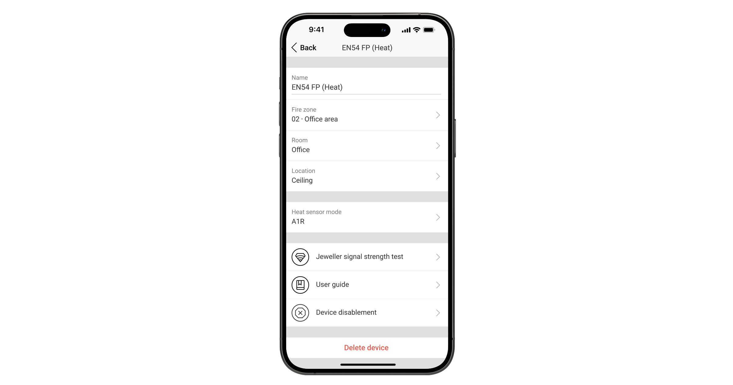
To change EN54 FireProtect (Heat) Jeweller settings, in an Ajax app:
- Go to the Devices tab.
- Select EN54 FireProtect (Heat) Jeweller from the list.
- Go to Settings
 .
. - Set the required settings.
- Tap Back to save the new settings.
| Settings | Meaning |
| Name |
Name of the device. It is displayed in the list of CIE devices, SMS text, and notifications in the event feed. To change the device name, tap on the text field. The name can contain up to 24 Latin characters or up to 12 Cyrillic characters. |
| Fire zone |
Selecting the fire zone to which EN54 FireProtect (Heat) Jeweller is assigned. The fire zone is displayed in the text of SMS and notifications in the event feed. |
| Room |
Selecting the virtual room to which EN54 FireProtect (Heat) Jeweller is assigned. The room name is displayed in the text of SMS and notifications in the event feed. |
| Location |
The detailed location of the device. It is displayed next to the room in the event feed notifications. The location text can contain up to 24 Latin or Cyrillic characters. |
| Heat sensor mode | Selecting the heat sensor mode depending on the installation site:
If the EN 54 compliance mode is enabled for the system, the A1, B, C, and Fixed temperature heat sensor modes are not available. |
| Jeweller signal strength test |
Switching the device to the Jeweller signal strength test mode. The test allows you to check the signal strength between the CIE (or the radio signal range extender) and the device via the wireless Jeweller data transfer protocol to select the optimal installation site. |
| User guide | Opening the EN54 FireProtect (Heat) Jeweller user manual in an Ajax app. |
| Device disablement |
The option allows for deactivating the device. The device remains within the system but will no longer detect signs of fire or raise an alarm. |
| Delete device | Unpairing the device, disconnecting it from the CIE, and deleting its settings. |
Indication
EN54 FireProtect (Heat) Jeweller LED indicators inform about alarms, faults, and other device states.
| Event | LED indication | Note |
| Alarm. | The red LED lights up for 1 second, then goes off for 1 second constantly. |
The device stops alarming as soon as the fire alarm is reset. Also, you can mute the alarm by tapping the Silence alarm button on the CIE touch screen or in an Ajax app. |
| Turning on the device. | The green, yellow, and red LEDs light up in turn and then go off. | Press the power button until the green LED lights up. |
| Turning off the device. | The green, yellow, and red LEDs light up simultaneously and then go off in reverse order. | Press the power button until the red LED goes off. |
| Adding to the CIE is in progress. | The green LED is permanently on. | The indication turns off after the detector is added to the CIE. |
| The device has been removed from the CIE. | The green LED flashes 6 times in a row. | The indication turns on when the detector receives information that it has been removed from the CIE. |
| The battery is completely discharged. | The yellow LED constantly flashes. | The battery needs to be replaced. |
| Turning off the device when the battery is completely discharged. | The green, yellow, and red LEDs light up simultaneously and then go off in reverse order. | The battery needs to be replaced. |
|
Tamper alarm. The device has been removed from the SmartBracket mounting panel. |
The yellow LED lights up for 1 second. | |
| The device is installed on the SmartBracket mounting panel. | The green LED lights up for 1 second. | |
| Performing the Jeweller signal strength test. | The indication depends on the signal strength:
|
Faults
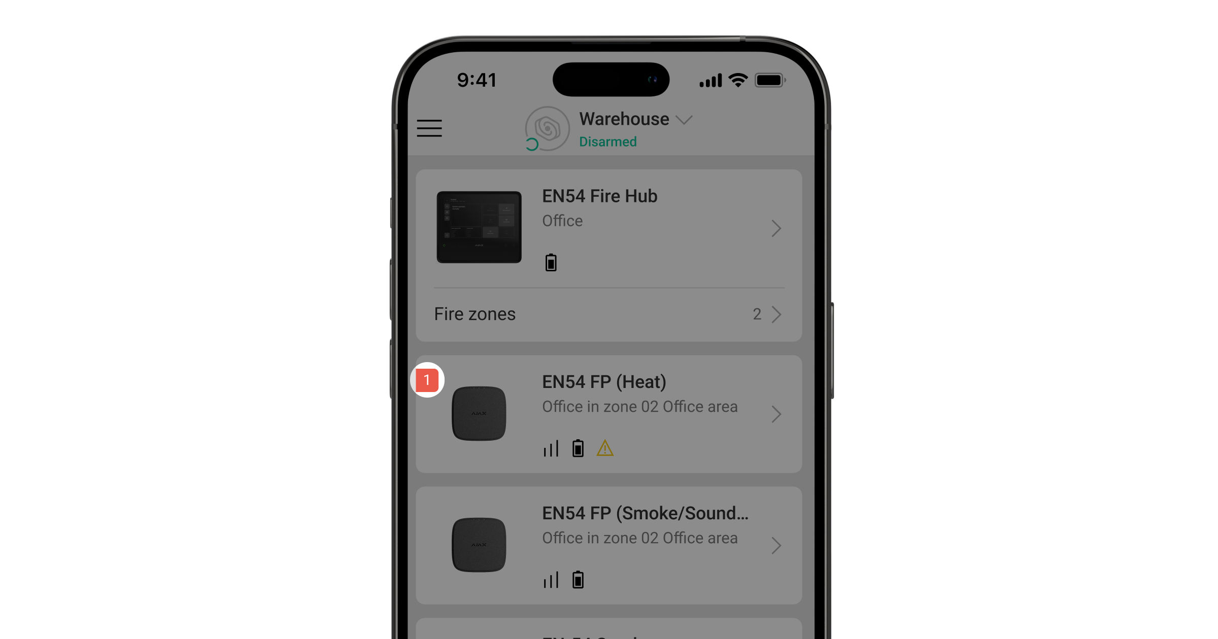
When an EN54 FireProtect (Heat) Jeweller fault is detected, an Ajax app displays a fault counter on the device icon. All faults are indicated in the device states. Fields with faults are highlighted in yellow. Also, faults are displayed in the Control tab of the CIE display. More details about the fault can be found in the Event center or Fire zones tabs of the CIE.
A fault of the EN54 FireProtect (Heat) Jeweller is displayed if:
- The device is removed from the SmartBracket mounting panel, or its integrity is compromised (the tamper button has been triggered).
- There is no connection with the CIE or radio signal range extender via Jeweller.
- The device battery is low.
- The device has a hardware fault (failure of one or more device components).
An admin or a user with access level 2 can disable the notifications of Jeweller connection loss. The Deactivate notifications feature allows disabling fault indication and notifications of Jeweller connection loss for EN54 devices used in mobile environments, such as fire engines.
Maintenance
Regularly check the device operation. Clean the device enclosure from dust, cobwebs, and other contaminants as they emerge. Use soft, dry wipes suitable for equipment maintenance. Do not use substances that contain alcohol, acetone, gasoline, and other active solvents to clean the device.
The pre-installed batteries provide up to 6 years of autonomous operation with the standard Jeweller settings (the polling interval is 36 seconds). If the batteries are low, the system will send an appropriate notification.
We recommend replacing the batteries immediately upon receiving the notification. It is advisable to use Huiderui CR123A, 3 V, 1,600 mAh, LiMnO2 batteries.
Ensure the batteries are installed with the correct polarity. The polarity is marked inside the enclosure. After replacing the batteries, run the functionality test to ensure the device operates properly.
Warranty
Warranty for the Limited Liability Company “Ajax Systems Manufacturing” products is valid for 2 years after the purchase.
If the device does not operate properly, we recommend contacting Ajax Technical Support first. In most cases, technical issues can be resolved remotely.
Contact Technical Support:
Manufactured by “AS Manufacturing” LLC
