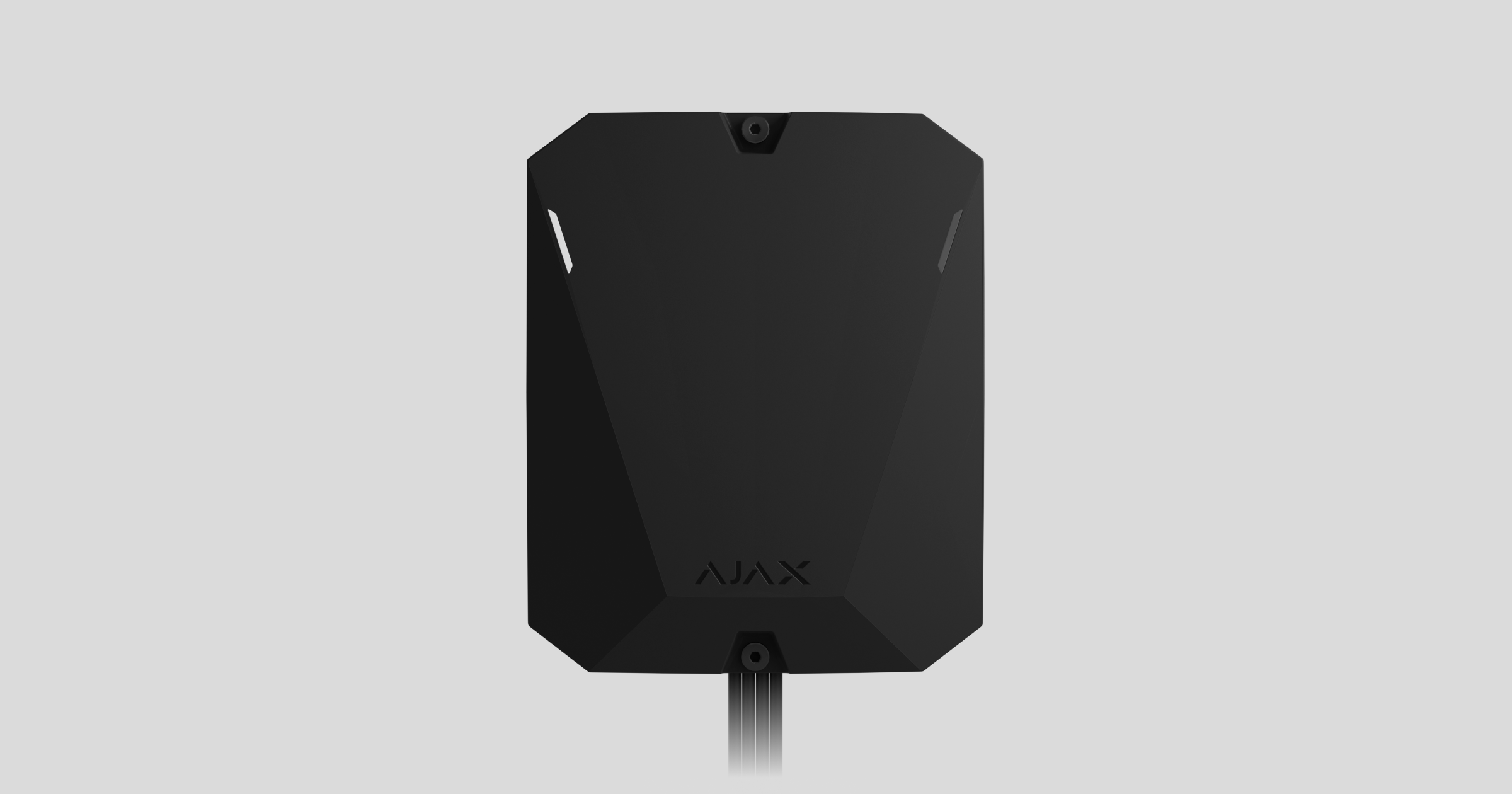
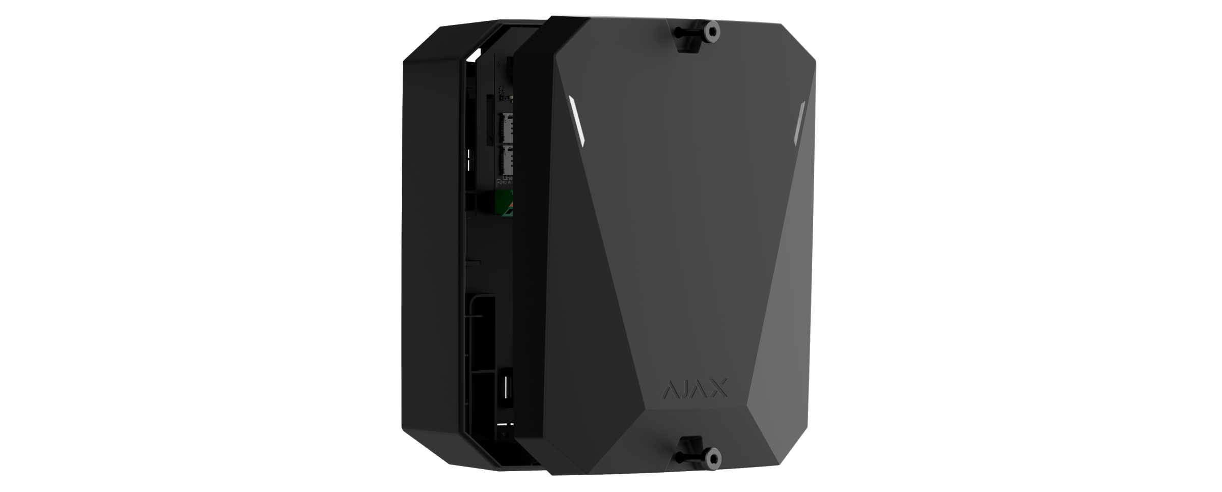
Superior Hub Hybrid é um painel de controlo híbrido do sistema de segurança Ajax. Compatível com dispositivos Ajax com e sem fios. Controla o funcionamento dos dispositivos ligados, interage com o utilizador e a empresa de segurança. Destinado à instalação no interior.
O Superior Hub Hybrid precisa de acesso à Internet para se ligar ao serviço de Ajax Cloud. Canais de comunicação disponíveis: Ethernet e dois cartões SIM. O hub está disponível em quatro versões:
- na carcaça de origem com modem 2G — Superior Hub Hybrid (2G),
- na carcaça de origem com modem 2G/3G/4G (LTE) — Superior Hub Hybrid (4G) revisão 1 (data de fabrico anterior a junho de 2025),
- na carcaça padrão com modem de 2G/3G/4G (LTE) — Superior Hub Hybrid (4G) revisão 2 (data de fabrico a partir de junho de 2025),
- como uma placa sem carcaça com modem 2G/3G/4G (LTE) — Superior Hub Hybrid (4G) (without casing).
Este é um dispositivo da linha de produtos Superior. Apenas os parceiros acreditados da Ajax Systems podem vender, instalar e administrar os produtos Superior.
Elementos funcionais
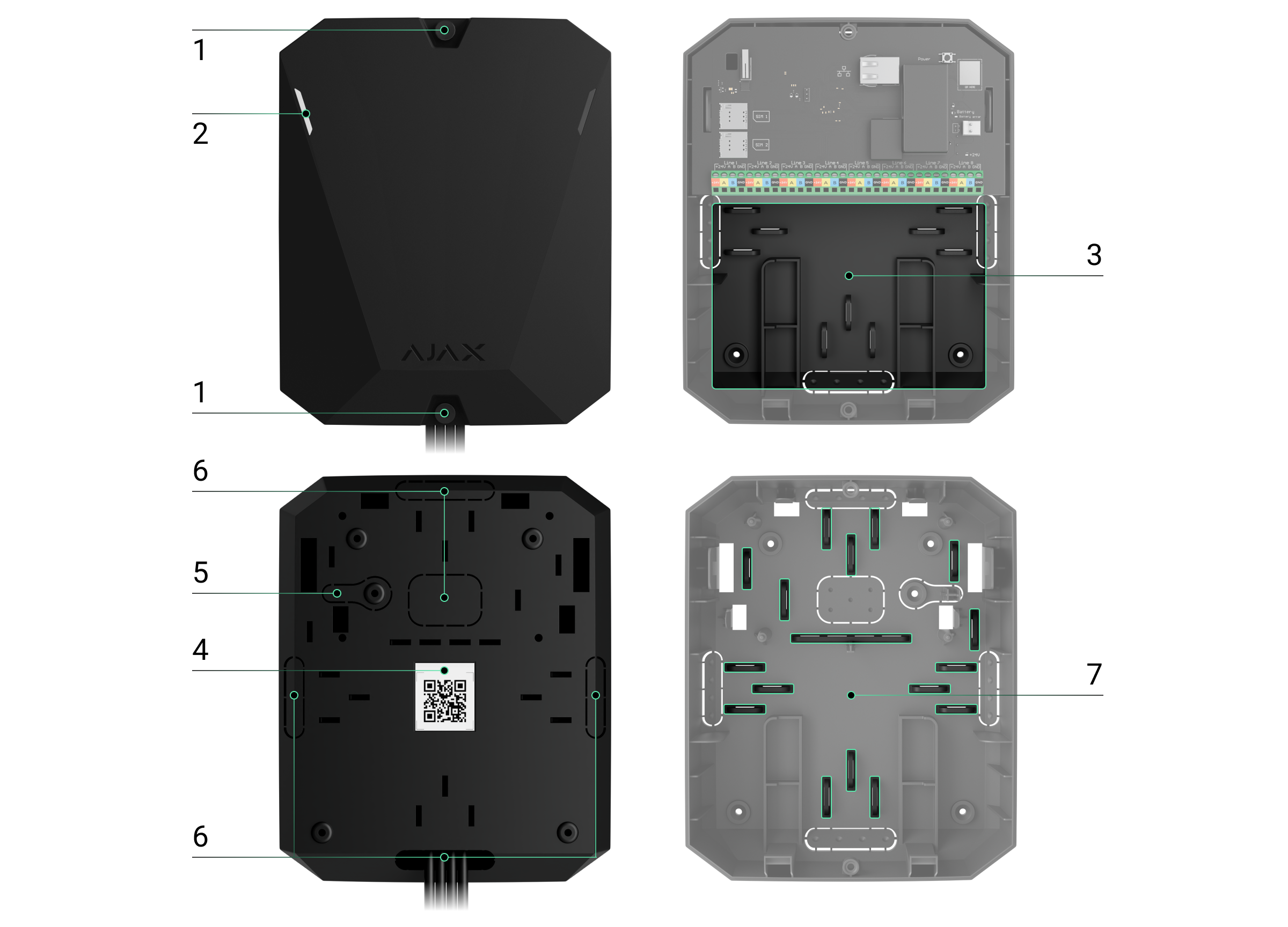
Elementos da carcaça
- Parafusos que fixam a tampa da carcaça. Desaparafusar com uma chave hexagonal (Ø 4 mm).
- Guias luminosas para a indicação do estado do hub (disponível na nova versão da carcaça; na versão anterior, o indicador LED está localizado na placa).
- Uma peça com suportes para uma bateria de reserva.
Bateria não incluída.
- Código QR e ID (número de série) do painel de controlo.
- Parte perfurada da carcaça. Necessário para o acionamento de tamper em caso de qualquer tentativa de desprender o dispositivo da superfície. Não o parta.
- Partes perfuradas da carcaça para a saída dos fios dos detetores e dispositivos ligados.
- Fixadores de cabos.
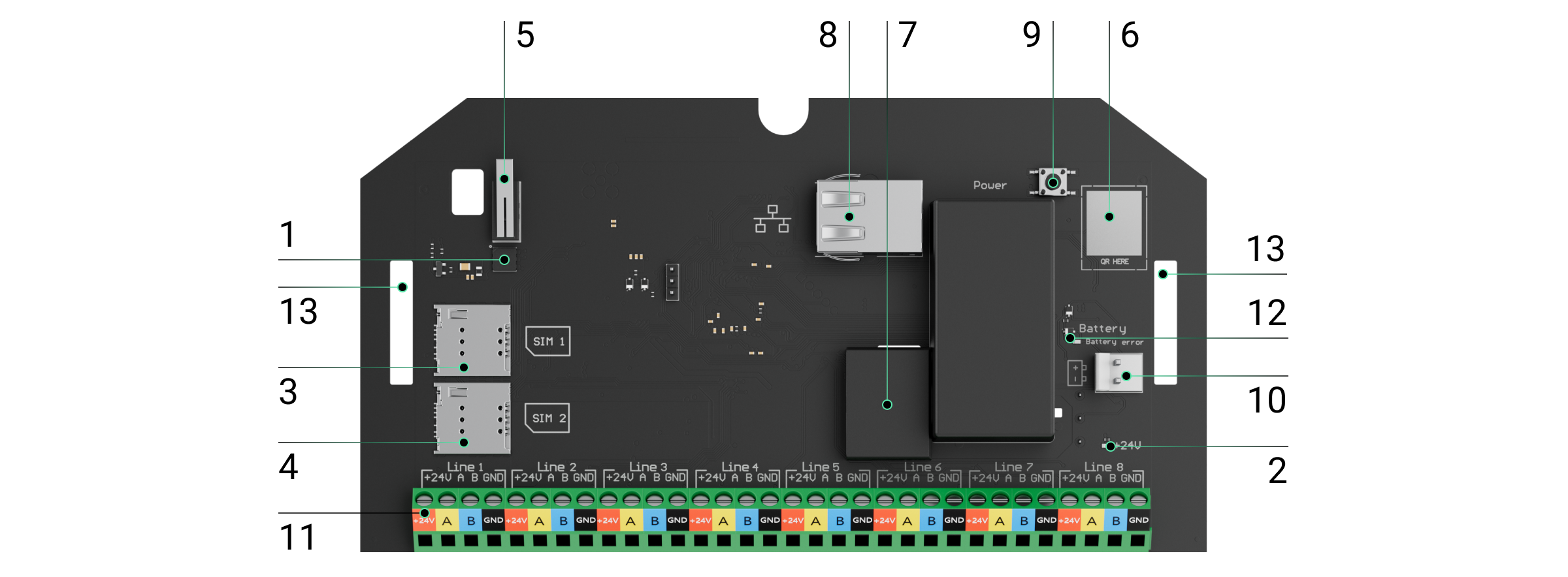
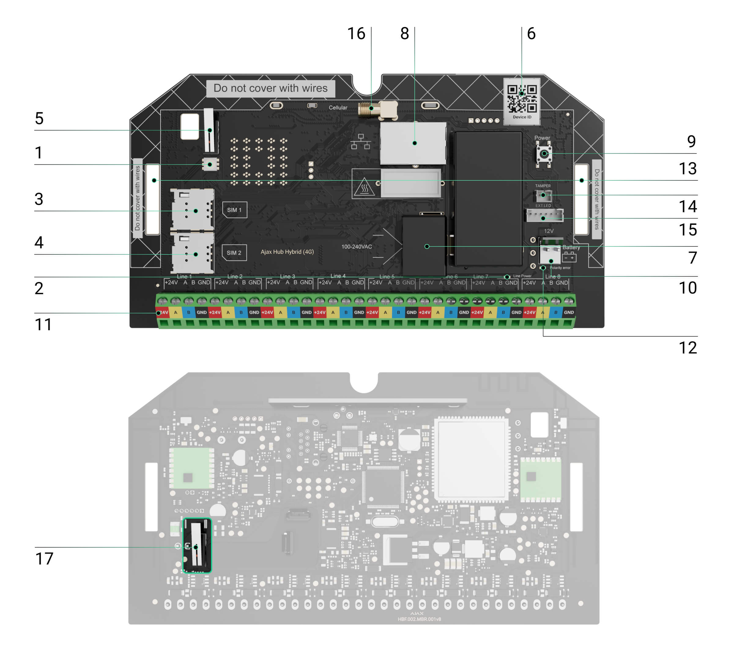
Elementos da placa
- Indicador de estado LED do hub e dos canais de comunicação conectados.
- Indicador de estado LED dos dispositivos conectados às linhas de Fibra do hub.
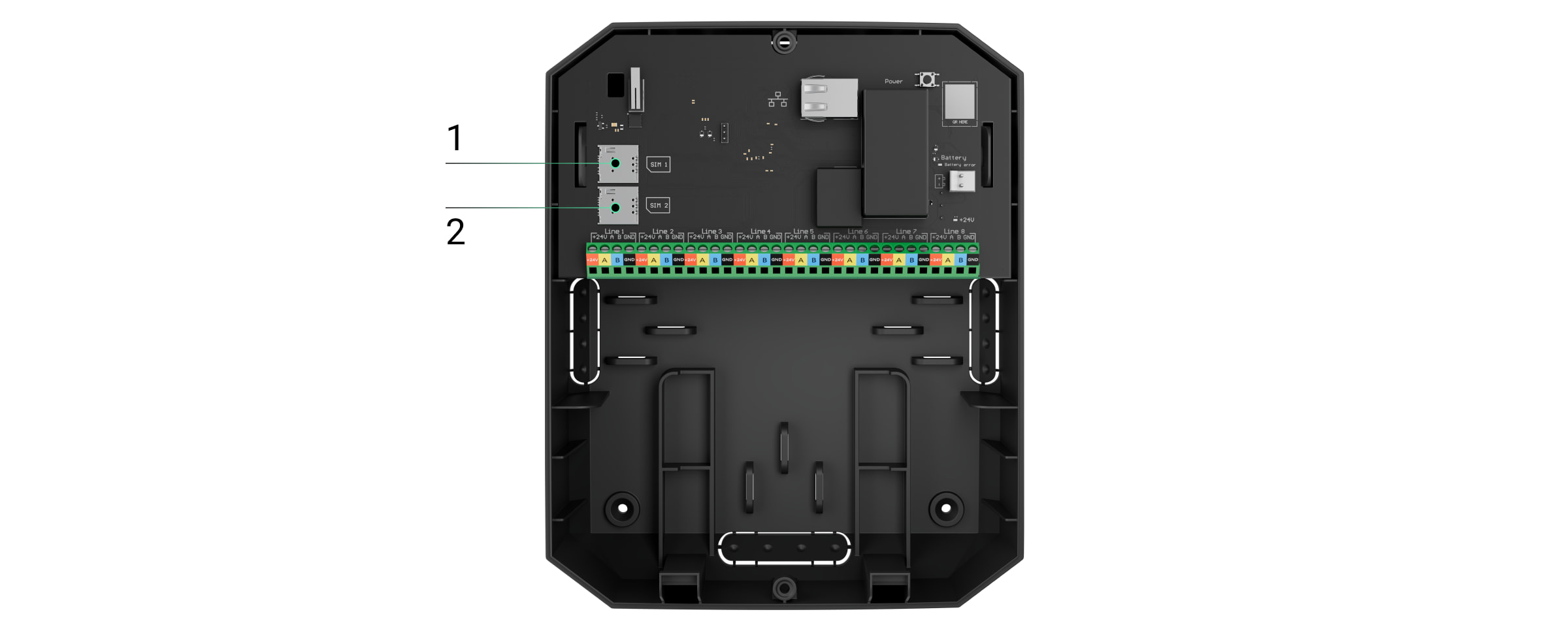
- Ranhura para micro SIM 1.
- Ranhura para micro SIM 2.
- Botão de tamper. Deteta quando a tampa da carcaça do Superior Hub Hybrid (2G) é retirada.
- Código QR e ID (número de série) do dispositivo.
- Conector do cabo de alimentação.
- Conector do cabo Ethernet.
- Botão de alimentação.
- Terminais para ligação de uma bateria de reserva de 12 V.
- Terminais de linhas Fibra para ligação de dispositivos com fios.
- Indicador de Erro da bateria. Acende-se em caso de inversão de polaridade ao ligar a bateria (quando a bateria “-” é ligada ao terminal “+” e vice-versa).
- Furos de montagem para fixar a placa Superior Hub Hybrid (2G) à carcaça do hub.
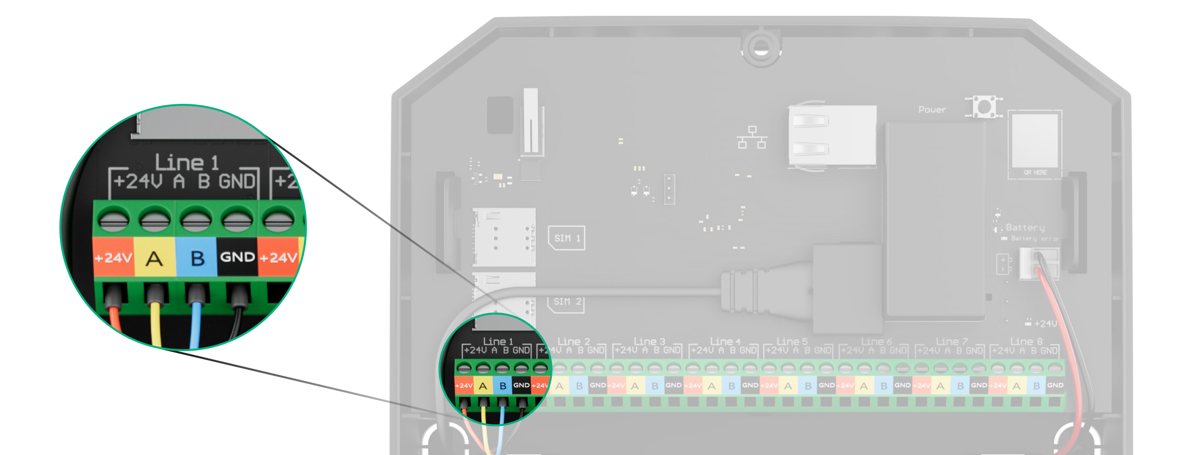
Terminal de linha Fibra
Superior Hub Hybrid com 8 linhas Fibra. Os números de 1 a 8 estão indicados no quadro do painel de controlo.
Terminal de linha Fibra:
- +24 V — terminal de alimentação elétrica de 24 V⎓.
- A — primeiro terminal de sinal.
- B — segundo terminal de sinal.
- GND — terminal de ligação à terra.
Respeite a polaridade e a ordem de ligação dos fios aquando da instalação dos dispositivos Fibra.
Princípio do funcionamento
O Superior Hub Hybrid é um painel de controlo híbrido do sistema de segurança Ajax. Controla o funcionamento dos dispositivos ligados.
Pode ligar até 100 dispositivos Ajax com e sem fios ao Superior Hub Hybrid. Os dispositivos ligados protegem contra intrusões, incêndios e inundações e também permitem controlar aparelhos elétricos de acordo com cenários ou manualmente — numa app móvel ou premindo o botão de pânico, o LightSwitch ou o teclado com ecrã tátil.
Para monitorizar o funcionamento de todos os dispositivos do sistema de segurança, o hub comunica com os dispositivos ligados através de três protocolos encriptados:
1. Jeweller é um protocolo de rádio para a transmissão de eventos e alarmes a partir de dispositivos sem fios Ajax. O alcance da comunicação é de até 2000 m sem obstáculos: paredes, portas ou construções entre pisos.
2. Wings é um protocolo de rádio para a transmissão de fotografias dos detetores MotionCam e MotionCam Outdoor. O alcance da comunicação é de 1700 m sem obstáculos (paredes, portas ou construções entre pisos.
3. Fibra é um protocolo com fio para transmitir eventos e alarmes de dispositivos com fio Ajax. O alcance da comunicação é de até 2000 m quando conectado através de um cabo de par entrançado U/UTP cat.5.
Se um detetor for acionado, o sistema dispara um alarme em menos de um segundo, independentemente do protocolo de comunicação. Em caso de alarme, o hub ativa as sirenes, inicia os cenários e notifica a central de vigilância da empresa de segurança e todos os utilizadores.
Proteção contra sabotagem
O Superior Hub Hybrid tem 3 canais de comunicação para ligação ao servidor Ajax Cloud: Ethernet e dois cartões SIM. Isto permite-lhe ligar o dispositivo a três fornecedores de comunicações diferentes ao mesmo tempo. Se um dos canais de comunicação estiver indisponível, o hub muda automaticamente para outro e informa a estação de controlo da empresa de segurança e os utilizadores do sistema.
Quando é detetada uma tentativa de inibição, o sistema muda para uma frequência de rádio inativa e envia notificações para a estação de controlo da empresa de segurança e para os utilizadores do sistema.
O hub verifica regularmente a qualidade da comunicação com todos os dispositivos ligados. Se algum dispositivo perder a ligação com o painel de controlo, após o tempo especificado pelo administrador, todos os utilizadores do sistema (dependendo das definições), bem como a estação de monitorização da empresa de segurança, receberão uma notificação sobre o incidente.
Ninguém pode desligar o hub sem ser detetado, mesmo quando a instalação está desarmada. Se um intruso tentar abrir a carcaça do hub, o botão de tamper é imediatamente acionado. A notificação de alarme será enviada à empresa de segurança e aos utilizadores do sistema.
O hub verifica a ligação do Ajax Cloud em intervalos regulares. O período de ping é especificado nas definições do hub. Se for definido um período mínimo de ping, o servidor pode notificar os utilizadores e a empresa de segurança em apenas 60 segundos após a perda da ligação.
A bateria de reserva de 7 A∙h pode ser ligada ao hub, o que pode fornecer um sistema de 30 detetores com energia de reserva durante 60 horas.
Utilize baterias de 12 V⎓ com uma capacidade de 4, 7 ou 9 A∙h. Existem suportes especiais para as baterias na carcaça do painel de controlo.
Pode utilizar baterias de capacidade diferente, adequadas ao tamanho do hub e com um tempo de carga total não superior a 40 horas. A corrente máxima de carregamento da bateria a partir do Superior Hub Hybrid é de 300 mA. As dimensões máximas da bateria a instalar na carcaça do Superior Hub Hybrid são 151 × 65 × 94 mm e o peso é de 5 kg.
OS Malevich
O Superior Hub Hybrid é gerido pelo sistema operativo em tempo real OS Malevich. Está protegido contra vírus e ciberataques.
O OS Malevich traz novas características e funcionalidades para o sistema de segurança Ajax através de atualização por via aérea. A atualização não requer a intervenção de um técnico de instalação ou de um utilizador.
A atualização demora até 2 minutos com o sistema de segurança desarmado e a fonte de alimentação externa e a bateria de reserva ligadas.
Indicação
O Hub tem dois modos de indicação LED:
- Ligação hub — servidor.
- Alertas e Avarias.
Ligação Hub — servidor
O modo Ligação Hub — servidor está ativado por predefinição. O LED do hub tem uma lista de indicações que mostram o estado do sistema ou os eventos que estão a ocorrer. O Superior Hub Hybrid pode acender-se a vermelho, branco, roxo, amarelo, azul ou verde, consoante o estado.
Na versão anterior da carcaça do Superior Hub Hybrid, o indicador LED não é visível quando a tampa da carcaça está fechada. O indicador só é útil durante a ligação e a configuração do hub. Na nova versão, a carcaça do Superior Hub Hybrid apresenta guias de luz, permitindo a visualização do estado do hub em qualquer altura.
Os estados do Superior Hub Hybrid também podem ser monitorizados nas apps Ajax.
| Indicação | Evento | Nota |
| Ilumina-se a branco. | Estão ligados pelo menos dois canais de comunicação: Ethernet e um ou dois cartões SIM. | Quando estiver a funcionar apenas com uma bateria de reserva, o indicador piscará a cada 10 segundos. |
| Ilumina-se a verde. |
Está ligado um canal de comunicação: Ethernet ou um/dois cartões SIM. |
Quando estiver a funcionar apenas com uma bateria de reserva, o indicador piscará a cada 10 segundos. |
| Ilumina-se a vermelho. | O hub não tem ligação à Internet ou ao serviço Ajax Cloud. | Quando estiver a funcionar apenas com uma bateria de reserva, o indicador piscará a cada 10 segundos. |
|
A fonte de alimentação externa está desligada (se houver uma bateria de reserva conectada). |
Acende-se continuamente por 3 minutos, depois piscas a cada 10 segundos. | A cor da indicação depende do número de canais de comunicação ligados. |
Se, durante a utilização do sistema, surgir uma indicação que não conste do presente manual do utilizador, contacte o serviço de apoio Ajax
Acesso às indicações
Os utilizadores do Superior Hub Hybrid podem ver a indicação Alertas e avarias depois de:
- Armar/desarmar o sistema utilizando o teclado Ajax.
- Introduzir o ID de utilizador ou código pessoal correto no teclado e executar uma ação que já tenha sido executada (por exemplo, o sistema está desarmado e o botão de desarmar é premido no teclado).
- Premir o botão Ajax SpaceControl Jeweller para armar/desarmar o sistema ou ativar o Modo Noturno.
- Armar/desarmar o sistema utilizando apps Ajax.
Todos os utilizadores podem ver a indicação do Mudar o estado do hub.
Alertas e Avarias
A função é ativada nas definições do hub na app PRO (Hub → Definições → Serviços → Indicação LED).
A indicação está disponível para hubs com o firmware OS Malevich 2.14 e superior e em aplicações destas versões e superiores:
- Ajax PRO: Tool for Engineers 2.22.2 para iOS.
- Ajax PRO: Tool for Engineers 2.25.2 para Android.
- Ajax PRO Desktop 3.5.2 para macOS.
- Ajax PRO Desktop 3.5.2 para Windows.
| Indicação | Evento | Nota |
| Alterar o estado do hub | ||
| O LED branco pisca uma vez por segundo. | Armar em Duas Fases ou Atraso ao Sair. | Um dos dispositivos está a executar a função de Armar em Duas Fases ou Atraso ao Sair. |
| O LED verde pisca uma vez por segundo. | Indicação de entrada. | Um dos dispositivos está a executar o Atraso ao Entrar. |
| O LED branco acende-se durante 2 segundos. | O armamento está concluído. | O hub (ou um dos grupos) está a mudar o seu estado de Desarmado para Armado. |
| O LED verde acende-se durante 2 segundos. | O desarme está concluído. | O hub (ou um dos grupos) está a mudar o seu estado de Armado para Desarmado. |
| Alertas e Avarias | ||
| O LED vermelho e roxo pisca em sequência durante 5 segundos. | Alarme de emergência confirmado. |
Existe um estado não restaurado após um alarme de emergência confirmado. A indicação só é visualizada se Restauração após alarme de emergência confirmado estiver ativado nas definições. |
| O LED vermelho acende-se durante 5 segundos. | Alarme de emergência. |
Existe um estado não restaurado após um alarme de emergência. A indicação não é apresentada se existir um estado de alarme de emergência confirmado. A indicação só é apresentada se o Restauração após alarme de emergência estiver ativado nas definições. |
| O LED vermelho fica intermitente. | O número de intermitências é igual ao número de botões de emergência (DoubleButton), o primeiro a gerar o alarme de emergência. | Existe um estado não restaurado após o alarme de emergência confirmado ou não confirmado:
ou
|
| Os LED amarelo e roxo piscam sequencialmente durante 5 segundos. | Alarme de intrusão confirmado. |
Existe um estado não restaurado após a confirmação do alarme de intrusão. A indicação só é apresentada se a opção Restauração após alarme de intrusão confirmado estiver ativada nas definições. |
| O LED amarelo acende-se durante 5 segundos. | Alarme de intrusão. |
Existe um estado não restaurado após o alarme de intrusão. A indicação não é apresentada se existir uma condição de alarme de intrusão confirmada. A indicação só é apresentada se a opção Restauração após alarme de intrusão estiver ativada nas definições. |
| O LED amarelo fica intermitente. | O número de intermitências é igual ao número do dispositivo que primeiro gerou o alarme de intrusão. | Existe um estado não restaurado após o alarme de intrusão confirmado ou não confirmado:
ou
|
| Os LED vermelho e azul piscam em sequência durante 5 segundos. | Abertura da tampa. |
Existe um estado de tamper não restaurado ou uma tampa aberta em qualquer um dos dispositivos, ou no hub. A indicação só é apresentada se a opção Restauração após abertura da tampa estiver ativada nas definições. |
| Os LED amarelo e azul piscam em sequência durante 5 segundos. | Outros problemas de funcionamento. |
Existe um estado de falha não restaurado ou uma avaria de qualquer dispositivo, ou do hub. A indicação só é apresentada se a opção Restauração após falhas estiver ativada nas definições. Atualmente, Restauração após falhas não está disponível nas apps Ajax. |
| O LED azul-escuro acende-se durante 5 segundos. | Desativação temporária. | Um dos dispositivos está temporariamente desativado ou as notificações do estado da tampa estão desativadas. |
| O LED azul acende-se durante 5 segundos. | Desativação automática. | Um dos dispositivos é automaticamente desativado por um temporizador de abertura ou pelo número de deteções. |
| Os LED verde e azul piscam em sequência. |
Expiração do temporizador de alarme. |
Apresentado após a expiração do temporizador de alarme (para confirmar o alarme). |
Quando não está a acontecer nada no sistema (sem alarme, avaria, abertura da tampa, etc.), o LED apresenta dois estados de hub:
- Armado/parcialmente armado ou Modo Noturno ativado — o LED acende-se a branco.
- Desarmado — o LED acende-se a verde.
Nos hubs com firmware OS Malevich 2.15.2 e superiores, o LED acende-se a verde quando está definido para Armado/parcialmente armado ou Modo Noturno.
Indicação de alerta
Se o sistema estiver desarmado e qualquer uma das indicações da tabela estiver presente, o LED amarelo pisca uma vez por segundo.
Se existirem vários estados no sistema, as indicações são apresentadas uma a uma, na mesma sequência conforme indicado na tabela.
Conta Ajax
Para configurar o sistema, instale a app Ajax PRO e inicie sessão na sua conta PRO ou crie uma nova conta, se ainda não tiver uma. Não crie uma nova conta para cada espaço, uma vez que uma conta pode gerir vários sistemas de segurança. Se necessário, é possível configurar direitos de acesso separados para cada espaço.
As definições do utilizador, os sistemas e os parâmetros dos dispositivos conectados são armazenados no espaço. Alterar o administrador do espaço, adicionar ou remover utilizadores não repõe as definições dos dispositivos adicionados ao espaço.
Superior Hub Hybrid pode ser adicionado e configurado apenas em apps Ajax PRO.
Conectar o hub ao Ajax Cloud
O Superior Hub Hybrid precisa de acesso à Internet para se ligar ao servidor Ajax Cloud. É necessária uma ligação para a operação das apps Ajax, configuração remota e gestão do sistema, e para o envio de notificações push aos utilizadores.
O Superior Hub Hybrid está ligado à Internet através de Ethernet e de dois cartões SIM. Ligue todos os canais de comunicação para alcançar uma maior confiabilidade e disponibilidade do sistema. Para fazer isso, primeiro instale a placa de Superior Hub Hybrid na carcaça padrão.
A placa de Superior Hub Hybrid (4G) revisão 2 (data de fabrico a partir de junho de 2025) também pode ser instalada em Case D (430). Consulte o manual do utilizador de Case para obter orientações de instalação.
Para instalar a placa do hub na carcaça padrão:
- Desaperte os parafusos que fixam a carcaça, se esta estiver instalada. Desaparafuse com uma chave sextavada de Ø 4 mm. Esta chave hexagonal está incluída no conjunto do painel de controlo.
- Retire a tampa da carcaça do hub.
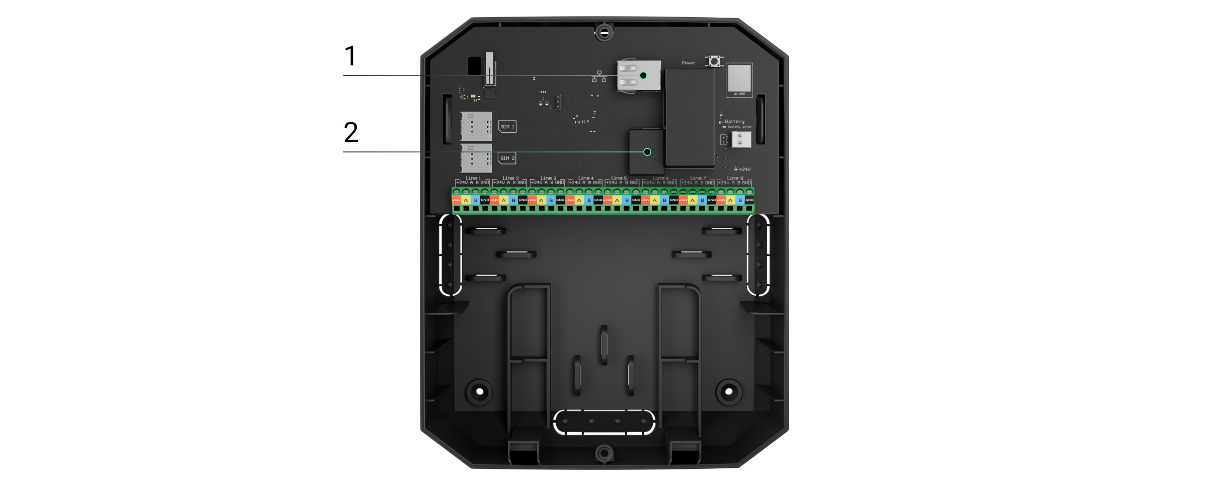
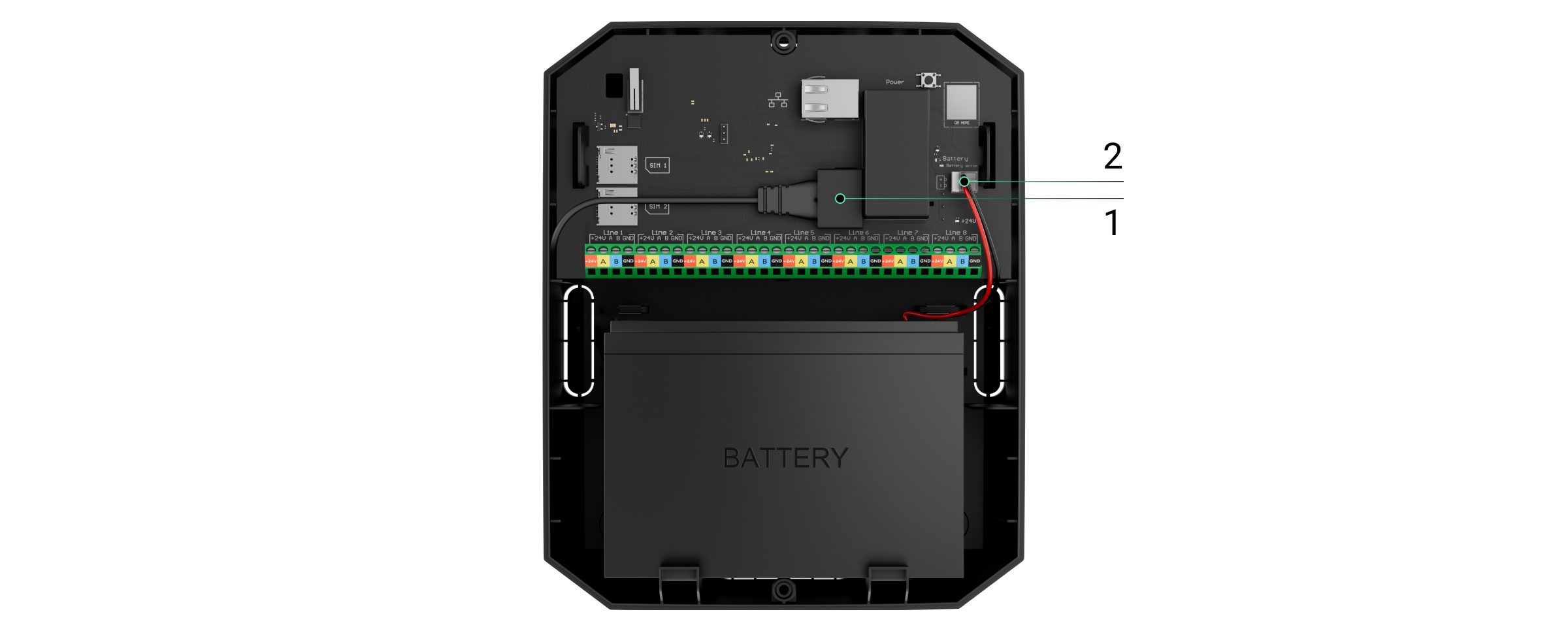
- Conecte o cabo de alimentação e os cabos Ethernet aos conectores apropriados:
1 — Conector do cabo Ethernet.
2 — Conetor do cabo de alimentação. - Instale cartões SIM:
1 — o primeiro slot de micro-SIM.
2 — o segundo slot para micro SIM. - Conecte uma bateria de reserva de 12 V⎓ com uma capacidade de 4, 7 ou 9 A∙h. A carcaça do hub foi concebida para ser utilizada com este tipo de bateria.
- Mantenha premido o botão de alimentação do hub. Assim que o hub estiver ligado, os LEDs da linha Fibra na placa do hub acendem-se.
- Aguarde até que o painel de controlo esteja ligado à Internet. A cor verde ou branca do LED indica que o hub está pronto a funcionar.
Para instalar a placa de Superior Hub Hybrid (4G) revisão 2 (data de fabrico a partir de junho de 2025) em Case D (430), consulte o manual do utilizador de Case para obter orientações de instalação.
Se a ligação Ethernet falhar
Se a ligação Ethernet não for estabelecida, desative a filtragem de endereços proxy e МАС e ative o DHCP nas definições do router. O hub recebe automaticamente um endereço IP. Depois disso, pode atribuir um endereço IP estático ao hub na app Ajax.
Se a ligação do cartão SIM falhar
Para se ligar à rede móvel, é necessário instalar um cartão micro SIM com um pedido de código PIN desativado e um montante de fundos suficiente na conta para pagar os serviços de acordo com a tarifa do operador. Para desativar o pedido de código PIN, insira o cartão SIM no telemóvel.
Se o hub não conseguir ligar-se à rede celular, utilize a Ethernet para configurar os parâmetros de rede: roaming, ponto de acesso APN, nome de utilizador e palavra-passe. Para conhecer estes parâmetros, contacte o serviço de apoio do seu operador móvel.
Adicionar um hub à versão PRO da app
Utilize as versões mais recentes das apps Ajax para aceder a todas as funcionalidades disponíveis e garantir o funcionamento adequado do sistema. Superior Hub Hybrid só pode ser adicionado e configurado em apps Ajax PRO.
Depois de adicionar um hub à sua conta, passa a ser o administrador do dispositivo. Os administradores podem convidar outros utilizadores para o sistema e determinar os seus direitos. Pode ligar até 50 utilizadores ao Superior Hub Hybrid.
Cada conta PRO ligada ao hub, bem como o perfil da empresa de segurança, é considerada um utilizador do sistema.
Alterar ou remover o administrador da lista de utilizadores do hub não repõe as definições do sistema ou dos dispositivos ligados.
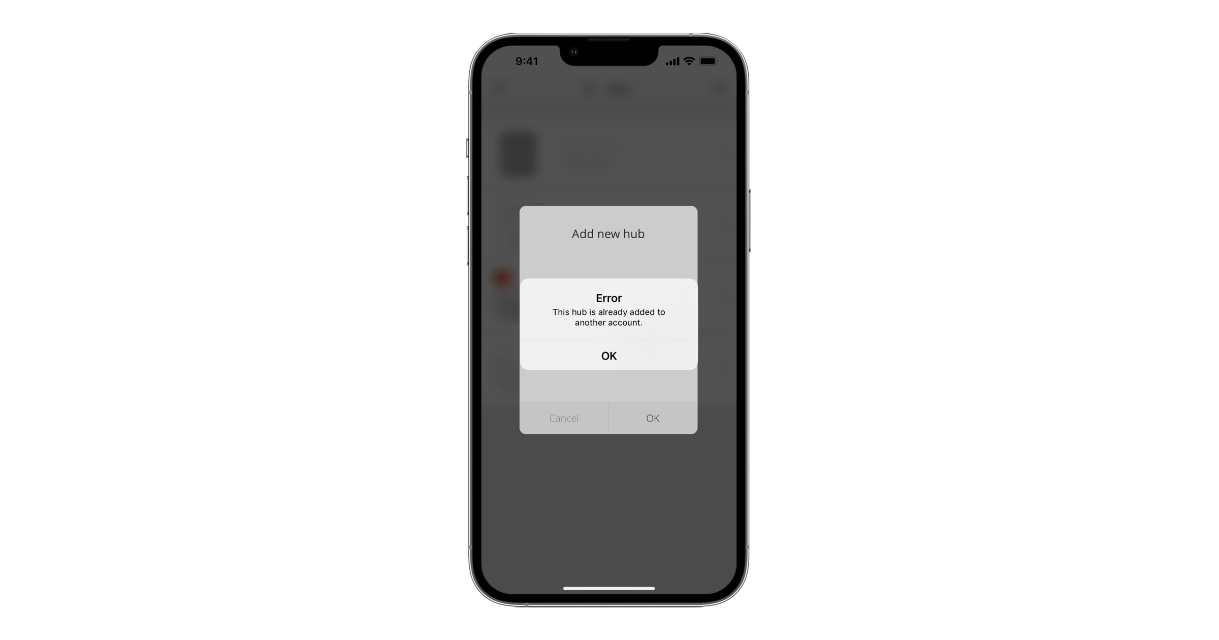
Se já existirem utilizadores no hub, o administrador do hub, o PRO com todos os direitos ou a empresa de instalação do hub selecionado pode adicionar a sua conta ao mesmo. Receberá uma notificação de que o hub já foi adicionado a outra conta.
Contacte o nosso Apoio Técnico para determinar quem tem direitos de administrador no hub.
Adicionar um hub à versão PRO da app:
- Conecte a alimentação externa, bateria de reserva, Ethernet e/ou cartões SIM ao hub.
- Ligue o hub e aguarde até que o indicador LED de estado da conexão se acenda a verde ou branco.
- Abra a versão PRO da app. Permita que a app aceda às funcionalidades solicitadas. Isto irá permitir-lhe utilizar totalmente as capacidades da app Ajax e não perder notificações sobre alarmes ou eventos.
- Assegure-se de que tem um espaço. Crie o espaço se não o tiver.
A funcionalidade de espaço está disponível para apps dessas versões e superiores:
- Ajax Security System 3.0 para iOS;
- Ajax Security System 3.0 para Android;
- Ajax PRO: Tool for Engineers 2.0 para iOS;
- Ajax PRO: Tool for Engineers 2.0 para Android;
- Ajax PRO Desktop 4.0 para macOS;
- Ajax PRO Desktop 4.0 para Windows.
- Clique em Adicionar Hub.
- Escolha um método adequado: manualmente ou utilizando um guia passo-a-passo. Se estiver a configurar o sistema pela primeira vez, utilize o guia passo a passo.
Se selecionou a adição manual
- Atribua o nome do hub.
- Digitalize o código QR ou introduza o ID manualmente.
- Aguarde até que o hub seja adicionado. Após a ligação, o hub será apresentado no menu Dispositivos
da versão PRO da app.
Se escolheu um guia passo a passo
Siga as instruções na app. Após a conclusão, o hub e os dispositivos ligados serão apresentados no menu Dispositivos da versão PRO da app.
Contador de falhas
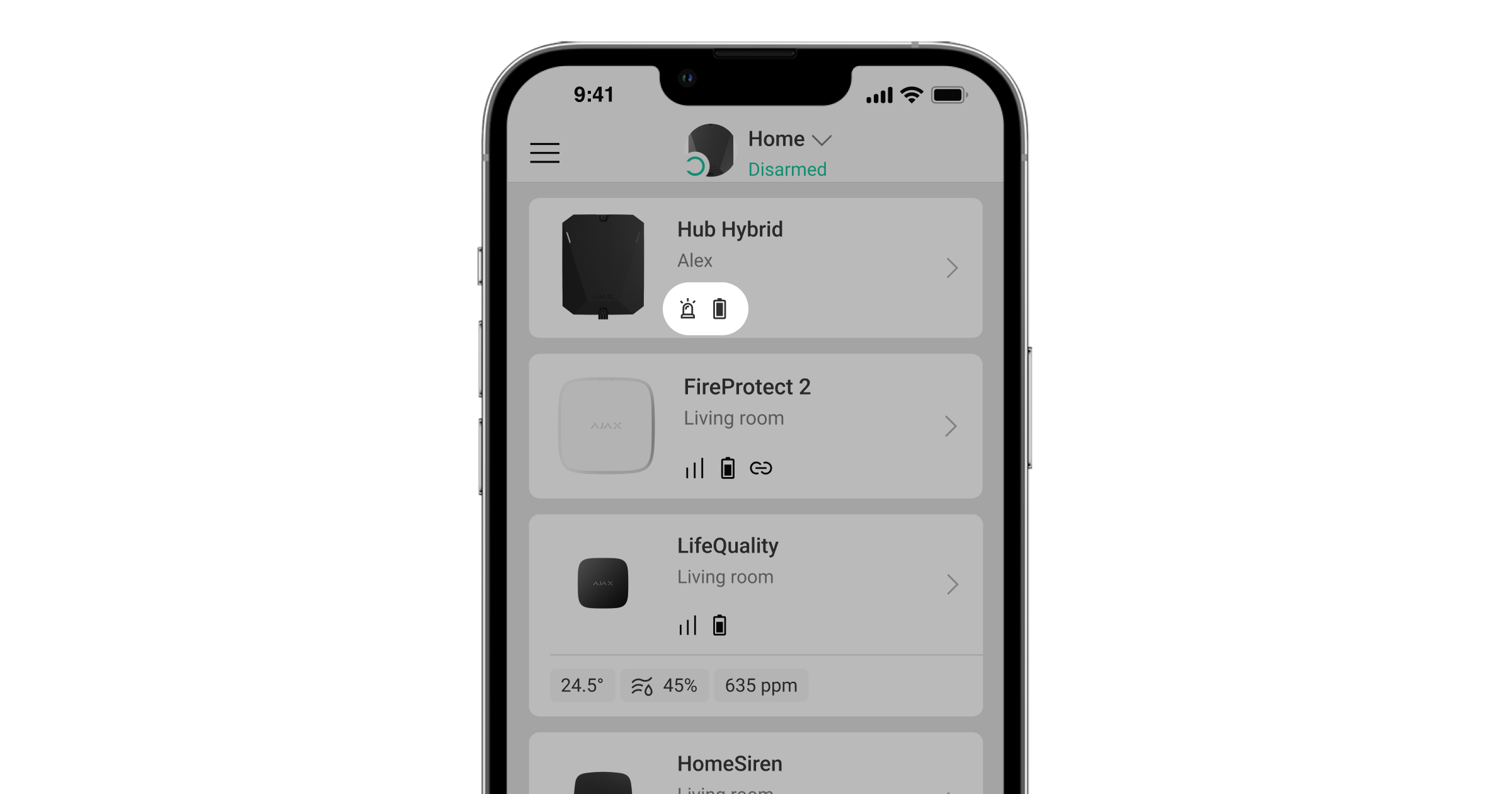
Se for detetada uma falha no hub (por exemplo, não está disponível uma fonte de alimentação externa), o contador de falhas é apresentado no ícone do dispositivo na app Ajax.
Todas as falhas podem ser visualizadas nos estados do hub. Os campos com falhas serão destacados a vermelho.
Ícones do hub
Os ícones apresentam alguns dos estados do Superior Hub Hybrid. Pode vê-los na app Ajax, no separador Dispositivos .
| Ícone | Significado |
| O hub funciona na rede 2G. | |
|
O hub funciona na rede 3G. Disponível apenas para o Superior Hub Hybrid (4G). |
|
|
O hub funciona na rede 4G (LTE). Disponível apenas para o Superior Hub Hybrid (4G). |
|
| Sem cartões SIM. Introduza pelo menos um cartão SIM. | |
| O cartão SIM está defeituoso ou tem um código PIN configurado. Verifique o funcionamento do cartão SIM no telemóvel e desative o pedido de código PIN. | |
| Nível de carga da bateria do Superior Hub Hybrid. Apresentado em incrementos de 1%. | |
| A bateria de reserva não está ligada. | |
| Detetada uma avaria no Superior Hub Hybrid. Abra os estados do hub para mais pormenores. | |
|
O hub está diretamente ligado à central de monitorização da empresa de segurança. O ícone não é apresentado se a ligação direta não estiver disponível ou não estiver configurada. |
|
|
O hub não está diretamente ligado à central recetora de alarmes da empresa de segurança. O ícone não é apresentado se a ligação direta não estiver disponível ou não estiver configurada. |
|
| O hub está no estado Modo de poupança. |
Estados do hub
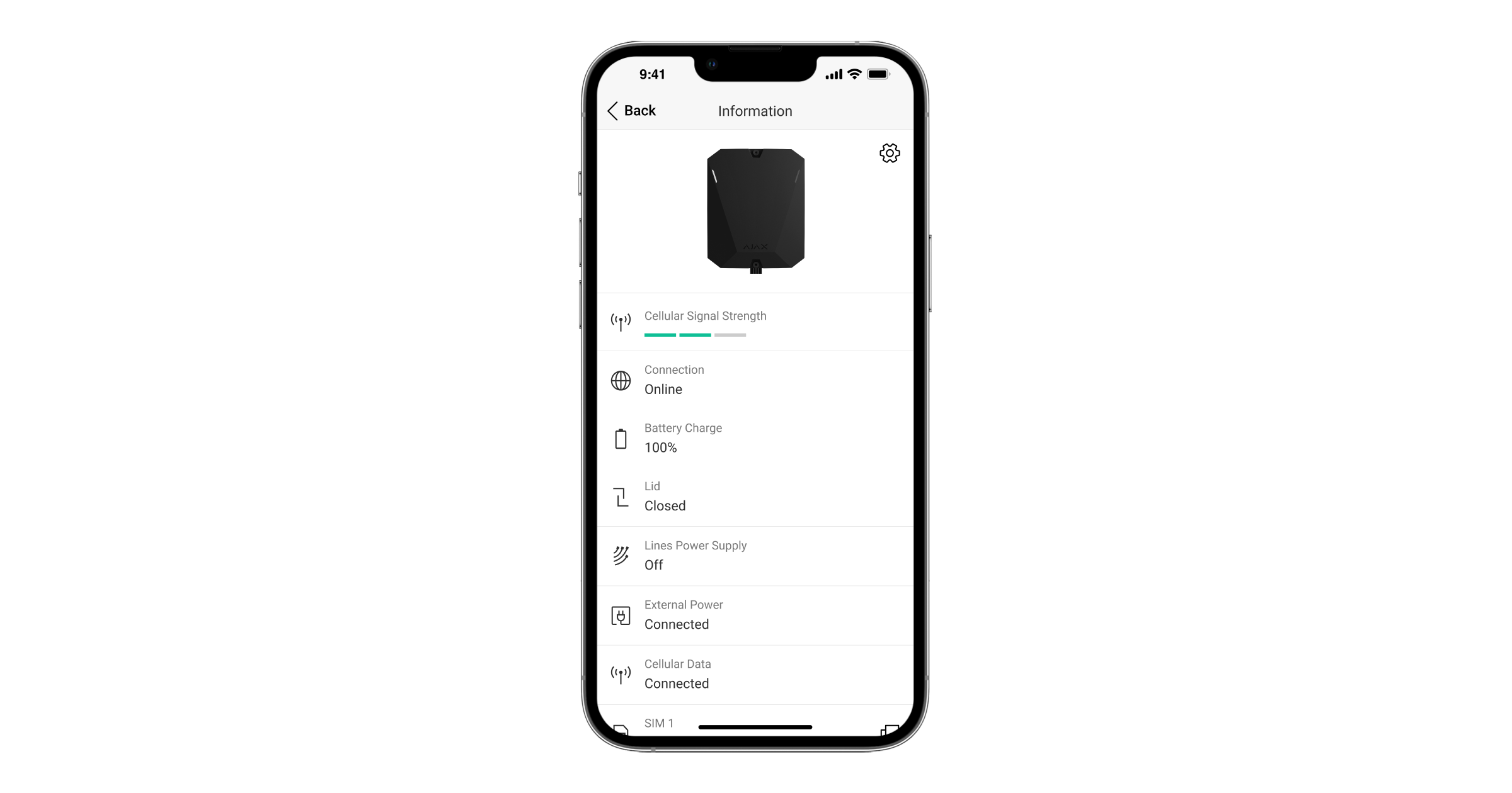
Os estados podem ser encontrados na app Ajax:
- Aceda ao separador Dispositivos
.
- Selecione Superior Hub Hybrid da lista.
| Parâmetro | Significado |
| Avaria |
Clique no botão O campo só aparece se for detetada uma avaria. |
| Intensidade do sinal móvel |
A intensidade do sinal da rede móvel SIM ativa. Instale o hub em locais onde o nível de comunicação móvel atinge 2-3 barras. Se o hub estiver instalado num local com uma intensidade de sinal fraca ou instável, não poderá efetuar uma chamada ou enviar um SMS sobre um evento ou alarme. |
| Ligação | O estado da ligação entre o hub e o Ajax Cloud:
Se o Superior Hub Hybrid não estiver conectado ao servidor, os ícones do hub e todos os dispositivos conectados tornam-se semi-transparentes na lista de dispositivos. |
| Carga da Bateria |
Nível de carga da bateria de reserva do hub. Apresentado em incrementos de 1%. Com um nível de carga de 20% e inferior, o hub informa que a carga da bateria é baixa. |
| Tampa | O estado de tamper que responde à desmontagem ou à abertura da carcaça do painel de controlo:
|
| Fonte de alimentação de linhas | Estado da alimentação nas linhas Fibra do hub:
|
| Alimentação externa | Estado da ligação da fonte de alimentação externa:
|
| Ruído Médio (dBm) |
Ruído médio no canal de rádio. Medido no local onde o hub está instalado. Os dois primeiros valores mostram o nível nas frequências Jeweller, e o terceiro nas frequências Wings. O valor aceitável é — 80 dBm ou inferior. Por exemplo, —95 dBm é considerado aceitável e — 70 dBm é inválido. |
| Dados móveis | Estado da ligação à Internet móvel do hub:
Se a intensidade do sinal de telemóvel atingir 1–3 barras, e o hub tiver fundos suficientes e/ou tiver SMS/chamadas de bónus, será possível efetuar chamadas e enviar SMS, mesmo que este campo apresente o estado Não conectado. |
| Ativo | Apresenta o cartão SIM ativo:
|
| SIM 1 |
O número do cartão SIM instalado na primeira ranhura. Para copiar o número, clique no mesmo. Se o número de telefone for apresentado como um número Desconhecido, o operador não o gravou na memória do cartão SIM. |
| SIM 2 |
O número do cartão SIM instalado na segunda ranhura. Para copiar o número, clique no mesmo. Se o número de telefone for apresentado como um número Desconhecido, o operador não o gravou na memória do cartão SIM. |
| Ethernet | Estado da ligação à Internet do hub via Ethernet:
|
| Estação de Monitorização | O estado da ligação direta do hub à central recetora de alarmes da empresa de segurança:
Se este campo for apresentado, a Empresa de segurança utiliza uma ligação direta para receber eventos e alarmes do sistema de segurança. |
| Ativação programada |
Disponível com OS Malevich 2.31 e versões posteriores. O estado da funcionalidade de ativação programada. Toque no ícone Os estados disponíveis são:
|
| Modelo de Hub |
Designação do modelo do hub: Superior Hub Hybrid (2G) ou Superior Hub Hybrid (4G). |
| Versão do firmware | Versão de hardware do Superior Hub Hybrid. Não atualizado. |
| Firmware |
Versão do firmware do Superior Hub Hybrid. Atualizações remotas. |
| ID do dispositivo |
Identificador (primeiros 8 dígitos do número de série) do Superior Hub Hybrid. O identificador está localizado na caixa do dispositivo e na placa sob o código QR. |
| IMEI | Um número de série único de 15 dígitos para identificar o modem do hub numa rede GSM. É apresentado apenas quando um cartão SIM está instalado no hub. |
Seleção do local de instalação
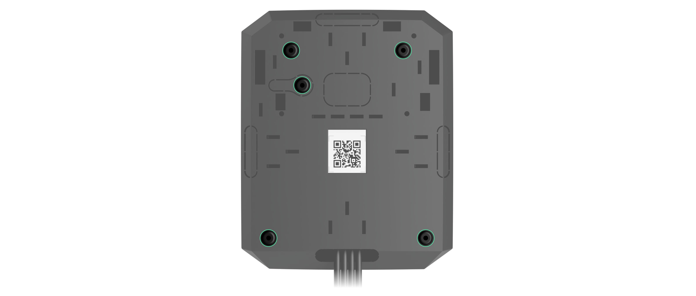
Fixe a carcaça do Superior Hub Hybrid numa superfície vertical utilizando os fixadores incluídos. Todos os furos necessários para a fixação na carcaça já foram feitos.
A fixação vertical do hub é necessária para que o tamper responda se alguém tentar retirar um dispositivo. Consulte a documentação da bateria antes de a instalar — algumas baterias só podem ser montadas na vertical (com os terminais para cima). Outra posição de instalação pode causar uma rápida degradação da bateria.
É aconselhável escolher um local de instalação onde o hub esteja escondido de olhares atentos — por exemplo, numa despensa. Isto ajudará a reduzir a probabilidade de sabotagem ou de inibição no sistema de segurança. Note que o aparelho se destina apenas a instalação no interior.
Escolha um local onde o hub possa ser ligado através de todos os canais de comunicação possíveis: Ethernet e dois cartões SIM. A intensidade do sinal de telemóvel no local de instalação deve ser estável e atingir 2-3 barras. Não garantimos o funcionamento correto do dispositivo com uma intensidade de sinal móvel baixa.
Ao escolher um local de instalação, tenha em conta a distância entre o hub e os dispositivos sem fios e a presença de obstáculos entre eles que dificultem a passagem do sinal de rádio: paredes, pisos intermédios ou objetos de grandes dimensões localizados na divisão.
Para calcular aproximadamente a intensidade do sinal no local de instalação, utilize o nosso Calculador de alcance das comunicações via rádio. Utilize o Calculador de fonte de alimentação Fibra para calcular o alcance da ligação com fios.
Faça os testes de intensidade do sinal Jeweller, Wings e Fibra. A intensidade de sinal estável de 2-3 barras com todos os dispositivos ligados deve ser fornecida no local de instalação escolhido. Com uma intensidade do sinal de 1 ou 0 barras, não garantimos o funcionamento estável do sistema de segurança.
Se o sistema tiver dispositivos com intensidade de sinal de 1 ou 0 barras, considere a deslocação do hub ou do dispositivo. Se tal não for possível ou se o dispositivo continuar a ter uma intensidade de sinal baixa ou instável depois de ser deslocado, utilize repetidores.
Instalação do painel de controlo
Durante a instalação e o funcionamento do sistema de segurança Ajax, cumpra as regras e os requisitos dos atos jurídicos regulamentares sobre segurança elétrica. Não desmonte o dispositivo enquanto este estiver sob tensão ou utilize o com um cabo de alimentação danificado.
Antes da instalação, certifique-se de que selecionou o local ideal para o dispositivo e que este cumpre os requisitos deste manual.
Para instalar o Superior Hub Hybrid na carcaça padrão:
- Prepare previamente as saídas dos cabos, partindo cuidadosamente as partes perfuradas da carcaça do Superior Hub Hybrid.
- Fixe a carcaça na superfície vertical no local de instalação escolhido com os parafusos incluídos, utilizando todos os pontos de fixação. Um deles encontra-se na parte perfurada por cima do tamper — é necessário para acionar o tamper no caso de qualquer tentativa de desprender a carcaça do hub.
- Coloque a placa Superior Hub Hybrid na carcaça nos suportes.
- Conecte a bateria de reserva de 12 V⎓. Não ligue fontes de alimentação de terceiros. Isto pode resultar numa falha do painel de controlo.
Utilize uma bateria de 12 V⎓ com uma capacidade de 4, 7 ou 9 A∙h. As dimensões máximas da bateria a instalar na carcaça são 151 × 65 × 94 mm e o peso é de 5 kg. Suportes especiais são fornecidos para esta configuração de bateria na carcaça do hub. Pode utilizar baterias de capacidade diferente, desde que tenham o tamanho adequado e o tempo de carregamento não exceda 40 horas. A corrente máxima de carregamento da bateria a partir do Superior Hub Hybrid é de 300 mA.
- Ligue o hub.
- Instale a tampa na carcaça do hub e fixe-a com os parafusos incluídos.
- Verifique o estado da carcaça do hub na versão PRO da app. Se a app mostrar alarme de tamper, verifique o aperto da carcaça do Superior Hub Hybrid.
Para instalar a placa de Superior Hub Hybrid (4G) revisão 2 (data de fabrico a partir de junho de 2025) em Case D (430), consulte o manual do utilizador de Case para obter orientações de instalação.
Não instale o hub
No exterior. Isto pode resultar numa falha do painel de controlo.
Perto dos objetos metálicos e dos espelhos. Podem causar atenuação ou blindagem do sinal de rádio. Isto pode resultar na perda de ligação entre o hub e os dispositivos Ajax sem fios.
Em locais com elevados níveis de interferências radioelétricas. Esta situação pode resultar na perda de ligação entre o hub e os dispositivos Ajax sem fios ou em notificações falsas sobre inibição no sistema de segurança.
A menos de 1 metro de distância do router e cabos de alimentação. Isto pode resultar na perda de ligação entre o hub e os dispositivos sem fios.
A menos de 1 metro de distância de dispositivos Jeweller. Isto pode resultar na perda de ligação entre o hub e estes dispositivos.
Em locais onde o hub terá uma intensidade de sinal de 1 ou 0 barras com dispositivos ligados. Isto pode resultar na perda de ligação entre o hub e estes dispositivos.
Dentro de instalações com temperatura e humidade fora dos limites permitidos. Isto pode resultar numa falha do painel de controlo.
Em locais sem sinal móvel ou com 1 barra de intensidade do sinal. Não garantimos o funcionamento correto do dispositivo com uma intensidade de sinal móvel baixa.
Preparação para conectar dispositivos
Crie pelo menos uma sala virtual antes de adicionar dispositivos ao sistema. As salas são necessárias para agrupar dispositivos e aumentar o conteúdo informativo das notificações. Os nomes dos dispositivos e das salas são apresentados no texto dos eventos e alarmes do sistema de segurança Ajax.
Ligação de dispositivos sem fios
O hub é incompatível com outros hubs, uartBridge e ocBridge Plus.
Para adicionar um dispositivo ao hub, na versão PRO da app:
- Abra a sala e selecione Adicionar Dispositivo.
- Dê um nome ao dispositivo, leia ou introduza manualmente o seu código QR, selecione um grupo se o modo de grupo estiver ativado.
- Clique em Adicionar — começa a contagem decrescente para adicionar um dispositivo.
- Siga as instruções na app para ligar o dispositivo.
- Repita os passos 1-4 para adicionar quaisquer dispositivos necessários.
Para emparelhar (ligar) um dispositivo ao hub, o dispositivo deve estar localizado dentro do alcance de comunicação por rádio do hub — nas mesmas instalações protegidas.
Conexão de dispositivos com fios
O hub é incompatível com outros hubs, uartBridge e ocBridge Plus.
A tecnologia de comunicação por cabo Fibra permite criar segmentos até 2000 metros de comprimento. Até 8 segmentos num único sistema sob controlo Superior Hub Hybrid.
Superior Hub Hybrid de 8 linhas compatível com todos os dispositivos Fibra, independentemente do tipo. Os detetores de segurança, os teclados e as sirenes estão ligados à mesma linha e garantem a segurança de uma área específica das instalações.
Conceção e preparação
Para que o sistema funcione bem, é crucial planear o projeto adequadamente e instalar todos os dispositivos corretamente. O não cumprimento das regras básicas de instalação e das recomendações do manual do utilizador pode resultar num funcionamento incorreto ou na perda de ligação entre o hub e os dispositivos instalados.
Ao conceber o esquema de disposição dos detetores, tenha em conta o esquema de ligação dos cabos elétricos instalados no local. Os cabos de sinal dos dispositivos Fibra devem ser colocados a uma distância mínima de 50 cm dos cabos de alimentação, quando colocados paralelamente, e, em caso de intersecção, a um ângulo de 90°.
No total, é possível ligar até 100 dispositivos Ajax ao Superior Hub Hybrid. O rácio de dispositivos com e sem fios no sistema não tem importância. Por exemplo, pode ligar 50 dispositivos com fios e 50 dispositivos sem fios ou 99 dispositivos com fios e 1 dispositivo sem fios.
Nas instalações em construção ou renovação, os cabos dos dispositivos com fios são colocados após a cablagem principal da instalação. Utilize tubos de proteção para encaminhar os cabos dos dispositivos com fio para organizar e fixá-los; laços, clipes e agrafos podem ser usados para fixá-los.
Sempre que possível, evitar danos externos nos cabos. Quando colocar fios no exterior (sem os montar no interior das paredes), utilize uma calha de canalização elétrica. As calhas não devem estar cheias com mais de metade dos cabos. Não deixe que os cabos se desprendam. A calha deve ser escondida da vista, se possível — por exemplo, atrás de móveis.
Recomendamos a colocação de cabos no interior de paredes, pavimentos e/ou tetos. Esta medida garante uma maior segurança: os fios não serão visíveis, será impossível danificá-los acidentalmente e será impossível a um intruso aceder-lhes.
Ao selecionar um cabo, tenha em conta o comprimento das linhas de ligação e o número de dispositivos a serem conectados; esses parâmetros afetam a intensidade do sinal. Recomendamos a utilização de cabos de cobre blindados com uma camada de isolamento de alta qualidade. Verifique os cabos quanto a dobras e danos físicos antes da instalação.
Durante a instalação, respeite o raio de curvatura indicado pelo fabricante nas especificações do cabo. Caso contrário, corre-se o risco de danificar ou partir o condutor. O raio de curvatura é especificado pelo fabricante nas especificações do cabo.
Intensidade do sinal e comprimento do cabo
O nível do sinal Fibra é determinado pelo número de pacotes de dados não entregues ou corrompidos durante um determinado período. A intensidade do sinal é apresentada pelo ícone no separador Dispositivos
:
- Três barras — excelente intensidade do sinal.
- Duas barras — boa intensidade do sinal.
- Uma barra — fraca intensidade do sinal, não é garantido um funcionamento estável.
- Ícone riscado — sem sinal.
A intensidade do sinal é influenciada pelos seguintes fatores: o número de dispositivos ligados a uma linha, o comprimento e o tipo de cabo e a ligação correta dos fios aos terminais dos dispositivos.
O comprimento máximo do cabo depende do tipo de cabo, do material e do método de ligação dos dispositivos. Quando ligado através da ligação de feixe (cablagem radial) (hub – dispositivos – resistência de terminação) utilizando o par entrançado U/UTP cat.5 (4×2×0,51), o comprimento da ligação com fios pode atingir os 2000 metros. O comprimento mínimo do cabo para ligar dispositivos com fios é de 1 metro.
Quando ligado através do método de ligação em anel (hub – dispositivos – hub), o comprimento máximo do cabo é de 500 metros no caso de utilização de um par entrançado.
Topologia em anel está disponível com OS Malevich 2.16 e superior.
Instalação e conexão
Antes de instalar os detetores e os dispositivos, certifique-se de que selecionou o local ideal e que este cumpre as condições do manual do utilizador. Os fios devem ser escondidos da vista e localizados num local de difícil acesso para os intrusos, de modo a reduzir a probabilidade de sabotagem. Idealmente, os fios devem ser colocados nas paredes, no chão e/ou no teto. Antes da instalação final, teste a intensidade do sinal Fibra.
Ligue os dispositivos ao hub utilizando um cabo de quatro fios. Dois fios fornecem energia ao dispositivo (+24 V e GND), e os outros (A e B) são utilizados para a troca de dados entre os dispositivos conectados e o hub. Ao conectar, certifique-se de observar a polaridade e a ordem de conexão dos fios.
Os dispositivos são ligados ao hub através de duas topologias de ligação: Anel e Feixe (Cablagem radial). Os dispositivos são ligados à linha Fibra um a um, como mostra a figura.

Recomendamos que distribua os dispositivos com fios uniformemente por todas as linhas Fibra do hub para aumentar a fiabilidade.
Recomendamos a ligação de dispositivos com fios através do método de ligação em anel. Se a linha for interrompida, os dispositivos continuarão a estar ligados ao Superior Hub Hybrid através da ligação de Feixe (Cablagem Radial) e continuarão a transmitir eventos e alarmes para o hub. A notificação sobre a falha de linha aberta será enviada aos utilizadores e à empresa de segurança.
Quando ligar através do Método de ligação por anel, ligue duas linhas por segmento e reduza o comprimento máximo da ligação com fios para 500 metros (quando ligado através do método de ligação por Feixe (cablagem Radial) — para 2000 metros).
| Feixe (Cablagem radial) | Anel |
|
|
Topologia em anel está disponível com OS Malevich 2.16 e superior.
Ao ligar dispositivos, não torça os fios entre si; solde-os. As extremidades dos fios que serão inseridos nos terminais da sirene devem ser estanhadas para aumentar a confiabilidade da conexão.
Respeite a polaridade e a ordem de conexão dos fios. Fixe firmemente os fios aos terminais. Se o corpo do dispositivo fornecer fixadores para cabos, prenda o cabo com amarras.
Para conectar um detetor ou dispositivo:
- Corte a energia e desligue o hub. Desconecte a bateria de reserva.
1 — Fonte de alimentação externa
2 — Bateria de reserva - Passe os cabos de quatro fios para dentro do hub. Conecte os fios aos terminais da linha do Superior Hub Hybrid:
+24V — terminal de alimentação elétrica de 24 V⎓.
A, B — terminais de sinal.
GND — terra. - Conecte a outra extremidade do cabo de quatro fios aos terminais do primeiro dispositivo na linha, respeitando a polaridade e a ordem de ligação. Fixe firmemente o cabo aos terminais do dispositivo.
- Se outros dispositivos estiverem conectados ao segmento, prepare e conecte o cabo para o dispositivo seguinte nos terminais.
+24V — terminal de alimentação elétrica de 24 V⎓.
A, B — terminais de sinal.
GND — terra. - Conecte outros dispositivos à linha, se necessário.
- Instale uma resistência de terminação de 120 ohm para o último dispositivo na linha utilizando a topologia de Feixe (Radial). É instalada uma resistência de terminação entre os terminais A e B do último dispositivo da linha.
Com a topologia em Anel, não é necessária uma resistência de terminação. Neste caso, ligue o último dispositivo da linha à linha Fibra seguinte do hub.
O valor nominal das resistências de terminação é de 120 Ω. As resistências de terminação estão incluídas no conjunto completo do Superior Hub Hybrid.
Topologia em anel está disponível com OS Malevich 2.16 e superior.
- Conecte a alimentação ao hub e ligue-o.
- Adicione dispositivos ao sistema manualmente ou utilizando a leitura de linha.
- Efetue o teste de intensidade do sinal Fibra para cada dispositivo ligado. A intensidade de sinal recomendada é de duas ou três barras. Caso contrário, verifique a conexão e integridade dos fios ou mude de local os dispositivos do sistema.
Adicionar dispositivos com fios
Existem duas formas de adicionar dispositivos com fios: manualmente e utilizando a digitalização da linha. É útil adicionar alguns dispositivos manualmente — por exemplo, quando se substitui um detetor defeituoso por um novo. A digitalização automática de linha é útil ao adicionar inúmeros dispositivos.
Para adicionar um dispositivo com fios manualmente:
- Abra a versão PRO da app.
- Selecione o objeto ao qual pretende adicionar o dispositivo.
- Aceda ao separador Dispositivos
e clique em Adicionar dispositivo.
- Dê um nome ao dispositivo, leia ou escreva o código QR (disponível no corpo do dispositivo e na embalagem), selecione uma sala e um grupo (se o modo de grupo estiver ativado).
- Clique em Adicionar.
Para adicionar dispositivos utilizando digitalização de linha:
- Abra a versão PRO da app.
- Selecione o objeto ao qual pretende adicionar o dispositivo.
- Aceda ao separador Dispositivos
.
- Clique em Adicionar dispositivo.
- Clique em Adicionar todos os dispositivos Fibra.
- O hub iniciará o processo de digitalização de linha.
Após a digitalização da linha, a app PRO apresentará uma lista de dispositivos com fios conectados ao hub. Os dispositivos na lista são ordenados por linhas às quais estão fisicamente ligados. Pode encontrar o dispositivo introduzindo parte do nome, modelo ou ID no campo de pesquisa.
Por defeito, a designação do dispositivo inclui o seu nome e ID. Para emparelhar um dispositivo com o hub, editar o seu nome, atribuí-lo a uma sala e a um grupo se o modo de grupo estiver ativado.
A digitalização também está disponível no menu de Linhas (Hub → Definições → Linhas → Adicionar Todos os Dispositivos Fibra).
Para que o técnico de instalação possa nomear corretamente o dispositivo ou atribuir-lhe uma sala e um grupo, previmos dois métodos de identificação do dispositivo: por indicação LED e por alarme.
Método 1: Identificar o dispositivo através da intermitência
Após a leitura da linha, a app PRO apresentará uma lista de dispositivos com fios conectados ao hub.
Clique em qualquer dispositivo desta lista. Depois de clicar, o indicador LED do dispositivo começará a piscar. Depois de identificar o dispositivo, associe-o ao hub.
Para emparelhar um dispositivo a um hub:
- Clique no dispositivo na lista.
- Dê um nome ao dispositivo.
- Especifique uma sala e um grupo se o modo de grupo estiver ligado.
- Clique em Guardar.
- O dispositivo emparelhado desaparecerá da lista de dispositivos disponíveis para adicionar.
Método 2: Adicionar dispositivos por alertas
Selecione a opção Prioritizar dispositivos acionados.
Acionar um alarme. Por exemplo, passe em frente de um detetor de movimentos, prima qualquer botão do teclado ou acione uma sirene.
Quando acionado, o detetor passa para o topo da lista, para a categoria Dispositivos acionados recentemente. O dispositivo permanecerá nesta categoria por 5 segundos, e depois voltará para a categoria Linha. Depois de identificar o dispositivo, associe-o ao hub.
Para emparelhar um dispositivo a um hub:
- Clique no dispositivo na lista.
- Dê um nome ao dispositivo.
- Especifique uma sala e um grupo se o modo de grupo estiver ativado.
- Clique em Guardar.
- O dispositivo emparelhado desaparecerá da lista de dispositivos disponíveis para adicionar.
A atualização dos estados dos dispositivos com fios depende do período de ping (ajusta-se nas definições Jeweller/Fibra).
Se o hub já tiver o número máximo de dispositivos adicionados (para o Superior Hub Hybrid, a predefinição é 100), receberá uma notificação de erro quando adicionar um.
Dispositivos Ajax conectados funcionam com apenas um hub. Uma vez adicionados a um novo hub, estes dispositivos não são removidos da lista de dispositivos do hub antigo. Esta operação deve ser efetuada através da app Ajax PRO.
Definições do hub
As definições do painel de controlo podem ser alteradas nas app Ajax PRO. Para alterar as definições:
- Inicie sessão na versão PRO da app.
- Selecione um objeto da lista.
- Aceda ao menu Dispositivos.
- Selecione o hub.
- Aceda às suas Definições clicando no ícone de engrenagem
.
- Selecione uma categoria de definições e efetue alterações. Após efetuar as alterações, clique em Voltar para guardar as novas definições.
O nome do hub é apresentado no texto do SMS e da notificação push. O nome pode conter até 12 caracteres cirílicos ou até 24 caracteres latinos.
Para o alterar, clique no ícone de lápis e introduza o novo nome do hub.
Seleção da sala virtual do hub. O nome da sala é apresentado no texto do SMS e da notificação push.
Definições para a ligação à Internet com fios.
- Ethernet — ativa e desativa o módulo Ethernet do hub.
- DHCP / Estático — seleção de um método para o hub obter um endereço IP. Se DHCP for selecionado, o hub obtém automaticamente um endereço IP e outras definições de rede. Estático permite-lhe configurar manualmente o endereço IP e outras definições de rede para o hub.
- Endereço IP — endereço IP do hub.
- Máscara de sub-rede — máscara da sub-rede em que o hub funciona.
- Porta de entrada — porta de entrada utilizada pelo hub.
- DNS — DNS do hub.
Definições da rede móvel e dos cartões SIM instalados. No menu principal, pode editar as definições relativas a ambos os cartões SIM e, no submenu, os parâmetros privados dos cartões SIM.
Definições do menu principal
Dados móveis — desativa e ativa o módulo móvel do hub.
Roaming — se esta opção estiver ativa, os cartões SIM podem funcionar em roaming.
Ignorar erro de registo de rede — se esta opção estiver ativa, o hub ignora os erros ao tentar conectar-se à rede através de um cartão SIM. Ative esta opção se o cartão SIM não conseguir ligar-se à rede.
Desativar a verificação da comunicação com o operador — se esta opção estiver ativa, o hub ignora os erros de comunicação do operador. Ative esta opção se o cartão SIM não conseguir ligar-se à rede.
SIM 1 — apresenta o número do cartão SIM instalado. Se o número de telefone for apresentado como um Número desconhecido, o operador não o gravou na memória do cartão SIM. Clicar no campo abre as definições deste cartão SIM.
SIM 2 — apresenta o número do cartão SIM instalado. Se o número de telefone for apresentado como um Número desconhecido, o operador não o gravou na memória do cartão SIM. Clicar no campo abre as definições deste cartão SIM.
Definições do submenu do cartão SIM
APN, Nome de utilizador, e Palavra-passe — definições para ligar à Internet através de um cartão SIM. Para saber as definições do seu operador de telemóvel, contacte o serviço de apoio do seu fornecedor. As definições APN só são aplicadas após uma ligação bem sucedida com novos parâmetros. Se a tentativa de ligação falhar, o hub continua a funcionar com as definições APN anteriores.
Utilização de dados móveis. O menu contém informações sobre o tráfego móvel utilizado pelo sistema de segurança Ajax, permitindo-lhe repor as estatísticas e verificar o saldo do cartão SIM.
Os dados são calculados no hub e podem diferir das estatísticas do operador. Isto deve-se ao facto de cada operador calcular o tráfego de entrada e de saída individualmente.
Entrada — a quantidade de dados recebidos pelo hub. Apresentado em KB ou MB.
Saída — a quantidade de dados enviados pelo hub. Apresentado em KB ou MB.
Repor estatísticas — repõe as estatísticas do tráfego de entrada e de saída.
Código USSD. Neste campo introduza o código utilizado para verificar o saldo. Por exemplo, *111#. Para enviar um pedido, depois de introduzir o código, clique em Verificar saldo. O resultado do pedido será apresentado por baixo do botão de controlo do saldo.
Definição de palavras-passe de teclado para pessoas que não estão registadas no sistema.
Com a atualização do OS Malevich 2.13.1, adicionámos também a possibilidade de criar uma palavra-passe para as pessoas que não estão ligadas ao hub. Isto é conveniente, por exemplo, para dar a uma empresa de limpeza acesso à gestão da segurança. Sabendo o código de acesso, basta introduzi-lo no teclado Ajax para armar ou desarmar o sistema.
Para definir um código de acesso para uma pessoa não registada no sistema
- Prima Adicionar código.
- Configure o Nome de utilizador e o Código de acesso.
- Prima Adicionar.
Se pretender configurar um código de coação, alterar um código de acesso, definições de acesso a grupos, Modo noturno, ID do código, desativar temporariamente ou eliminar este código, selecione-o na lista e efetue as alterações.
Os códigos de acesso criados são válidos para todos os teclados ligados ao hub. O Superior Hub Hybrid suporta até 50 códigos de acesso.
O Superior Hub Hybrid suporta mais de 1 000 000 variações de códigos PIN.
Esta definição só está disponível em apps Ajax PRO
Defina os requisitos para o comprimento dos códigos de acesso que são utilizados para a autorização e acesso dos utilizadores ao sistema. Pode selecionar a opção Flexível (4 a 6 símbolos) ou definir o comprimento de código fixo: 4 símbolos, 5 símbolos ou 6 símbolos.
Nota: quando se define o comprimento fixo do código, o sistema repõe todos os códigos de acesso configurados anteriormente.
O comprimento do código fixo é necessário para a função de Gestão fácil do Modo Armado que permite desarmar o sistema sem premir o botão Desarmar no teclado depois de introduzir um código de acesso ou utilizar um dispositivo de acesso.
Definições de ativação/desativação programadas. O horário de segurança pode ser utilizado para grupos individuais e para todo o objeto, bem como para o Modo Noturno.
Inicia o Teste da Zona de Deteção para os detetores ligados. O teste permite verificar o funcionamento dos dispositivos e a sua zona de deteção de alarmes.
Definição do período de consulta entre o hub e os dispositivos conectados. As definições indicam a frequência com que o hub comunica com os dispositivos e a rapidez com que é detetada uma perda de conexão.
Intervalo de ping do detetor, seg — a frequência de consulta dos dispositivos conectados pelo hub, definida no intervalo de 12 a 300 segundosO valor predefinido é de 36 segundos. Configurado para dispositivos com e sem fios.
Número de pings falhados para determinar a falha de conexão — contador de pacotes não entregues. O valor predefinido é 8 pacotes (configurados separadamente para dispositivos com e sem fios).
Não diminua os valores predefinidos do intervalo de ping e do período de ping, a menos que seja necessário.
O tempo necessário para enviar uma mensagem relativa à perda de ligação entre o hub e o dispositivo é calculado através da seguinte fórmula:
Intervalo de pings do detetor × Número de pings falhados para determinar a falha da ligação
Quanto mais curto for o período de ping, mais rápido o hub saberá sobre os eventos dos dispositivos conectados e os dispositivos receberão comandos do hub. As informações sobre alarmes e sabotagem são transmitidas instantaneamente, independentemente do intervalo de ping. A diminuição do período de ping afetará a duração da bateria dos dispositivos sem fios.
O intervalo de ping limita o número máximo de dispositivos ligados:
| Intervalo | Limite de ligação |
| 12 s | 39 dispositivos |
| 24 s | 79 dispositivos |
| 36 segundos (por defeito) | 100 dispositivos |
Independentemente das definições do período de ping, até 10 sirenes podem ser conectadas ao Superior Hub Hybrid.
Deteção da interferências rádio — as seguintes definições garantem a conformidade do sistema com os requisitos da Grade 3 da EN 50131. Existem duas opções:
- Deteção avançada de interferências rádio.
- Enviar evento de deteção de interferências rádio como alarme — se ativada, a notificação de um alto nível de interferências rádio será enviada como alarme para todos os utilizadores do sistema.
As definições de telefonia só estão disponíveis com o OS Malevich 2.25 e posterior nas apps Ajax PRO.
As definições de telefonia permitem-lhe configurar um hub Ajax para comunicar com uma central recetora de alarmes (CRA) através do protocolo SIP.
No PRO Desktop, pode ser criado e aplicado um modelo de definições de telefonia para poupar tempo na configuração em vários sistemas.
Um grupo de definições para dispositivos Fibra ligados por cabo.
Fonte de alimentação das linhas — Gestão de energia de linhas Superior Hub Hybrid. Quando ativada, é fornecida energia aos dispositivos Fibra. A alimentação está ligada por defeito.
Teste de alimentação das linhas — executa o teste de alimentação das linhas do Superior Hub Hybrid. Simula o consumo máximo de energia possível: os detetores geram alarmes, os teclados são ativados, as sirenes são ligadas.
Se o sistema passar no teste, todos os dispositivos com fios terão energia suficiente em todas as situações.
Durante o teste de potência das linhas, as sirenes com fio ligadas são ativadas.
Adicionar todos os dispositivos Fibra — executa uma verificação das linhas Fibra. A função mostra todos os dispositivos com fios ligados ao hub, de modo a definir rapidamente nomes, grupos e salas.
Grupo de definições de serviços do hub. Estas estão divididas em 2 grupos: definições gerais e definições avançadas.
Definições gerais
Brilho do LED
Ajuste de brilho do indicador LED do hub. Definir no intervalo de 1 a 10. O valor predefinido é 10.
Atualizações de firmware
O menu contém as definições de atualização do firmware do hub.
- Atualização automática do firmware configura as atualizações automáticas do OS Malevich (ativadas por predefinição):
- Se estiver ativado, o firmware é automaticamente atualizado quando estiver disponível uma nova versão. O sistema deve ser desarmado e a alimentação externa deve ser ligada ao hub.
- Se estiver desativado, o sistema não é atualizado automaticamente. Se estiver disponível uma nova versão de firmware, a app oferecerá a atualização do OS Malevich.
- A opção Verificar se há uma nova versão permite verificar manualmente e instalar atualizações de firmware quando disponíveis ou atribuídas ao hub. Esta opção só está disponível quando a definição de atualização automática do firmware está ativada.
Se o firmware do hub estiver desatualizado, poderá ocorrer um erro ao adicionar um dispositivo ao hub. Neste caso, o sistema solicitará ao utilizador que abra a secção Atualização do firmware nas Definições de serviço e verifique se existe uma nova versão do firmware. Se disponível, o utilizador pode prosseguir com uma atualização do firmware por pedido.
Registo do sistema do hub
Esta definição permite-lhe selecionar o canal de transmissão para os registos do hub ou desativar a sua gravação:
- Ethernet — os registos do sistema são transmitidos através da Internet com fios.
- Desativar — o registo está desativado.
Os registos são ficheiros que contêm informações sobre o funcionamento do sistema. Não desative os registos, uma vez que estas informações podem ser úteis em caso de erros no funcionamento do sistema. Os registos são transmitidos apenas via Ethernet.
Atraso nas notificações de perda de energia externa
Definições para o tempo de atraso no envio de uma notificação de perda de energia externa.
É possível selecionar um tempo de atraso de 1 minuto a 1 hora com um intervalo de seleção de 1 minuto.
Disponível para Superior Hub Hybrid com OS Malevich 2.22 ou posterior.
Quantidade de eventos “Enquanto o hub está offline”
Os eventos durante a falha de comunicação com o servidor são registados na memória intermédia do hub e serão entregues às apps Ajax depois de a ligação ser restabelecida.
Esta definição permite-lhe escolher o número dos últimos eventos que o hub irá enviar para as apps Ajax depois de voltar a estar online.
Pode selecionar entre 100 (valor predefinido) e 1000 eventos com um incremento de 50 eventos.
Disponível para Superior Hub Hybrid com OS Malevich 2.25 ou posterior.
Definições avançadas
Assistente de configuração PD 6662
Abre um guia passo a passo sobre como configurar o seu sistema para cumprir a norma de segurança britânica PD 6662:2017.
Ligação ao servidor
Definições de comunicação entre o hub e o servidor Ajax Cloud:
- Intervalo de Consulta Hub-Servidor, seg. Frequência de envio de pings do hub para o servidor Ajax Cloud. É definido no intervalo de 10 a 300 s. O valor predefinido recomendado é 60 s.
- Atraso do Alarme de Falha de Ligação do Servidor, seg. O atraso é necessário para reduzir o risco de uma notificação falsa de uma conexão perdida com o servidor da Ajax Cloud. Ativado após 3 consultas do servidor do hub sem êxito. O atraso é definido no intervalo de 30 a 600 s. O valor predefinido recomendado é 300 s.
O tempo antes do envio de uma mensagem relativa à perda de comunicação entre o hub e o servidor Ajax Cloud é calculado através da seguinte fórmula:
(Intervalo de ping × 3) + Filtro de tempo
Com as definições predefinidas, o Ajax Cloud comunica a perda do hub em 8 minutos:
(60 s × 3) + 300 s = 8 min
- Receber eventos de perda de ligação ao servidor sem alarme. As apps Ajax podem notificar a perda de ligação ao hub-servidor de duas formas: com um sinal de notificação push padrão ou com um som de sirene (ativado por defeito). Quando a opção está ativa, a notificação vem com um sinal de notificação push padrão.
- Notificar a perda de ligação nos canais. O sistema de segurança Ajax pode notificar os utilizadores e a empresa de segurança sobre a perda de ligação entre o hub e o servidor Ajax Cloud, mesmo através de um dos canais de comunicação.
No menu, é possível selecionar os canais de comunicação através dos quais o sistema notificará a perda de ligação (Ethernet e/ou móvel), bem como o atraso de transmissão dessas notificações. - Atraso de perda da notificação, min — tempo de atraso antes de enviar a notificação sobre a perda de ligação através de um dos canais de comunicação. Definir no intervalo de 3 a 30 minutos.
O tempo de envio de uma notificação sobre a perda de ligação através de um dos canais de comunicação é calculado através da seguinte fórmula:
(Intervalo de ping × 3) + Filtro de tempo + Atraso da notificação.
Sons e Alertas
O menu contém três grupos de definições: parâmetros de ativação da sirene, indicação de pós-alarme da sirene e parâmetros de ativação do sinal sonoro com o teclado.
Parâmetros de ativação da sirene
Se a tampa do hub ou de qualquer detetor estiver aberta. Se estiver ativado, o hub ativa as sirenes ligadas se o corpo do hub, do detetor ou de qualquer outro dispositivo Ajax estiver aberto.
Se o botão de pânico da app for premido. Quando a função está ativa, o hub ativa as sirenes ligadas se o botão de pânico tiver sido premido na app Ajax.
Desativar a resposta da sirene ao premir o botão de pânico do Ajax SpaceControl Jeweller nas definições do comando na app Ajax (Dispositivos → Ajax SpaceControl Jeweller → Definições
).
Ajustes da indicação de pós-alarme da sirene
Esta definição só está disponível em apps Ajax PRO
A sirene pode informar sobre o acionamento do sistema armado por meio da indicação LED. Graças a esta funcionalidade, os utilizadores e as patrulhas das empresas de segurança podem ver que o sistema foi acionado.
Bip com parâmetros de ativação do teclado
Esta definição só está disponível em apps Ajax PRO
Os teclados ligados ao hub emitem um som audível para informar de avarias. Para ativar as notificações sonoras, ative as opções: Se algum dispositivo estiver offline e Se a bateria de algum dispositivo estiver fraca.
As notificações sonoras das avarias estão disponíveis para todos os hubs com a versão de firmware OS Malevich 2.15 ou superior.
As notificações sonoras de avarias são suportadas pelos teclados Ajax com as seguintes versões de firmware ou superiores:
- 5.57.1.1 para KeyPad Jeweller;
- 5.57.5.0 para KeyPad Plus Jeweller;
- 6.57.11.12 para Superior KeyPad Fibra.
Definições da bateria
O menu contém as seguintes definições:
- Poupança de bateria;
- Maximizar a duração da bateria;
- Parar o carregamento da bateria em caso de avaria;
- Notificar se a bateria não carregar.
Esta definição só está disponível em apps Ajax PRO
Poupança de Bateria
A definição Poupar carga da bateria de reserva do hub permite prolongar a vida útil da bateria de reserva quando uma fonte de alimentação externa não está disponível. Quando esta definição está ativada, o hub passa para o modo de espera quando perde a fonte de alimentação externa.
Para poupar a carga da bateria de reserva, o hub desativa os seus canais de ligação (rede móvel, Ethernet, Wi-Fi) quando passa para o modo de espera. Portanto, o hub em modo de espera não está ligado ao Ajax Cloud e à CRA até que ocorra algum evento do sistema. Nas apps Ajax, o hub e os dispositivos adicionados ao mesmo ficarão a cinzento e indisponíveis para configuração ou controlo; o hub estará no estado Modo de poupança de bateria e os dispositivos adicionados ao mesmo ficarão Offline. O espaço na lista de espaços será etiquetado com o estado adicional Modo de poupança.
O modo de espera não afeta o funcionamento do sistema. Qualquer disparo do detetor ativa o hub durante um período de tempo especificado para transmitir o evento aos utilizadores e à CRA. Durante o modo de espera, o LED do hub pisca a vermelho cada 30 segundos e a luminosidade do LED é reduzida ao mínimo.
Se o hub estiver no modo de espera, só é possível mudar os modos de ativação utilizando um teclado ou um comando. A comutação dos modos de ativação do sistema e a configuração do hub no modo de espera através de apps Ajax não são fornecidas.
Ative Poupar carga da bateria de reserva do hub para configurar o tempo de funcionamento do hub:
| Configuração | Significado |
| Período de atividade | O tempo que o hub permanece ligado ao Ajax Cloud após a ocorrência de qualquer evento do sistema está definido para 10 minutos por defeito. No entanto, pode ajustar este tempo de 5 minutos a 1 hora. |
| Intervalo de consulta do servidor | O tempo entre ligações do hub em modo de espera ao servidor está definido para 6 horas por defeito. No entanto, pode ajustar este tempo de 1 hora a 24 horas. |
Pode configurar a data e a hora de saída do hub do Modo de poupança com a funcionalidade de ativação programada.
A funcionalidade está disponível para hubs com OS Malevich 2.31 e versões posteriores e pode ser configurada na lista de estados do hub.
A funcionalidade de Poupança de bateria permite prolongar a vida útil da bateria de reserva até 200 horas para Superior Hub Hybrid (2G) e Superior Hub Hybrid (4G) quando se utiliza uma bateria de reserva de 12 V⎓ com uma capacidade de 7 Ah. Esta duração depende da configuração do sistema e do número de dispositivos adicionados ao hub.
A funcionalidade de Poupança de bateria está disponível para hubs com o OS Malevich 2.19 ou superior.
Quando a função Poupança de bateria está ativada, o sistema não cumpre a norma EN 50131 Grade 2, 3.
Note: se o seu sistema incluir pelo menos um repetidor adicionado ao hub através de Ethernet, o hub não passará para o modo de espera. Isto é necessário para manter a ligação com os dispositivos que funcionam através do repetidor.
Para sistemas com módulos de voz: o operador da CRA pode ligar e comunicar através de módulos de voz apenas durante o Período de atividade do hub, quando este permanece ligado ao Ajax Cloud. A chamada em curso não pode prolongar o período de atividade do hub; por conseguinte, a chamada terminará automaticamente assim que o hub passar para o Modo de poupança.
Maximizar a vida útil da bateria
A funcionalidade Maximizar a vida útil da bateria prolonga a vida útil da bateria de reserva do hub. Quando a definição está ativada, o carregamento pára a 100% e recomeça a 80% da carga da bateria.
A funcionalidade Maximizar a duração da bateria está disponível para hubs com o OS Malevich 2.25 ou posterior.
Parar o carregamento da bateria em caso de avaria
Quando esta opção está ativada, a bateria pára de carregar automaticamente se ocorrer uma avaria após 40 horas de carregamento contínuo. Volte a conectar a bateria para restabelecer a carga.
A funcionalidade Parar de carregar a bateria se estiver com defeito está disponível para hubs com OS Malevich 2.27 ou posterior.
Notificar se a bateria não carregar
Quando este interruptor estiver ativado, receberá notificações se a bateria não atingir a carga completa durante um longo período. Este interruptor está ativado por defeito.
Definições de Detetores de Incêndio
Configuração dos Alarmes dos Detetores de Incêndio Interligados. A função ativa as sirenes incorporadas de todos os detetores de incêndio Ajax se pelo menos um deles disparar.
Verificação de integridade do sistema
Este parâmetro é responsável por verificar o estado dos detetores de segurança, dispositivos e grupos seguidos antes de armar o sistema. A verificação da integridade do sistema está desativada por predefinição.
Confirmação de alarme
Esta definição só está disponível em apps Ajax PRO
Este é um evento especial que o hub envia à CRA e aos utilizadores do sistema se vários dispositivos especificados pelo administrador tiverem sido acionados num determinado período de tempo.
Ao responder a alarmes confirmados, a empresa de segurança e a polícia reduzem o número de visitas devido a falsos alarmes.
Restauro após alarme
Esta definição só está disponível em apps Ajax PRO
A funcionalidade não permite armar o sistema caso tenha sido ativado um alarme anteriormente. Para armar o sistema, um utilizador autorizado ou PRO deve restaurá-lo. Os tipos de alarmes que necessitam de restauro do sistema são definidos durante a configuração da função.
A função elimina situações em que o utilizador arma o sistema com detetores que geram falsos alarmes.
Processo de Armar/Desarmar
Esta definição só está disponível em apps Ajax PRO
A primeira opção Conformidade com a Norma permite selecionar uma norma específica para definir o sistema de segurança de acordo com os requisitos existentes. Depois de selecionar o padrão pretendido, o menu apresentará as definições de armar/desarmar adequadas abaixo. Estão disponíveis as seguintes normas:
- EN 50131 — Norma europeia para sistemas de alarme de intrusão e assalto, que também descreve o conceito de graus de segurança.
- PD 6662 — Norma britânica para sistemas de alarme de intrusão e assalto, destinada a reduzir o número de alarmes não confirmados e a garantir que a polícia só reage a ameaças reais.
- VdS — Padrão alemão para sistemas de alarme de intrusão e emergência, que regula o processo de armar/desarmar.
- ANSI/SIA CP-01-2019 — Norma americana para sistemas de segurança que regula as características e requisitos para reduzir os falsos alarmes causados por utilizadores ou equipamentos.
EN 50131
Uma vez ativada a norma EN 50131, é possível definir os parâmetros das funções Armar em duas fases, Reiniciar temporizador de saída e Erro de saída nas definições de armar, bem como definir o Atraso de transmissão de alarme nas definições de desarmar.
PD 6662
Uma vez selecionado a norma PD 6662, o menu mostra o número de definições de armar/desarmar que permitem configurar o sistema para cumprir os requisitos padrão.
Utilize o guia passo-a-passo correspondente na app Ajax PRO para uma configuração rápida e conveniente do sistema de acordo com a PD 6662. Aceda a Hub → Definições → Serviço → Assistente de definições PD 6662 e siga as instruções da app.
VdS
O sistema Ajax com um hub com a versão do firmware OS Malevich 2.25 ou posterior tem a funcionalidade do princípio da inevitabilidade (Alemão: Zwangsläufigkeit).
Uma vez selecionado o VdS, todos os dispositivos do sistema funcionam sem atraso ao sair, mas os atrasos à entrada continuam a funcionar.
O sistema verifica automaticamente se todas as portas e fechaduras estão fechadas. A porta está fechada com o Elemento de bloqueio de terceiros ao armar o sistema. Além disso, o sistema verifica se a porta está bloqueada para garantir que o sistema está armado de acordo com o princípio da inevitabilidade (Alemão: Zwangsläufigkeit).
O sistema não pode ser armado se tiver avarias. Se houver alguma avaria ou se a porta não estiver trancada, o sistema notifica o evento de a armar sem sucesso.
ANSI/SIA CP-01-2019
Um sistema Ajax controlado pelo hub com o OS Malevich 2.19 ou superior pode ser configurado de acordo com os requisitos da norma ANSI/SIA CP-01-2019.
Apenas o Hub 2 (4G) Jeweller e o Hub 2 Plus Jeweller são certificados de acordo com a norma ANSI/SIA CP-01-2019.
Uma vez selecionada a opção ANSI/SIA CP-01-2019, é possível configurar o Reiniciar Temporizador de Saída e as Instalações abandonadas para as definições de armar. Nas definições de desarme, pode selecionar os dispositivos que devem emitir um Aviso de Cancelamento de Alarme ou Aviso de Anulação de Alarme e ajustar o tempo limite Prazo de Interrupção de Alarme.
Além disso, esta norma exige a ativação de uma série de funcionalidades para o sistema, como o Atraso ao entrar/sair, a zona cruzada*, a Desativação automática de dispositivos e o teste do sistema. Estas funcionalidades são configuradas nas definições do hub e de determinados dispositivos.
* A funcionalidade de zona cruzada estará disponível nas próximas atualizações do OS Malevich.
Desativação automática de dispositivos
Esta definição só está disponível em apps Ajax PRO
A função permite-lhe ignorar alarmes e/ou outros eventos de dispositivos sem os remover do sistema. Eventos de dispositivos desativados não serão enviados para a CRA e utilizadores do sistema de segurança.
Existem três tipos de Desativação automática de dispositivos: por temporizador, por número de alarmes e por número de eventos semelhantes. Também é possível desativar manualmente um dispositivo específico.
Quando premido, abre o manual do utilizador do Superior Hub Hybrid na app Ajax.
Menu para transferir automaticamente dispositivos e definições de outro hub. Não se esqueça de que está nas definições do hub para o qual pretende importar dados.
Remova a sua conta do hub. Todas as definições, detetores emparelhados e dispositivos, bem como utilizadores convidados, são guardados na memória do hub.
Reposição das definições do hub
Repor as definições de fábrica do hub:
- Ligue o hub se este estiver desligado.
- Remova todos os utilizadores e instaladores do hub.
- Mantenha o botão de alimentação premido durante 30 segundos — o indicador LED na placa do hub começará a piscar a vermelho.
- Remova o hub da sua conta.
Definições do espaço
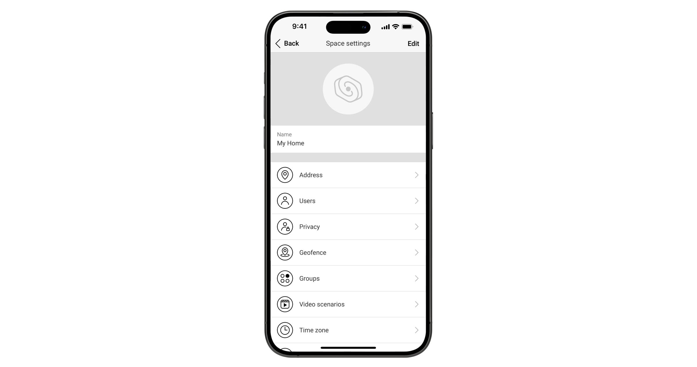
As definições podem ser alteradas na app Ajax:
- Selecione o espaço se tiver vários ou se estiver a utilizar uma app PRO.
- Aceda ao separador Controlo.
- Aceda a Definições tocando no ícone de engrenagem
no canto inferior direito.
- Defina os parâmetros necessários.
- Toque em Voltar para guardar as novas definições.
Funcionalidades adicionais
Videovigilância
Superior Hub Hybrid é compatível com câmaras e NVRs Ajax e com câmaras de terceiros que suportam o protocolo RTSP ou a integração SDK.
É possível calcular o número de câmaras e NVRs que podem ser adicionados ao espaço utilizando o calculador de dispositivos de vídeo.
Cenários
O Superior Hub Hybrid permite criar 32 cenários e minimizar o impacto do fator humano na segurança. O hub pode gerir a segurança de toda a instalação ou grupo de acordo com uma programação; ativar a máquina de fumo se os intrusos entrarem na sala; desenergizar a sala e ligar a iluminação de emergência em caso de incêndio; desligar a água em caso de fuga; controlar dispositivos de iluminação, fechaduras elétricas, persianas e portas de garagem – ao alterar o modo de segurança premindo um botão ou através de um alarme de detetor.
Os cenários podem ser utilizados para reduzir o número de ações de rotina e aumentar a produtividade. Os dispositivos de automação Ajax respondem a alterações na temperatura e na qualidade do ar. Por exemplo, configurar o aquecimento para se ligar a baixas temperaturas, controlar o sistema de abastecimento, o humidificador e o ar condicionado para manter um clima confortável.
Verificação fotográfica
O Superior Hub Hybrid suporta os detetores de movimentos MotionCam e MotionCam Outdoor sem fios. Quando acionados, os detetores tiram uma série de fotografias que podem ser utilizadas para avaliar o desenrolar dos acontecimentos nas instalações ao longo do tempo. Isto alivia os utilizadores de ansiedade e evita que as empresas de segurança enviem patrulhas desnecessárias.
O detetor ativa a câmara quando armado e deteta movimento. Apenas os utilizadores com acesso ao historial de eventos e os funcionários autorizados da empresa de segurança podem ver as verificações visuais de alarme, desde que o sistema de segurança esteja ligado à estação de monitorização.
Se a função Foto por pedido estiver ativada, os detetores podem tirar uma foto ao comando de um utilizador do sistema ou de um utilizador PRO com os direitos adequados. A captura de uma fotografia é sempre registada no historial de eventos do hub.
As fotografias são protegidas por encriptação em todas as fases da transmissão. São armazenadas no servidor Ajax Cloud e não são processadas ou analisadas.
Manutenção
Verifique o funcionamento do Superior Hub Hybrid e dos dispositivos conectados regularmente. A frequência ideal dos controlos é de três em três meses. Limpe a carcaça do dispositivo do pó, teias de aranha e outros contaminantes à medida que vão surgindo. Utilize um pano seco e macio adequado para a manutenção do equipamento.
Não utilize substâncias que contenham álcool, acetona, gasolina e outros solventes ativos para limpar o dispositivo.
Período de suporte definido
Lançamos atualizações de segurança para hubs durante, pelo menos, dois anos do período de garantia.
Especificações técnicas
Garantia
A garantia dos produtos da empresa de responsabilidade limitada “Ajax Systems Manufacturing” é válida durante 2 anos após a compra.
Se o dispositivo não funcionar corretamente, contacte primeiro o Apoio Técnico Ajax. Em maioria dos casos, os problemas técnicos podem ser resolvidos remotamente.
Contactar o Suporte Técnico:
Fabricado por “AS Manufacturing” LLC
