Система Ajax не только защищает от ограбления и пожара, но и предотвращает затопление из-за прорыва трубы или неисправности сантехники. Чтобы внедрить антипотоп-систему, понадобятся датчик протечки воды LeaksProtect, совместимый электроклапан, а также реле WallSwitch или Relay.
Кроме LeaksProtect, можно использовать также датчики сторонних производителей. Их легко подключить к системе Ajax с помощью модулей интеграции Transmitter Jeweller, MultiTransmitter Jeweller и Superior MultiTransmitter Fibra.
Реле Ajax позволяет перекрывать воду не только вручную через приложение, но и автоматически — по тревоге датчика протечки, по расписанию, изменению режима охраны и другим сценариям.
Автоматически перекрывать воду без реле и сторонних электроклапанов можно с Ajax WaterStop. Это умный кран перекрытия воды от Ajax.
WallSwitch и Relay должен устанавливать только квалифицированный электрик, независимо от типа электроцепи, в которой размещено устройство.
Реле размыкают и замыкают электрические цепи. Их можно использовать, чтобы управлять питанием электроустройств.
- Relay — слаботочное реле для дистанционного управления с беспотенциальным «сухим» контактом.
- WallSwitch — силовое реле для дистанционного управления питанием со счетчиком энергопотребления.
Обоими устройствами можно управлять дистанционно через приложение Ajax. Оно позволяет настроить автоматическое замыкание и/или размыкание контактов реле, если меняется состояние охраны, и использование Ночного режима.
Используйте держатель DIN Holder, чтобы установить Relay или WallSwitch на DIN-рейку.
Как выбрать электроклапан для перекрытия воды
Электроклапан открывает и перекрывает воду при получении электрического сигнала. Выбирайте электроклапан с учетом таких параметров:
- Диаметр трубы и тип резьбового соединения фитинга.
- Тип клапана. Есть нормально закрытые и нормально открытые клапаны, а также специальные электроклапаны с двумя устойчивыми состояниями, которые они меняют при подаче импульса постоянного тока.
Преимущественно используются нормально закрытые клапаны. В отличие от нормально открытых клапанов, они перекрывают воду, когда прекращается внешнее питание.
- Напряжение питания. Электроклапаны работают от различного напряжения постоянного и переменного тока: 230 В~, 24 В~, 24 В⎓, 12 В⎓ и др.
- Ручное управление. Поворотный механизм позволяет управлять электроклапаном вручную, как обычным краном. Благодаря этому можно перекрыть воду, даже если телефона нет под рукой.
- Количество входов управления: с одним или двумя входами управления или управляемые изменением полярности электрического питания на входе.
Чтобы внедрить систему перекрытия воды на базе системы Ajax, лучше всего использовать нормально закрытые клапаны с одним входом управления. Чтобы подключить клапаны этого типа, промежуточные реле не нужны. Если использовать импульсные клапаны, приложение Ajax не будет знать состояние клапана: открыт он или закрыт. С Relay используйте электроклапаны, работающие от 12/24 В⎓, с WallSwitch — от 230 В~.
У клапана должно быть два источника питания: основной от электросети объекта и резервный от аккумулятора. В таком случае вы сможете перекрыть воду, даже если в здании пропадет электричество. Резервное питание в 12/24 В⎓ обеспечить легче и дешевле, чем 230 В~.
Принципиальная схема подключения Relay к электромагнитному клапану на 12/24 В⎓
Во время монтажа и эксплуатации придерживайтесь общих правил безопасности при использовании электроприборов, а также требований нормативно-правовых актов по электробезопасности.
В случае потери питания контакты Relay разомкнуты. После восстановления внешнего питания контакты Relay возвращаются в исходное состояние.
Подключение к электроклапану с одним входом управления
Чтобы подключить по схеме, нужно иметь источник внешнего питания на 12/24 В⎓.
Relay и электроклапан можно запитать от одного источника питания. Когда устанавливаете устройство, проследите, чтобы влага не попадала на Relay или места соединения кабелей.
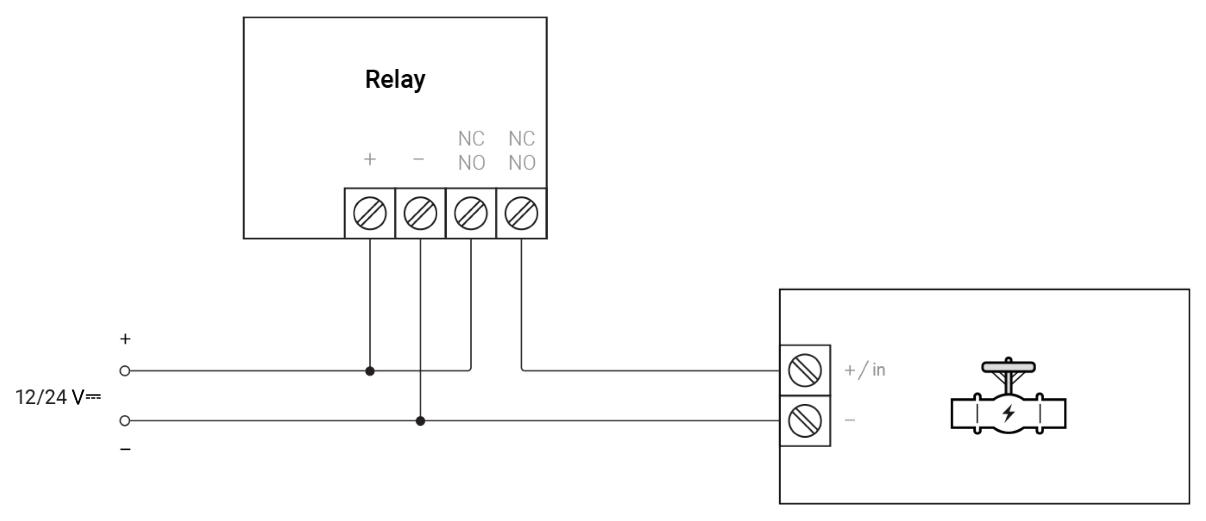
- Подключите источник питания к клеммам питания реле.
- Подключите «+» источника питания к одной из клемм контактов реле, а «+/in» (вход управления) электромагнитного клапана — к другой клемме контактов реле.
- Подключите контакт «—» электромагнитного клапана к «—» источника питания.
При таком подключении Relay будет управлять перекрытием электромагнитного клапана.
Примеры клапанов:
- PIE T20-S2-B
- CONVA A20-T25-S2-C
- Ebowan 12 V DC
Управление электромагнитным клапаном 12/24 В⎓ с одним входом управления
Настройка Relay
- Перейдите на вкладку Устройства
.
- Зайдите в меню Relay.
- Перейдите в Настройки
.
- Выберите Бистабильный режим работы.
- Задайте Состояние контакта — Нормально открыт.
Управление электроклапаном в приложении Ajax
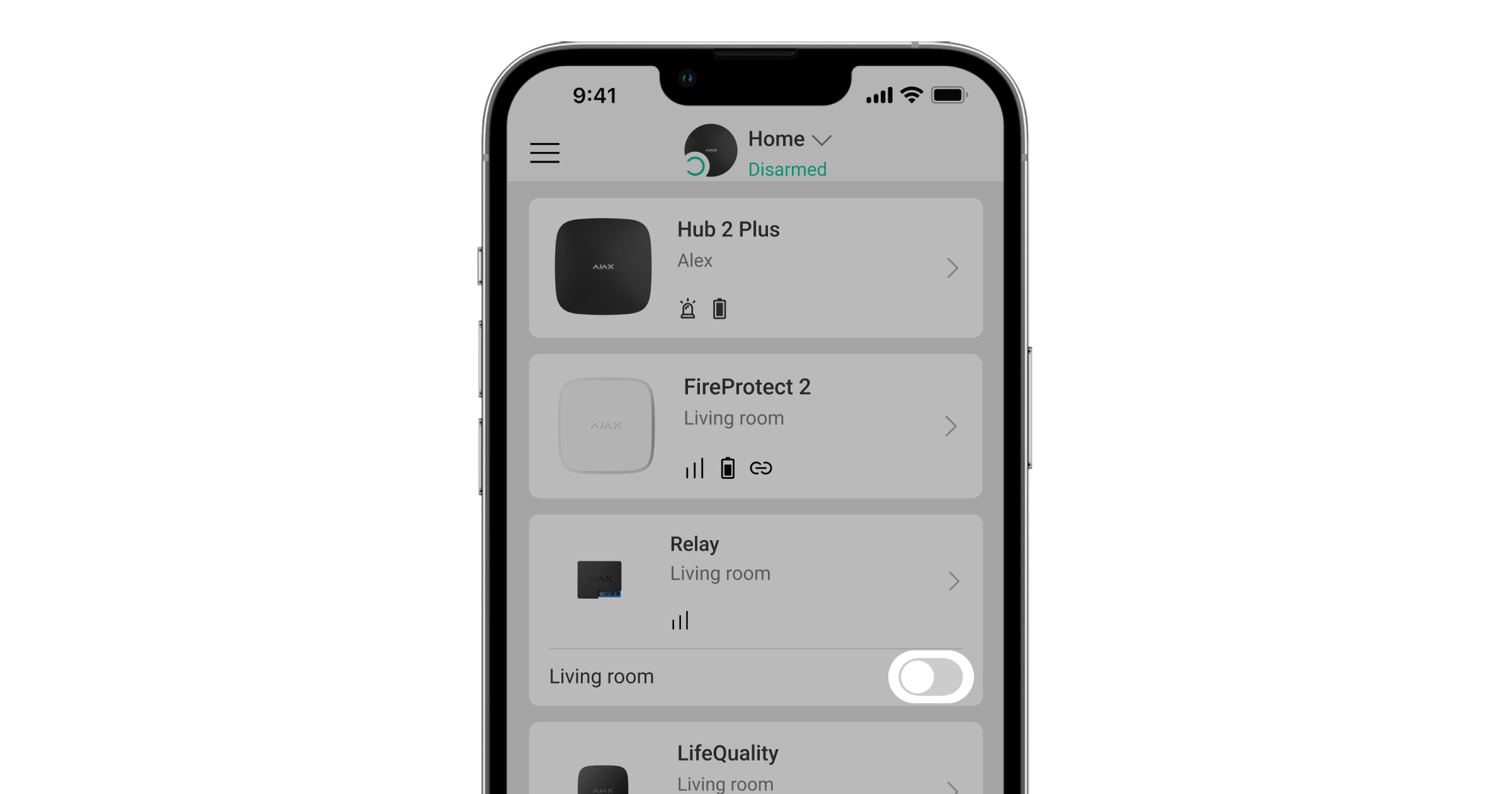
Нажмите на переключатель в строке Relay — состояние контактов реле изменится на противоположное.
Когда контакты Relay замыкаются, на электроклапан подается питание, и он открывается. Когда контакты размыкаются, подача питания на электроклапан прекращается, и вода перекрывается.
Подключение к электроклапану с двумя входами управления
Чтобы подключить по схеме, необходимо иметь источник внешнего питания на 12/24 В⎓ и промежуточное реле типа SPDT на 12/24 В⎓.
Relay, промежуточное реле и электроклапан можно запитать от одного источника питания. Когда устанавливаете устройство, проследите, чтобы влага не попадала на Relay, промежуточное реле или места соединения кабелей.
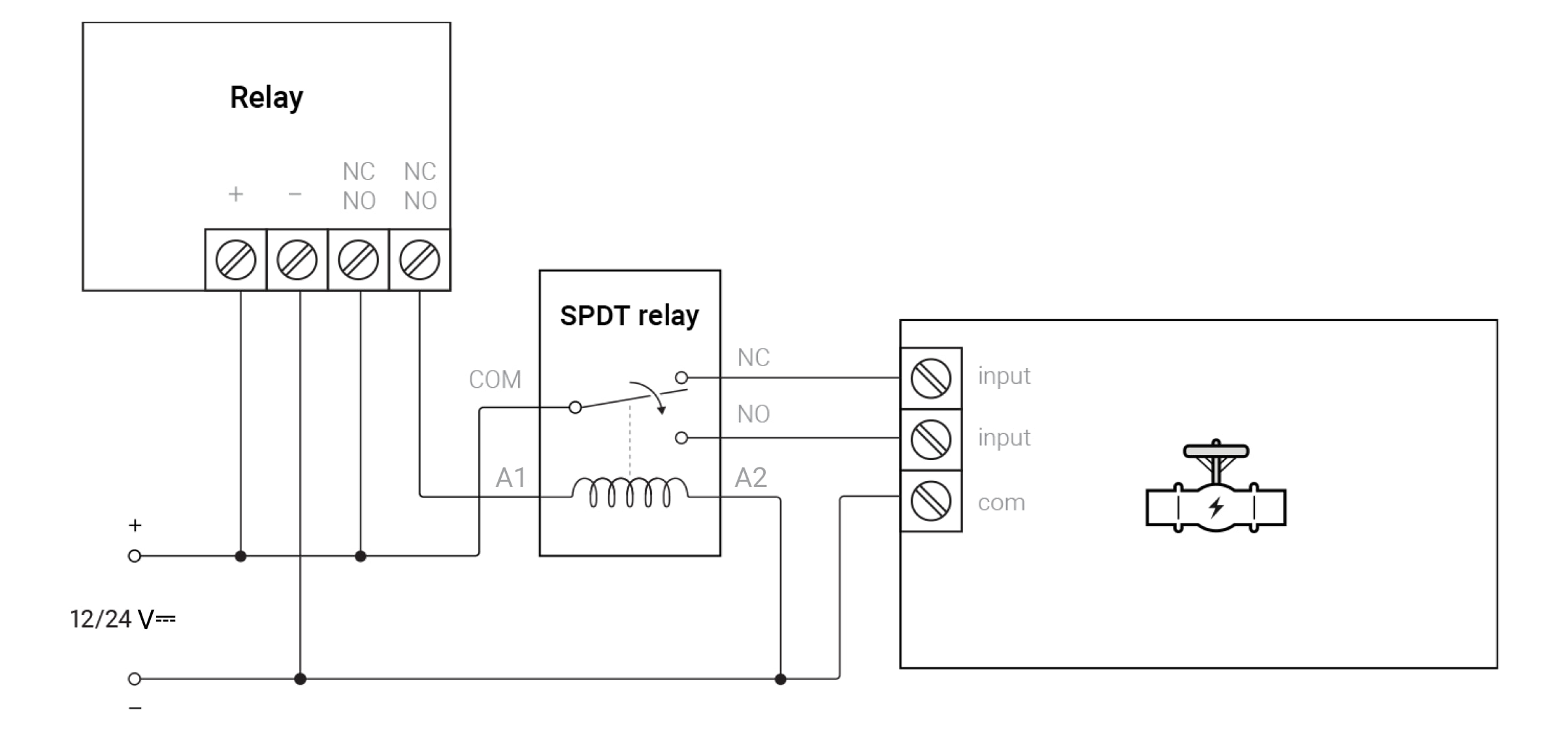
- Подключите источник питания к клеммам питания Relay.
- Подключите «+» источника питания к одной из клемм контактов Relay, а клемму A1 промежуточного реле — к другой клемме контактов Relay.
- Подключите контакт com электромагнитного клапана (общий контакт) и контакт A2 промежуточного реле к «—» источника питания.
- Подсоедините клемму COM промежуточного реле к «+» источника питания.
- Подключите клемму NC промежуточного реле к управляющему входу открытия электроклапана, а клемму NO — к входу закрытия.
При таком подключении Relay будет управлять перекрытием электромагнитного клапана.
Управление электромагнитным клапаном 12/24 В⎓ с двумя входами управления
Настройка Relay
- Перейдите на вкладку Устройства
.
- Зайдите в меню Relay.
- Перейдите в Настройки
.
- Выберите Бистабильный режим работы.
- Задайте Состояние контакта — Нормально закрыт.
Управление электроклапаном в приложении Ajax
Нажмите на переключатель в строке Relay — состояние контактов реле изменится на противоположное.
При замыкании контактов клапан закрывается, при размыкании — открывается.
Подключение к электроклапану с входом управления “смена полярности”
Чтобы подключить по схеме, необходимо иметь источник внешнего питания на 12/24 В⎓ и промежуточное реле типа DPDT на 12/24 В⎓.
Relay, промежуточное реле и электроклапан можно питать от одного источника. При установке не допускайте попадания влаги на Relay, промежуточное реле или на места соединения кабелей.
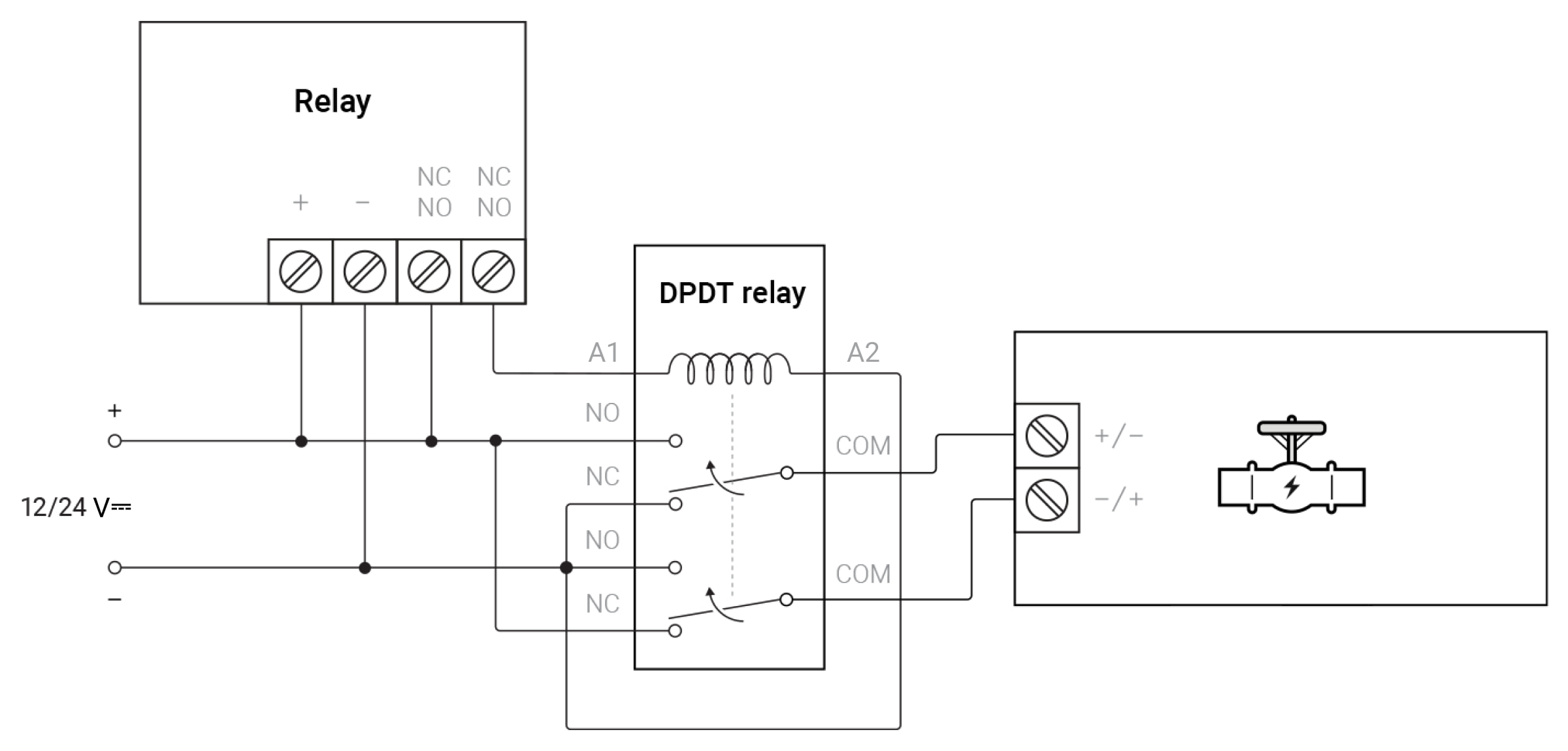
- Подключите источник питания к клеммам питания Relay.
- Подключите «+» источника питания к одной из клемм контактов Relay, а клемму A1 промежуточного реле — к другой клемме контактов Relay.
- Подключите клемму NO первой группы контактов реле к клемме «+«, а клемму NC — к «—» источника питания.
- Подключите клемму NO второй группы контактов реле к клемме «—«, а клемму NC — к «+» источника питания.
- Подключите клемму COM первой группы контактов промежуточного реле к первому входу управления, а клемму «COM» второй группы контактов реле — ко второму входу управления электроклапана.
- Подключите контакт A2 промежуточного реле к «—» источника питания.
При такой схеме подключения Relay будет управлять промежуточным реле, которое подает на входы управления электроклапана напряжение различной полярности. Полярность входного напряжения определяет состояние электроклапана: открыт или закрыт.
Примеры клапанов:
- CONVA A20-T15-S2-C
- CVX-15N
Управление электромагнитным клапаном 12/24 В⎓ с управлением сменой полярности
Настройка Relay
- Перейдите на вкладку Устройства
.
- Зайдите в меню Relay.
- Перейдите в Настройки
.
- Выберите Бистабильный режим работы.
- Задайте Состояние контакта — Нормально закрыт.
Управление электроклапаном в приложении Ajax
Нажмите на переключатель в строке Relay — состояние контактов реле изменится на противоположное.
При замыкании контактов клапан закрывается, при размыкании — открывается.
Принципиальная схема подключения WallSwitch к электромагнитному клапану на 230 В~
Во время монтажа и эксплуатации придерживайтесь общих правил безопасности при использовании электроприборов, а также требований нормативно-правовых актов по электробезопасности.
Подключение к электроклапану 230 В~ с одним входом управления
Для подключения по схеме необходимо иметь источник внешнего питания 230 В~.
WallSwitch и электроклапан можно запитать от одного источника питания. При установке не допускайте попадания влаги на WallSwitch или на места соединения кабелей.
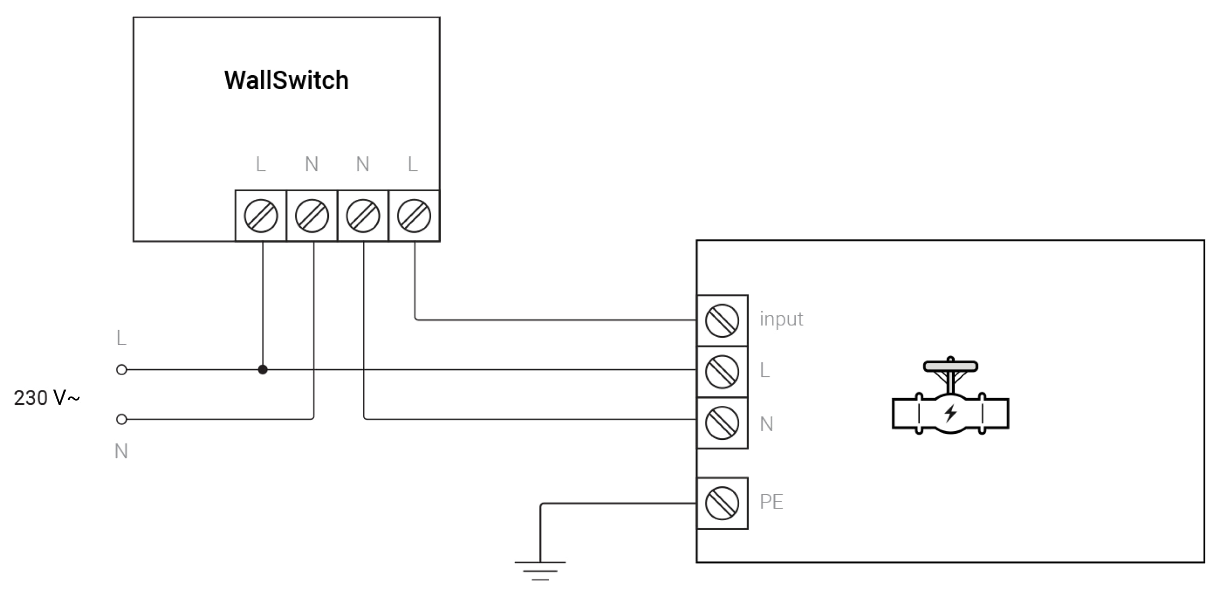
- Подключите источник питания к клеммам питания WallSwitch, учитывайте полярность.
- Подсоедините выходную клемму N (нейтраль питания) WallSwitch к клемме N электроклапана.
- Подключите выходную клемму L (фаза питания) WallSwitch к входу управления электроклапана.
- Подключите клемму L электроклапана к фазе 230 В~ источника питания.
- Заземлите контакт PE электроклапана.
При таком подключении WallSwitch будет управлять перекрытием электромагнитного клапана. При замыкании контактов WallSwitch клапан закрывается. При размыкании — открывается.
В некоторых клапанах можно выбирать нормальное состояние: открытый или закрытый при замкнутом входе управления (input).
Примеры клапанов:
- ESBE MBA 100 series
- 2W-160-15C
Управление электромагнитными клапанами 230 В~ с одним входом управления
Дополнительной настройки WallSwitch через приложение не требуется.
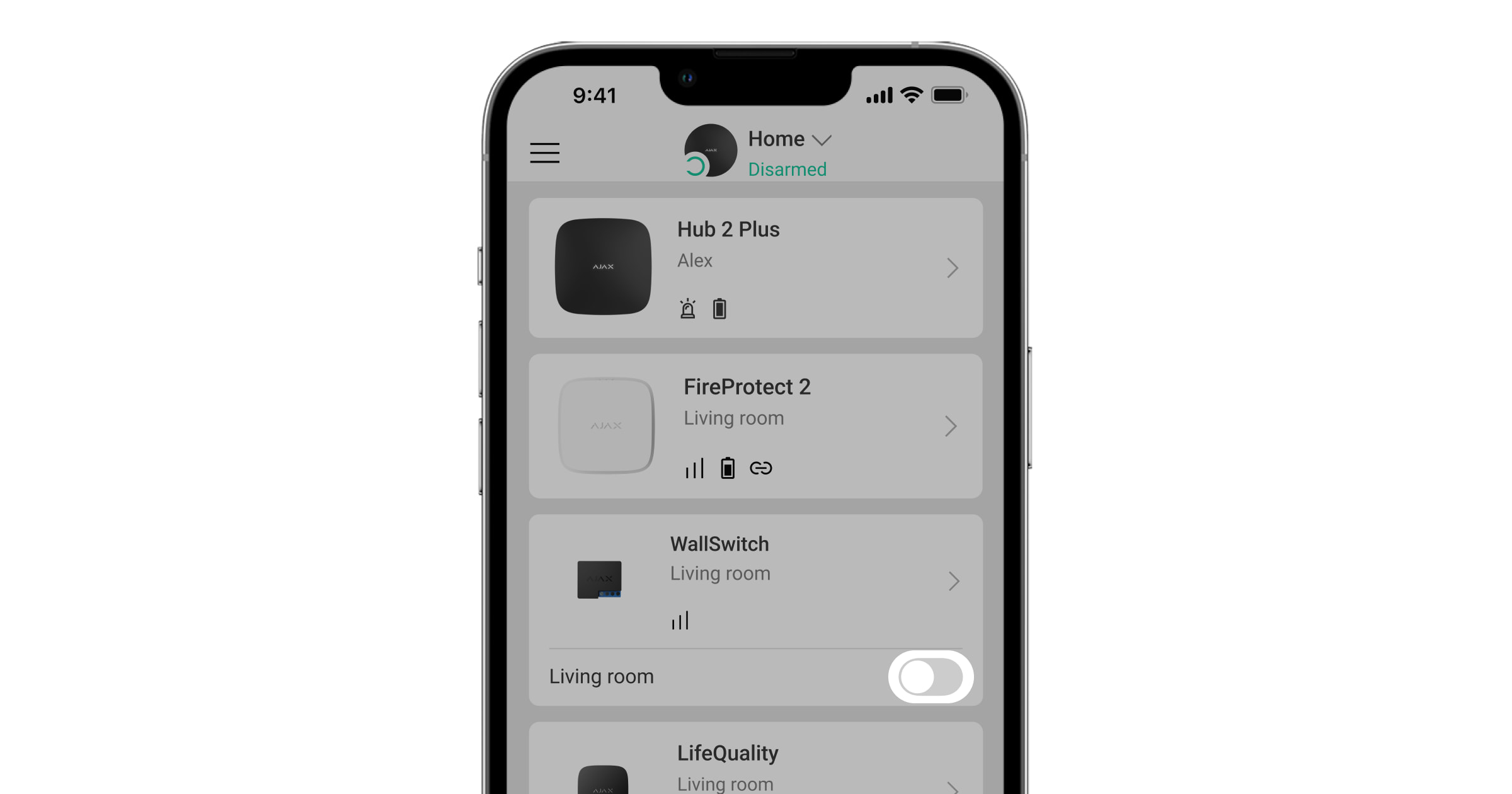
Нажмите на переключатель в строке WallSwitch — состояние контактов реле изменится на противоположное.
Когда контакты WallSwitch замыкаются, на электроклапан подается питание, и он закрывается. Когда контакты размыкаются, подача питания на вход управления прекращается, а электроклапан открывается.
Подключение к электроклапану 230 В~ с двумя входами управления
Для подключения по схеме необходимо иметь источник внешнего питания 230 В~ и промежуточное реле типа SPDT на 230 В~.
WallSwitch, промежуточное реле и электроклапан можно запитать от одного источника питания. При установке не допускайте попадания влаги на WallSwitch, промежуточное реле или на места соединения кабелей.
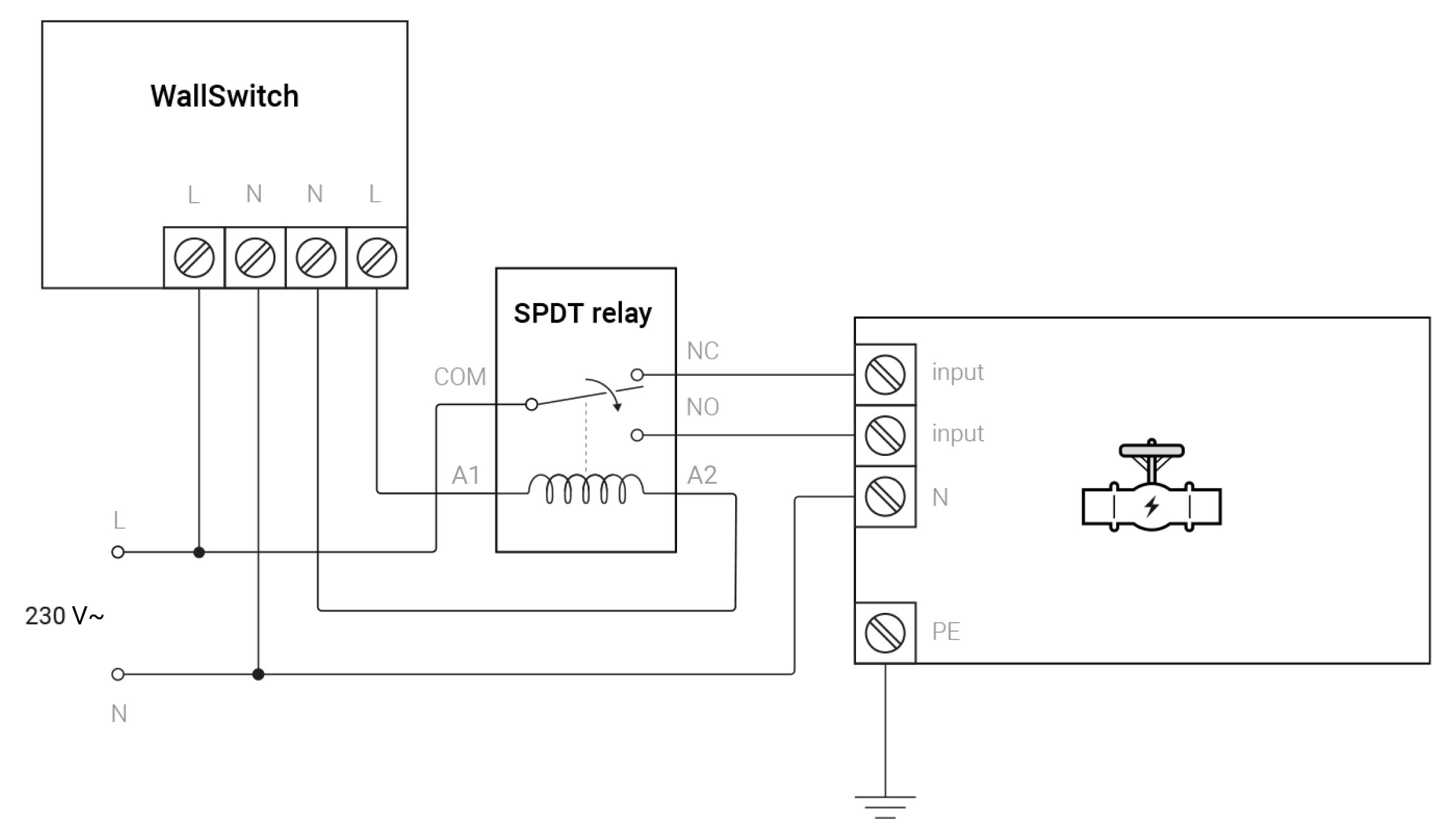
- Подключите источник питания к клеммам питания WallSwitch, учитывайте полярность.
- Подключите выходную клемму N (нейтраль питания) WallSwitch к клемме A2 промежуточного реле.
- Подключите выходную клемму L (фаза питания) WallSwitch к клемме A1 промежуточного реле.
- Подключите клемму COM промежуточного реле к L источника питания.
- Подключите клемму NC промежуточного реле к входу управления открытием электроклапана, а клемму NO — к входу управления закрытием.
- Подключите клемму N (нейтраль питания) электроклапана к N источнику питания и заземлите контакт PE электроклапана.
При таком подключении WallSwitch будет управлять перекрытием электромагнитного клапана.
Управление электромагнитными клапанами 230 В~ с двумя входами управления
Дополнительной настройки WallSwitch через приложение не требуется.
Нажмите на переключатель в строке WallSwitch — состояние контактов реле изменится на противоположное.
Когда контакты WallSwitch замыкаются, на электроклапан подается питание, и он закрывается. Когда контакты размыкаются, подача питания на вход управления прекращается, а электроклапан открывается.
Автоматическое управления электроклапаном
Чтобы управлять одним или несколькими электроклапанами при постановке/снятии системы безопасности с охраны, по тревоге или при других условиях, создайте сценарий. Сценарий по тревоге датчика протечки позволяет создать антипотоп-систему, которая будет перекрывать воду без пользователя.
Сценарий можно создать в настройках реле:
Устройства → Relay (или WallSwitch) → Настройки
→ Сценарии.
Быстрый доступ к устройствам автоматизации
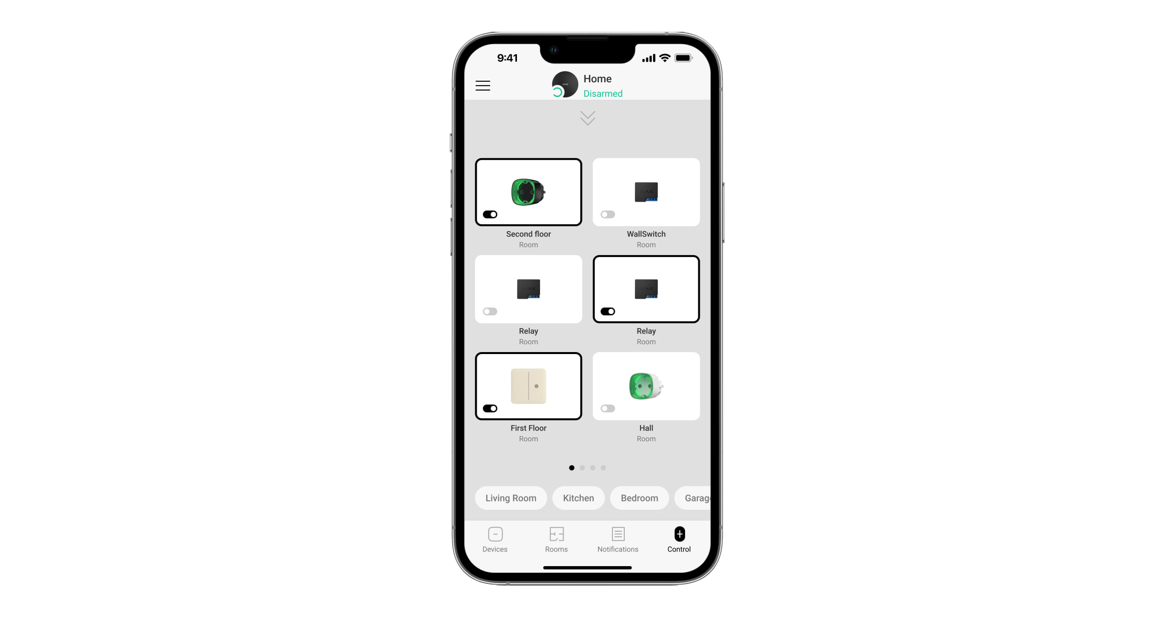
Для быстрого доступа к управлению Relay, WallSwitch и другими устройствами автоматизации выполните следующие шаги в приложениях Ajax:
- Перейдите на вкладку Управление.
- Сделайте свайп вверх.
- Управляйте нужными устройствами.
- Сделайте свайп вниз, чтобы вернуться к вкладке Управление.
