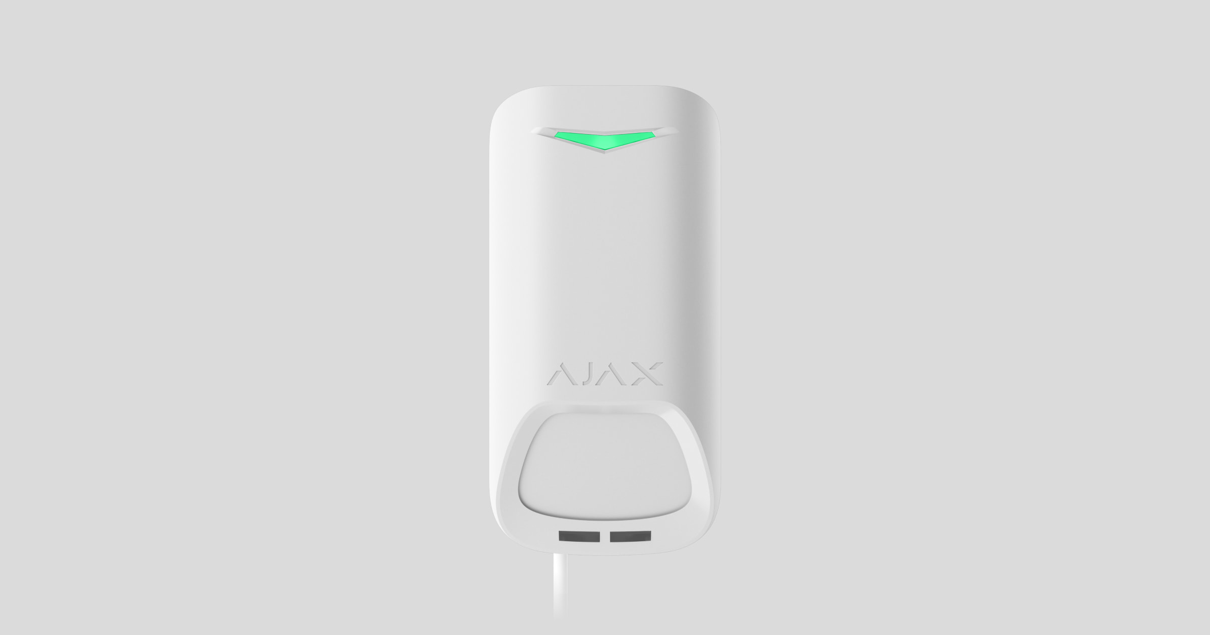
Superior MotionProtect G3 Fibra is een bekabelde bewegingsdetector. Het detecteert beweging op een afstand tot 49 ft. Naast het gebruik van de IR-sensor, past de detector een extra radiofrequentiescan toe met een K-band microgolfsensor die infraroodverstoringen filtert. Bovendien beschikt het over een anti-maskeringssysteem dat pogingen detecteert om het gezichtsveld van de detector te blokkeren. Het apparaat is uitsluitend ontworpen voor gebruik binnenshuis en voldoet aan de vereisten van EN 50131 (Grade 3).
Superior MotionProtect G3 Fibra is compatibel met Hub Hybrid (2G) en Hub Hybrid (4G). Verbinding met andere hubs, radiosignaalversterkers, ocBridge Plus, en uartBridge is niet mogelijk.
De detector wisselt gegevens uit met de hub via het beveiligde en bekabelde Fibra-communicatieprotocol. Bij gebruik van een U/UTP-getwist paar cat.5-kabel kan de bekabelde communicatie maximaal 6,550 ft overbruggen.
Superior MotionProtect G3 Fibra maakt deel uit van de bekabelde apparaten uit de Superior-productlijn. Alleen geaccrediteerde Ajax Systems-partners mogen de Fibra-producten aanschaffen, installeren en beheren.
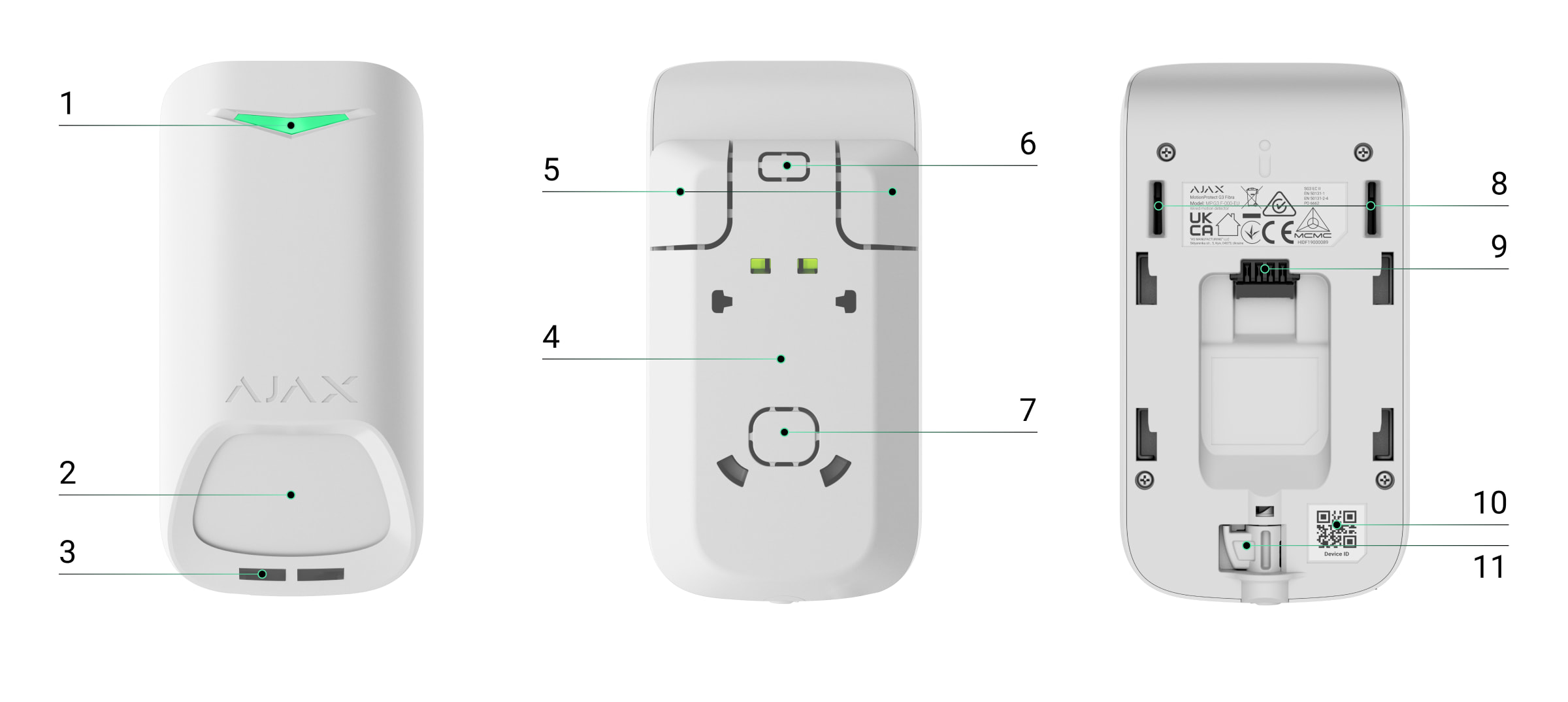
Functionele elementen
- Led-indicator.
- Gevoelig gebied van de IR-bewegingssensor van de detector.
- Maskeringssensor.
- SmartBracket-montagepaneel Schuif het paneel naar beneden om het te verwijderen.
- Geperforeerde delen van het montagepaneel. Activeert een sabotagebeveiliging bij pogingen om het apparaat van het oppervlak los te maken. Breek ze niet af.
- Geperforeerd deel van het montagepaneel om kabels vanaf de bovenkant van het apparaat door te voeren.
- Geperforeerd deel van het montagepaneel om kabels door de muur te leiden.
- Sabotagebeveiliging.
- Aansluiting voor klemmenstrook.
- QR-code met het apparaat-ID. Deze wordt gebruikt om het apparaat toe te voegen aan de hub.
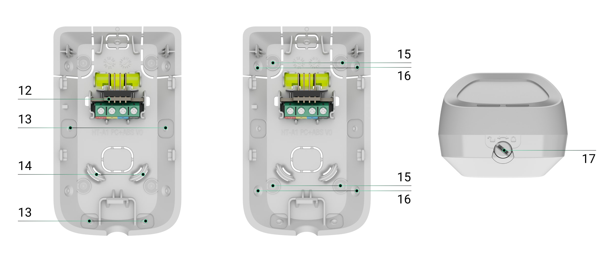
- Vergrendeling met sabotagebeveiliging op het slot voor SmartBracket.
- Klemmenstrook om het apparaat aan te sluiten.
- Uitsparingen voor het boren van gaten om kabels langs de zij- of onderkant van het apparaat te leiden.
- Bevestigingsmiddelen om de kabels met kabelbinders vast te zetten.
- Plekken voor het boren van gaten om het apparaat op het oppervlak te monteren.
- Plekken voor het boren van gaten om het apparaat op de bevestiging te monteren.
- Slot voor SmartBracket. Hiermee bevestigt u het apparaat op het SmartBracket-montagepaneel.
Werkingsprincipe
Superior MotionProtect G3 Fibra is een bekabelde IR-bewegingsdetector met extra K-Band microgolfsensor en anti-maskeringssysteem. Het kan inbraak identificeren door bewegende objecten te detecteren met temperaturen die dicht bij de temperatuur van het menselijk lichaam liggen.
Wanneer een ingeschakelde detector beweging detecteert, voert het een extra RF-scan uit om valse alarmen door IR-verstoringen te voorkomen, zoals luchtstromen, verwarmde gordijnen en jaloezieën, ventilatoren, open haarden, airconditioners en andere waarschijnlijke bronnen van valse alarmen.
In geval van een alarm stuurt het meteen een alarm naar de hub. Hierdoor worden de sirenes die op het systeem zijn aangesloten geactiveerd, de scenario’s geactiveerd en gebruikers en het beveiligingsbedrijf op de hoogte worden gebracht. Alle alarmen en gebeurtenissen van Superior MotionProtect G3 Fibra worden opgenomen in het logboek van de Ajax-apps.
Gebruikers en het bewakingsbedrijf weten precies waar beweging is gedetecteerd. De meldingen bevatten de naam van een space (de naam van de bewaakte locatie), de naam van het apparaat, en de virtuele ruimte waaraan het apparaat is toegewezen.
De detector schakelt niet meteen naar de ingeschakelde modus. De tijd voor het overschakelen is afhankelijk de vertraging bij vertrek (gespecificeerd in de instellingen van het apparaat) en het polling-interval tussen de hub en detector. De polling-interval kan worden ingesteld in de Jeweller/Fibra-instellingen, standaard is dit 36 seconden. In het eerste geval wordt de vertraging ingesteld door een gebruiker of een PRO met beheerdersrechten. In het tweede geval treedt de vertraging op omdat de hub één polling-interval nodig heeft om de detector op de hoogte te stellen van de wijziging van de beveiligingsmodus.
Bescherming tegen valse alarmen
Superior MotionProtect G3 Fibra gebruikt het SmartDetect-algoritme om valse alarmen te voorkomen. Met dit algoritme kan de detector het thermische diagram analyseren dat door de sensor wordt gelezen: de intensiteit van de infrarode straling, de grootte van de warmtevlek, de tijd die in het detectiegebied wordt doorgebracht en andere parameters.
Na deze fase wordt een extra RF-scan van de ruimte uitgevoerd met de ingebouwde K-band microgolfsensor. Afhankelijk van het resultaat wordt het alarm wel of niet geactiveerd.
Temperatuurcompensatie
Dankzij de temperatuurcompensatie reageert de detector op bewegingen, zelfs als de temperatuur op locatie dicht bij die van het menselijk lichaam ligt. In dit artikel leest u meer over temperatuurcompensatie.
Anti-maskeringssysteem
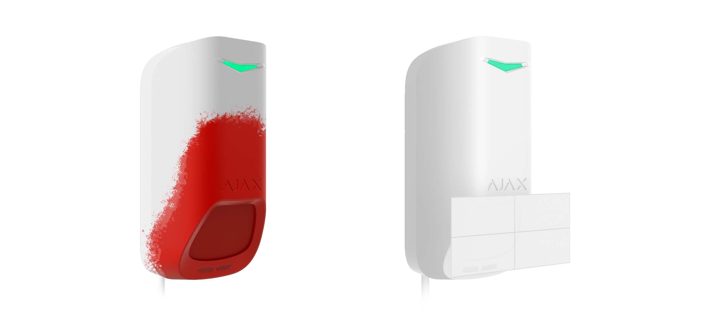
Maskeren is een poging om het zicht van de detector te blokkeren. Superior MotionProtect G3 Fibra detecteert de volgende soorten van maskering:
- Een obstakel voor de detectiezone van de sensor van detector.
- Schilderen over de bewegingsgevoelige sensor van de detector.
- Het afplakken van de bewegingsgevoelige sensor van de detector.
Het systeem informeert gebruikers en de meldkamer van een beveiligingsbedrijf over het maskeren. De maximale detectietijd voor maskering is maximaal 120 s (afhankelijk van het type obstakel en de afstand tot het obstakel).
Als de functie Anti-maskering is ingeschakeld, is deze altijd actief en werkt deze ongeacht de beveiligingsmodus.
Fibra-protocol voor gegevensoverdracht
Het apparaat gebruikt Fibra-technologie om alarmen en gebeurtenissen te verzenden en om de firmware bij te werken. Dit bekabelde protocol voor gegevensoverdracht zorgt voor een snelle en betrouwbare tweerichtingscommunicatie tussen de hub en de verbonden apparaten.
Firmware-update
Als er een nieuwe firmwareversie voor Superior MotionProtect G3 Fibra beschikbaar is, verschijnt het pictogram in Ajax-apps op het tabblad Apparaten
. Een beheerder of een PRO met toegang tot de systeeminstellingen kan een update uitvoeren in de statussen of instellingen van het apparaat. De instructies op het scherm helpen u om de firmware succesvol bij te werken.
Gebeurtenissen naar de meldkamer verzenden
Het Ajax-systeem kan alarmmeldingen niet alleen naar de PRO Desktop-bewakingsapp versturen, maar ook naar de meldkamer in bestandsformaten van SurGard (Contact ID), SIA (DC-09), ADEMCO 685 en andere protocollen.
Superior MotionProtect G3 Fibra kan de volgende gebeurtenissen verzenden:
- Bewegingsalarm.
- Maskeringsalarm.
- Storing/herstel van de IR-sensor.
- Storing/herstel van de K-band microgolfsensor.
- Storing/herstel van de magnetische maskeringssensor.
- Sabotage-alarm/herstel. Herstel van sabotagebeveiliging.
- Lage voedingsspanning en het terugkeren naar normale spanningswaarden.
- Verlies en herstel van verbinding met de hub.
- Permanente deactivering en activering van het apparaat.
- Eenmalige deactivering en activering van het apparaat.
Wanneer een alarmmelding wordt ontvangen, weet de operator van de meldkamer van het beveiligingsbedrijf wat er is gebeurd en waar het responsteam precies naartoe moet worden gestuurd. Dankzij de adresseerbaarheid van de Ajax-apparaten kunnen gebeurtenissen verzonden worden naar PRO Desktop of de meldkamer met informatie over het type apparaat, de naam, beveiligingsgroep, en virtuele ruimte. De lijst van verzonden parameters kan variëren, afhankelijk van de meldkamer en het geselecteerde communicatieprotocol.
U vindt het ID-nummer van het apparaat, het lusnummer (zone), en het lijnnummer bij de Statussen van het apparaat.
Selectie van de installatieplaats
Bij de keuze waar u Superior MotionProtect G3 Fibra wilt installeren, moet u rekening houden met de parameters die de werking beïnvloeden:
- Fibra-signaalsterktetest.
- De lengte van de kabel voor het aansluiten van de detector.
- Detectiezone.
- De afstand tussen de detector en een andere detector met een K-band microgolfsensor moet 8 inch of meer bedragen.
Denk aan de aanbevelingen voor plaatsing bij het ontwikkelen van een project voor het systeem van de faciliteit. Het Ajax-systeem moet ontworpen en geïnstalleerd worden door specialisten. Een lijst met erkende Ajax-partners is hier beschikbaar.
Fibra-signaalsterkte
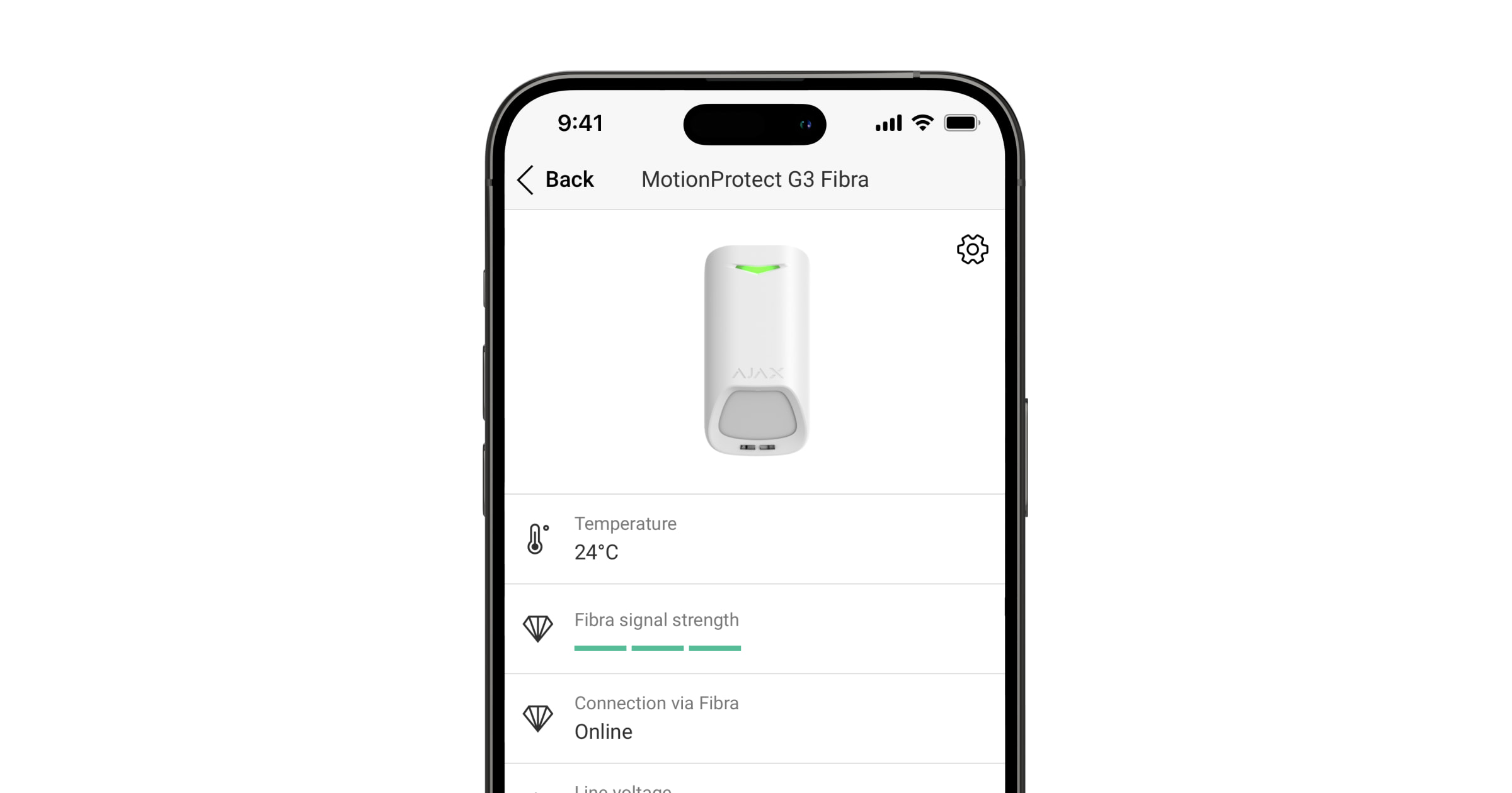
De Fibra-signaalsterkte is de verhouding tussen de datapakketten die in een bepaalde periode afgeleverd had moeten worden en het aantal niet-afgeleverde of beschadigde pakketten. U kunt de signaalsterkte aflezen op het pictogram in het tabblad Apparaten
in de Ajax-apps:
- Drie streepjes — uitstekende signaalsterkte.
- Twee streepjes — goede signaalsterkte.
- Eén streepje — lage signaalsterkte, een stabiele werking wordt niet gegarandeerd.
- Doorgestreept pictogram — geen signaal, een stabiele werking is niet gegarandeerd.
Voedingstest bussen
De test simuleert het maximale energieverbruik van apparaten die op de hub zijn aangesloten. Als het systeem de test doorstaat, dan hebben alle apparaten in elke situatie altijd voldoende stroom. Na de test geeft de app een melding weer met de status van elke bus:
- Test geslaagd.
- Test geslaagd met storingen.
- Test mislukt.
Detectiegebied van de bewegingsdetector
De locatie van de detector bepaalt het gebied dat moet worden bewaakt en de effectiviteit van het beveiligingssysteem. Houd bij het kiezen van de installatieplaats rekening met de richting van de sensoren van de detector, de kijkhoeken en de aanwezigheid van obstakels in het beeld van de detector.
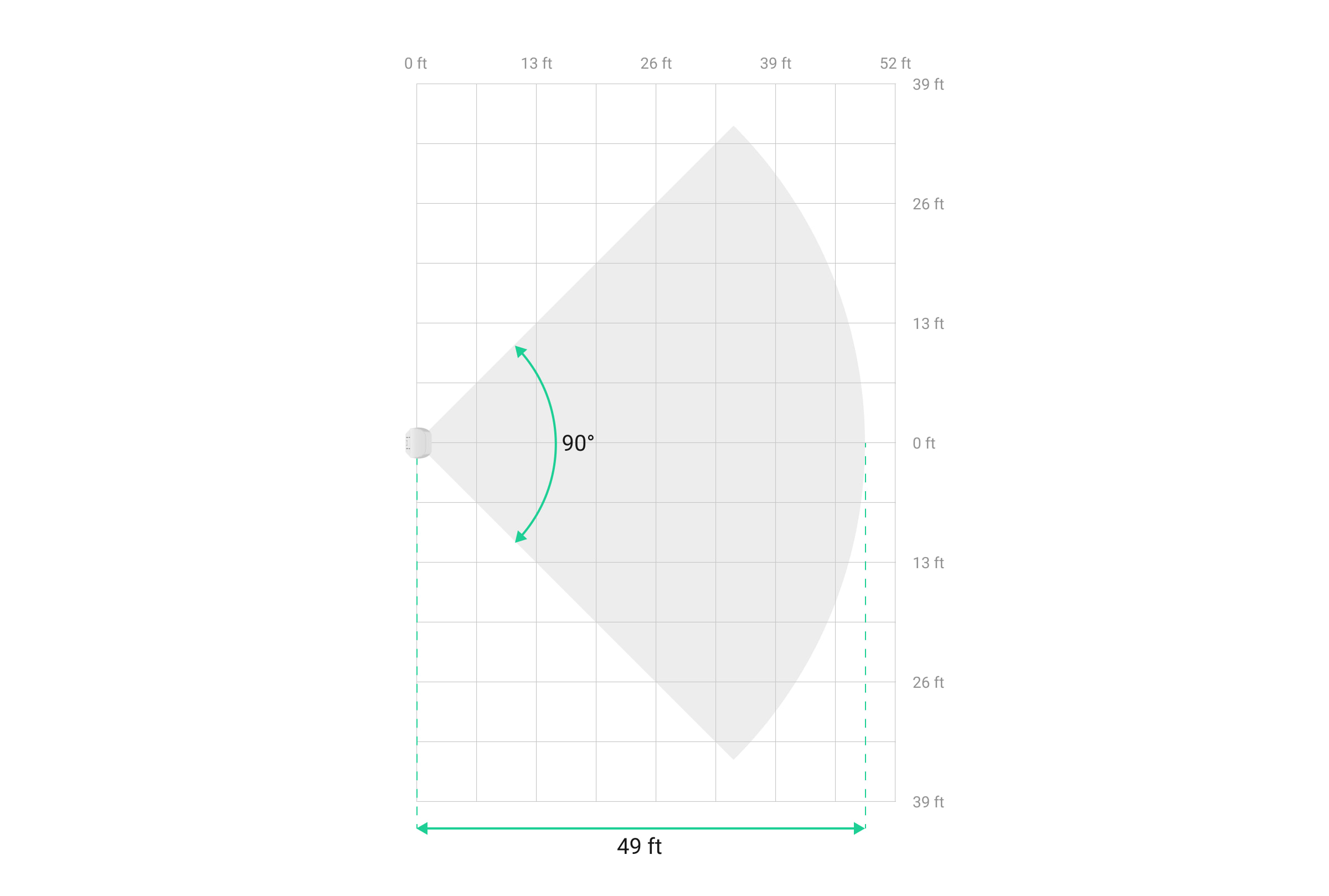
De detector kan beweging detecteren tot op een afstand van 49 ft. De richting van de sensor van de detector moet loodrecht staan op het beoogde pad van binnenkomst in het gebouw. Zorg dat meubels, kamerplanten, vazen, decoratieve elementen of glazen elementen het gezichtsveld van de detector niet belemmeren.
Horizontale kenmerken van de detectiezone
Verticale kenmerken van de detectiezone
Voer bij het installeren van de detector de Detectiezonetest uit. Hiermee kunt u het functioneren van het apparaat controleren en nauwkeurig bepalen in welke sector de detector reageert op beweging.
Installeer de detector niet
- Buitenshuis. Dit kan leiden tot schade aan het apparaat.
- Op plaatsen waar objecten en structuren het zicht van de detector kunnen blokkeren. Bijvoorbeeld achter een bloem of een zuil.
- Op plaatsen waar glazen constructies het zicht van de detector kunnen belemmeren. De detector detecteert geen beweging achter glas.
- In gebouwen met een temperatuur en luchtvochtigheid buiten de toegestane grenzen. Dit kan leiden tot schade aan het apparaat.
- In de buurt van andere detectoren met K-band microgolfsensoren. De minimale afstand tussen apparaten moet minimaal 8 inch bedragen. Anders kan het de detectiekwaliteit verminderen of een vals alarm veroorzaken door verstoring van de K-band microgolfsensoren.
- Op plaatsen met een lage of instabiele Fibra-signaalsterkte.
Ontwerp en voorbereiding
Het is van cruciaal belang dat het systeemproject goed ontworpen wordt zodat de apparaten correct geïnstalleerd en geconfigureerd worden. Bij het ontwerp moet rekening worden gehouden hoeveel en welke apparaten zich in het object bevinden, hun exacte locatie, op welke hoogte ze precies worden geplaatst, de lengte van de bekabelde Fibra-bussen, het gebruikte kabeltype, en andere factoren.
Superior MotionProtect G3 Fibra kan op elk punt van de Fibra-kabel worden aangesloten. Bij gebruik van een U/UTP-getwist paar cat.5-kabel kan de bekabelde communicatie maximaal 6,550 ft overbruggen.
Ajax-systemen ondersteunen ook Bus– en Ringtopologieën.
Het type en de lengte van de kabels
Aanbevolen kabeltypen voor het aansluiten van Superior MotionProtect G3 Fibra op de hub:
- U/UTP cat. 5, 4 × 2 × 0,51 (24 AWG), kopergeleider.
- Signaalkabel 4 × 0,22 mm², kopergeleider.
Het bereik van de bekabelde verbinding kan variëren als u een ander soort kabel gebruikt. Andere soorten kabels zijn niet getest.
Verificatie met een calculator
Gebruik de Fibra-voedingscalculator om er zeker van te zijn dat het project correct ontworpen is en dat het systeem zal werken in de praktijk. Dit helpt om de communicatiekwaliteit en de kabellengte voor de bekabelde Fibra-apparaten te controleren bij het ontwerpen van het systeemproject.
De installatie voorbereiden
Kabelmanagement
Als u kabels gaat leggen, raadpleeg dan de elektrische en brandveiligheidsvoorschriften in uw regio. Volg deze normen en voorschriften zorgvuldig op. Tips voor de plaatsing van de kabels zijn in dit artikel te lezen.
Kabels leggen
We raden aan dat u het stuk Selectie van de installatieplaats goed doorleest voordat u iets gaat installeren. Wijk niet af van het systeemproject. Als u de basisinstallatievoorschriften en de aanbevelingen van deze handleiding niet naleeft, kan dit ertoe leiden dat Superior MotionProtect G3 Fibra niet correct functioneert en dat de verbinding verloren gaat. Tips voor het leggen van de kabels zijn in dit artikel te lezen.
Kabels voorbereiden op de aansluiting
Verwijder de isolatielaag en strip de kabel met een speciale kabelstripper. De uiteinden van de kabels die in de klemmen van het apparaat worden gestoken, moeten worden vertind of voorzien van een krimpkous. Dit zorgt voor een betrouwbare aansluiting en beschermt de geleider tegen oxidatie. Tips voor de voorbereiden van de kabels zijn in dit artikel te lezen.
Installatie en verbinding
Controleer voordat u Superior MotionProtect G3 Fibra installeert of de beste locatie voor de detector is geselecteerd en voldoet aan de vereisten van deze handleiding. Kabels moeten aan het zicht worden onttrokken en op een moeilijk bereikbare plaats worden gelegd om de kans op sabotage te verkleinen. In het ideale geval monteert u deze in de muren, de vloer, of het plafond. Voer vóór de definitieve installatie de Detectiezonetest en Fibra-signaalsterktetest uit.
Om een detector te monteren:
- Zet in de Ajax PRO-app de voeding van de lijnen uit:
- Hub → Instellingen
→ Bussen → Voeding bussen
- Hub → Instellingen
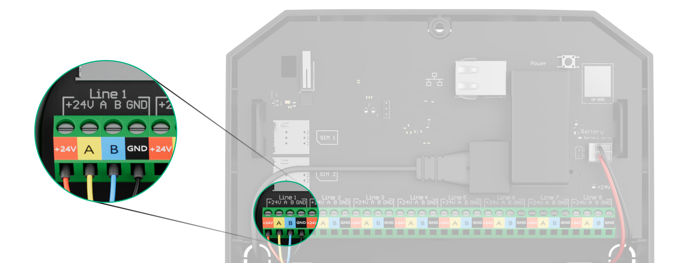
- Leid de kabel om Superior MotionProtect G3 Fibra aan te sluiten op de behuizing van de hub. Verbind de kabels met de juiste kabel van de hub.
+24V — 24 V⎓ voedingsaansluiting.
А, B — signaalaansluitingen.
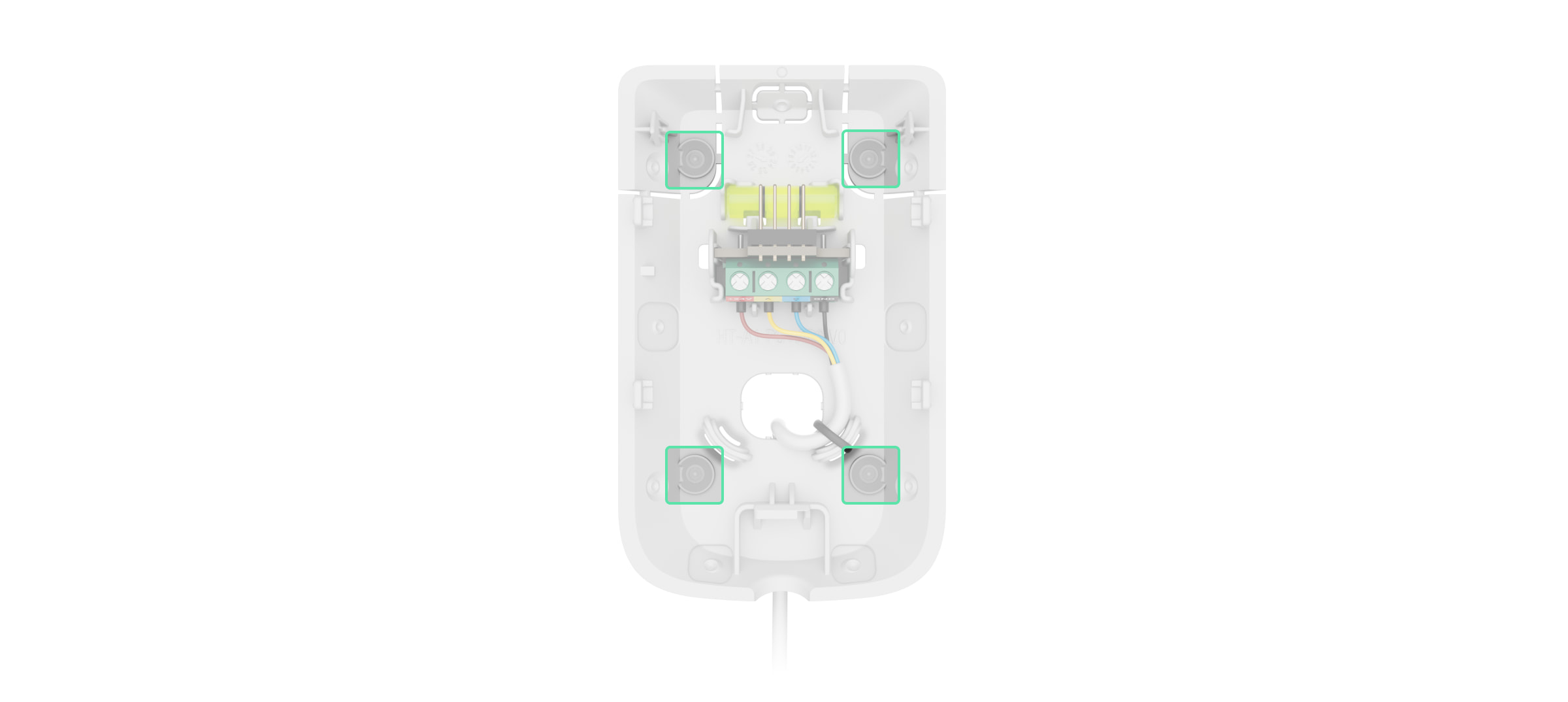
GND — aarde. - Verwijder het SmartBracket-montagepaneel van de detector. Breek voorzichtig het corresponderende geperforeerde deel eruit om de kabel aan de achter- of bovenkant uit te voeren.
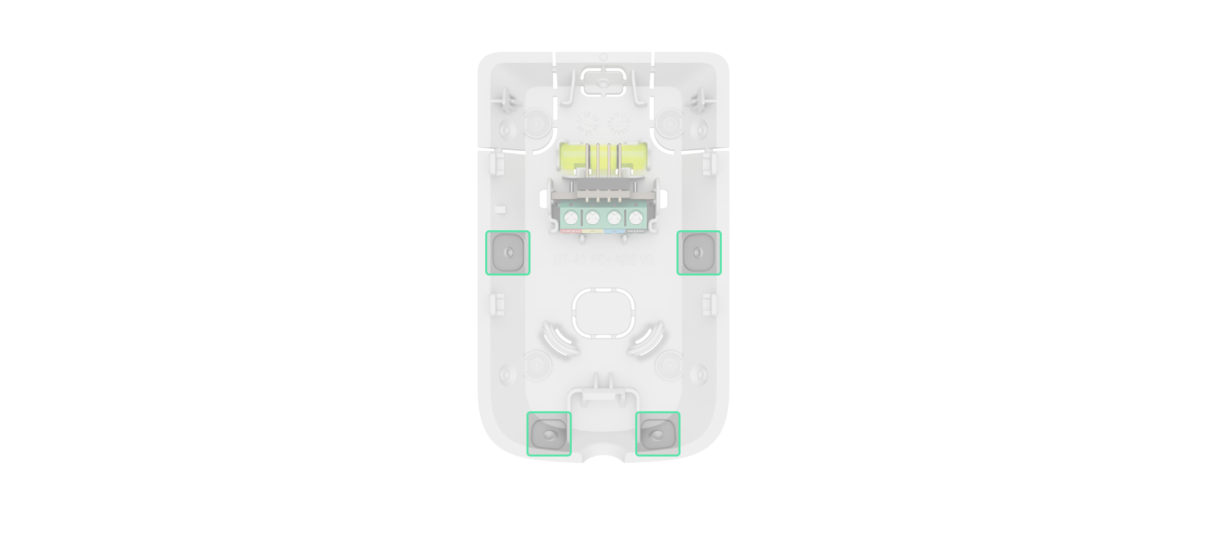
Als het nodig is om de kabel vanaf de onderkant of zijkant om te leiden, maak dan met een boormachine op lage snelheid zorgvuldig gaten op de in de afbeelding aangegeven plaatsen.
- Leid de kabel van de hub door het gemaakte gat in de behuizing van de detector.
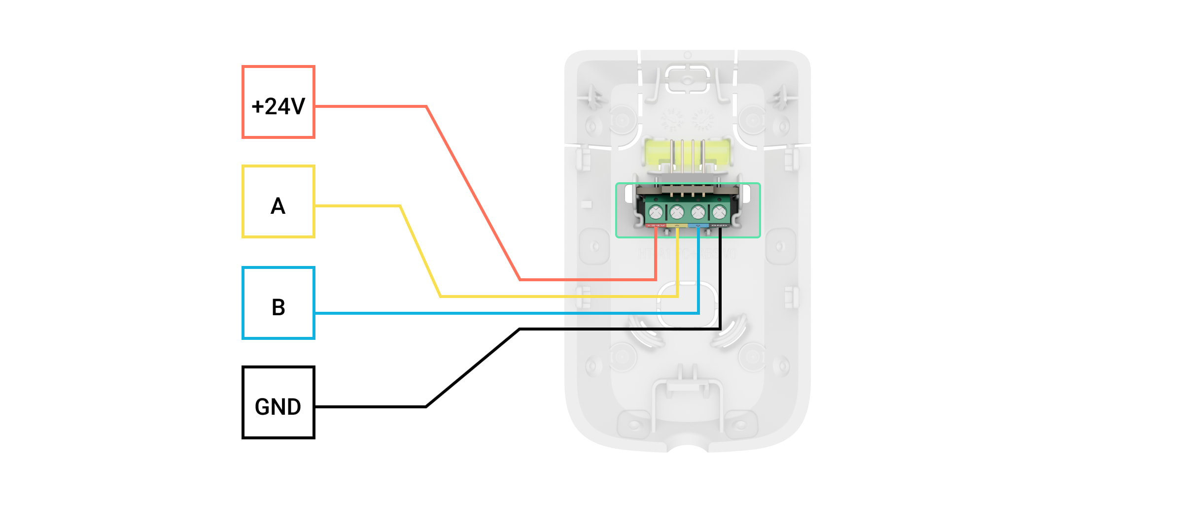
- Sluit de kabels volgens de onderstaande afbeelding op de aansluitklemmen aan. Zorg voor de juiste polariteit en volgorde van de kabelverbindingen. Maak de kabel stevig vast aan de aansluitklemmen.
+24V — 24 V⎓ voedingsaansluiting.
А, B — signaalaansluitingen.
GND — aarde.- Bereid alvast een tweede kabel voor als de detector niet het laatste apparaat op de aansluitkabel is. De uiteinden van de kabel van de eerste en tweede kabel die in de klemmen van de detector worden gestoken, moeten worden vertind of voorzien van een adereindhuls.
- Als Superior MotionProtect G3 Fibra het laatste apparaat op de kabel is en u gebruikt de busaansluiting (radiaal), installeer dan een afsluitweerstand op de twee contacten door deze aan te sluiten op de signaalklemmen van het apparaat. De afsluitweerstand (120 Ohm) hoort bij de volledige set van de hub. Wanneer de Ringverbinding wordt gebruikt, is er geen afsluitweerstand nodig.
We raden aan de ringverbindingsmethode (hub-device-hub) te gebruiken. Als de ring wordt verbroken, wordt geen enkel apparaat uitgeschakeld. In dit geval worden er twee bussen gevormd die normaal blijven werken en gebeurtenissen naar de hub verzenden. Als de ring wordt verbroken, ontvangen de gebruikers en het beveiligingsbedrijf hiervan een melding.
- Bevestig de detector op het SmartBracket-montagepaneel en vergrendel het.
- Zet in de Ajax PRO-app de voeding voor de bussen aan:
- Hub → Instellingen
→ Bussen → Voeding bussen
- Hub → Instellingen
- Voeg de detector toe aan het systeem.
- Voer de functionaliteitstest uit.
- Als de detector de tests doorstaat, bevestigt u het SmartBracket-montagepaneel met de meegeleverde schroeven op een verticaal oppervlak. Gebruik minstens twee bevestigingspunten (een zit in het geperforeerde deel van het paneel boven de sabotagebeveiliging). De sabotagebeveiliging reageert op pogingen om de deksel van de behuizing te breken of open te maken. De melding hierover wordt naar de Ajax-apps verzonden.
Als u SmartBracket in de hoek wilt bevestigen, schroef de meegeleverde schroeven dan in de uitsparingen aan de zijkant. Gebruik minstens twee bevestigingspunten (een zit in het geperforeerde deel van het paneel boven de sabotagebeveiliging).
Als u andere bevestigingsmiddelen gebruikt, let er dan op dat die het montagepaneel niet beschadigen of vervormen.
Dubbelzijdige tape kan alleen als tijdelijke bevestiging worden gebruikt omdat het apparaat elk moment los kan komen van het oppervlak. Zolang het apparaat vastgeplakt is, zal de sabotagebeveiliging niet werken wanneer het apparaat wordt losgemaakt van het oppervlak.
- Bevestig de detector op het SmartBracket-montagepaneel en vergrendel het. Het slot voor de SmartBracket heeft een sabotagebeveiliging en is nodig om de detector veilig te bevestigen en te beschermen tegen snelle demontage. De sabotagebeveiliging reageert als iemand het slot voor SmartBracket probeert te ontgrendelen. De melding hierover wordt naar de Ajax-apps gestuurd.
Toevoegen aan het systeem
Superior MotionProtect G3 Fibra is alleen compatibel met Hub Hybrid (2G) en Hub Hybrid (4G). Alleen geverifieerde partners kunnen Superior-apparaten in de Ajax PRO-apps toevoegen en configureren.
Voordat u een apparaat toevoegt
- Installeer de Ajax PRO-app.
- Log in op een PRO-account of maak een nieuwe aan.
- Selecteer een space of maak een nieuwe aan.
- Voeg minstens één virtuele ruimte toe.
- Voeg een compatibele hub toe aan de space. Zorg dat de hub aanstaat en toegang heeft tot het internet via een ethernetkabel, en/of een mobiel netwerk.
- Zorg ervoor dat de space is uitgeschakeld en de hub niet begint met updaten door de status in de Ajax-app te controleren.
Toevoegen aan de hub
Via de Ajax PRO-app kunt u op twee manieren apparaten toevoegen: automatisch en handmatig.
- Open de Ajax PRO-app. Selecteer de hub waaraan u Superior MotionProtect G3 Fibra wilt toevoegen.
- Ga naar het tabblad Apparaten
en klik op Apparaat toevoegen.
- Selecteer Voeg alle Fibra-apparaten toe. De hub scant dan de Fibra-bussen. Na het scannen worden alle apparaten die op de hub zijn aangesloten maar nog niet aan het systeem zijn toegevoegd weergegeven.
Scannen is ook beschikbaar in het menu Bussen:
Hub → Instellingen
→ Bussen → Voeg alle Fibra-apparaten toe.
- Selecteer het apparaat uit de lijst. Na het indrukken gaat de led-indicator knipperen om dit apparaat te identificeren.
- Stel de naam van het apparaat in en geef de kamer en de beveiligingsgroep op als de Groepsmodus is ingeschakeld.
- Klik op Opslaan.
De detector die verbonden is met de hub verschijnt in de app in de lijst met hub-apparaten.
Het bijwerken van de status van het apparaat is afhankelijk van de Fibra-instellingen. De standaardwaarde is 36 seconden.
Als de verbinding mislukt: controleer dan of de bekabelde verbinding correct is en probeer het opnieuw. Als het maximum aantal apparaten (100 voor Hub Hybrid) wat toegevoegd kan worden aan de hub is bereikt, ontvangt u een foutmelding tijdens het toevoegen.
Superior MotionProtect G3 Fibra werkt alleen met één hub. De detector stopt met het uitwisselen van gegevens met de vorige hub wanneer deze met een nieuwe wordt gekoppeld. Als Superior MotionProtect G3 Fibra aan een nieuwe hub wordt toegevoegd, blijft die in de lijst met apparaten van de vorige hub staan. U kunt deze handmatig verwijderen.
Testen van de functionaliteit
Het Ajax-systeem heeft diverse testen om de juiste installatieplaats voor de apparaten te selecteren. Beschikbaar voor Superior MotionProtect G3 Fibra:
- Fibra-signaalsterktetest — bepaalt de sterkte en stabiliteit van het signaal op de installatieplaats van het apparaat.
- Detectiezonetest — om te controleren hoe de detector reageert op beweging en maskering op de installatieplaats van het apparaat.
- Kalibratie van de maskeringssensor — om de kenmerken van de detectiezone van de detector op de installatieplaats te registreren. Deze kenmerken helpen om maskering te detecteren.
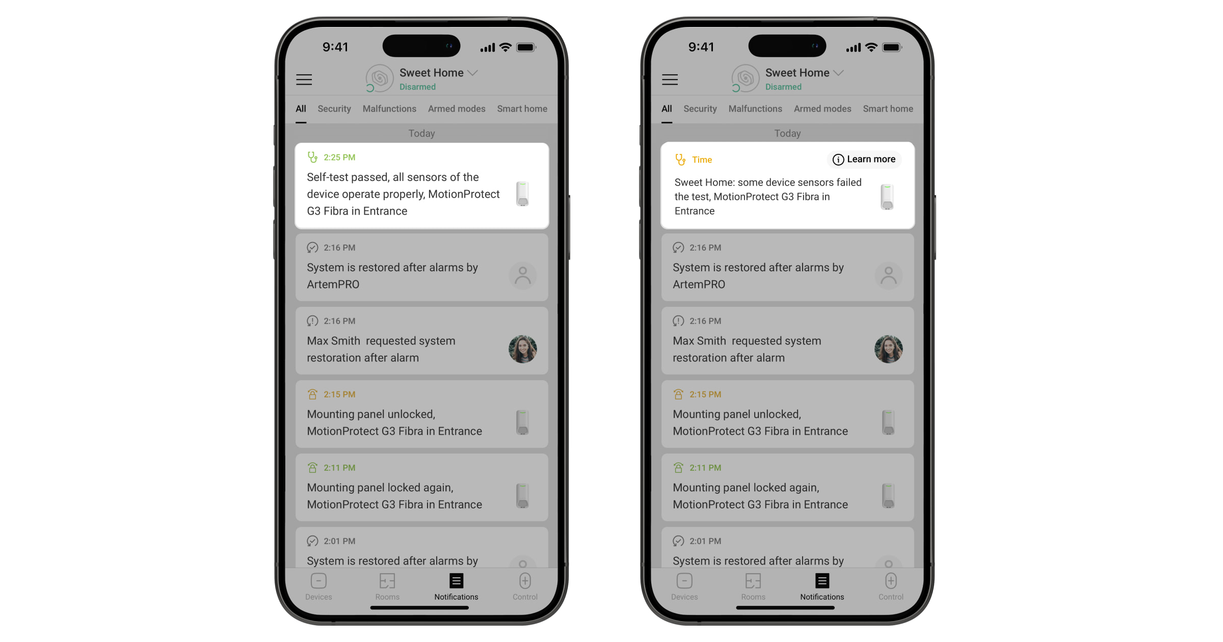
- Zelftest van het apparaat — om te controleren of alle ingebouwde sensoren van de detector goed werken.
Pictogrammen
Pictogrammen in de Ajax-app geven enkele statussen van Superior MotionProtect G3 Fibra weer. Pictogrammen kunnen worden gecontroleerd in het tabblad Apparaten .
| Pictogram | Betekenis |
|
Fibra-signaalsterkte — toont de signaalsterkte tussen de hub en het apparaat. Aanbevolen waarden: 2-3 streepjes. |
|
| Er is een firmware-update beschikbaar. Ga naar de statussen of instellingen van het apparaat om de beschrijving te vinden en start een update. | |
|
Het apparaat werkt in de modus Altijd actief. |
|
| Het slot voor SmartBracket is ontgrendeld. | |
|
Vertraging bij binnenkomst en/of vertrek is ingeschakeld. |
|
|
Het apparaat werkt in de Deelinschakeling. |
|
| Maskering gedetecteerd. | |
|
Apparaat wordt automatisch uitgeschakeld als gevolg van overschrijding van het aantal alarmen. |
|
|
Het apparaat is permanent gedeactiveerd. |
|
|
Meldingen over sabotagealarmen zijn permanent uitgeschakeld. |
|
|
Het apparaat is gedeactiveerd tot de eerste keer dat het systeem wordt uitgeschakeld. |
|
|
Meldingen voor sabotagealarmen zijn gedeactiveerd tot de eerste keer dat het systeem wordt uitgeschakeld. |
|
|
Het apparaat is niet overgezet naar de nieuwe hub. |
Statussen
Het statusscherm bevat informatie over het apparaat en de bedrijfsparameters. De statussen van Superior MotionProtect G3 Fibra zijn te vinden in de Ajax-app:
- Ga naar het tabblad Apparaten
.
- Selecteer Superior MotionProtect G3 Fibra in de lijst.
| Parameter | Betekenis |
| Storing |
Door te klikken op Het veld wordt alleen weergegeven als er een storing is gedetecteerd. |
| Nieuwe firmwareversie beschikbaar |
Als u op Dit veld wordt weergegeven als er een nieuwe firmwareversie beschikbaar is. |
| Temperatuur |
Temperatuur van het apparaat. De toegestane afwijking tussen de waarde in de app en de temperatuur op de plaats van de installatie is 2 °F. De waarde wordt bijgewerkt zodra het apparaat een temperatuurwijziging van minstens 1 °F signaleert. U kunt een scenario op basis van temperatuur configureren om zo automatiseringsapparaten te besturen. |
| Fibra-signaalsterkte |
Signaalsterkte tussen de hub en Superior MotionProtect G3 Fibra. Aanbevolen waarden: 2-3 streepjes. Fibra is een protocol voor het verzenden van gebeurtenissen en alarmmeldingen. |
| Verbinding via Fibra | De verbindingsstatus tussen de hub en het apparaat:
|
| Busspanning | Het voltage op de Fibra-bus waarmee het apparaat is verbonden. |
| Deksel | De status van de sabotagebeveiligingen van het apparaat die reageren op het openen of losmaken van de behuizing van het apparaat:
|
| Montagepaneel | De status van de sabotagebeveiliging die reageert op het ontgrendelen van het slot van het SmartBracket-montagepaneel:
|
| Anti-maskering | De status van de maskeringssensor:
|
| Altijd actief |
Als deze optie ingeschakeld is, is de detector voortdurend ingeschakeld, detecteert hij beweging en slaat hij alarm. |
| Permanente deactivering | Geeft de status van de permanente deactiveringsfunctie van het apparaat weer:
|
| Eenmalige deactivering | Geeft de status van de eenmalige deactiveringsfunctie van het apparaat weer:
|
| Reactie op alarm | |
| Bedrijfsmodus | Toont hoe het apparaat reageert op alarmen:
|
| Vertraging bij binnenkomst |
Vertraging bij binnenkomst (vertraging van alarmactivatie) is de tijd die de gebruiker heeft om het beveiligingssysteem uit te schakelen nadat hij de beveiligde ruimte betreedt. |
| Vertraging bij vertrek |
Vertraging bij vertrek (vertraging bij inschakelen) is de tijd die de gebruiker heeft om de beveiligde ruimte te verlaten na het inschakelen. |
| Inschakelen bij deelinschakeling |
Als deze optie ingeschakeld is, wordt de ingeschakelde modus van het apparaat geactiveerd als het systeem ingesteld is op Deelinschakeling. |
| Deelinschakeling vertraging bij binnenkomst |
Vertraging bij binnenkomst in modus Deelinschakeling. Vertraging bij binnenkomst (vertraging van alarmactivatie) is de tijd die de gebruiker heeft om het beveiligingssysteem uit te schakelen nadat hij de beveiligde ruimte betreedt. |
| Deelinschakeling vertraging bij vertrek |
Tijd voor vertraging bij vertrek in de modus voor Deelinschakeling. Vertraging bij vertrek (vertraging bij inschakelen) is de tijd die de gebruiker heeft om de beveiligde ruimte te verlaten na het inschakelen. |
| Deelinschakeling vertraging |
Vertragingstijd bij binnenkomst in de Deelinschakeling wanneer het apparaat is ingesteld op de bedrijfsmodus Follower. Dit is de tijd die de gebruiker heeft om de Deelinschakeling (vertraging van alarmactivatie) uit te schakelen nadat de in-/uitgangsdetector is geactiveerd. |
| Firmware | Firmwareversie van het apparaat. |
| Apparaat-ID | ID van het apparaat. Ook beschikbaar via de QR-code op de behuizing van het apparaat en de verpakking. |
| Apparaatnr. | Apparaatnummer. Dit nummer wordt verzonden naar de meldkamer bij een alarm of gebeurtenis. |
| Busnummer | Het nummer van de Fibra-bus op de hub waarmee het apparaat verbonden is. Wordt weergegeven bij een Busverbinding (radiaal). |
| Ring nr. | Het nummer van de Fibra-ring op de hub waarmee het apparaat verbonden is. Wordt weergegeven bij een Ringverbinding. |
Instellingen
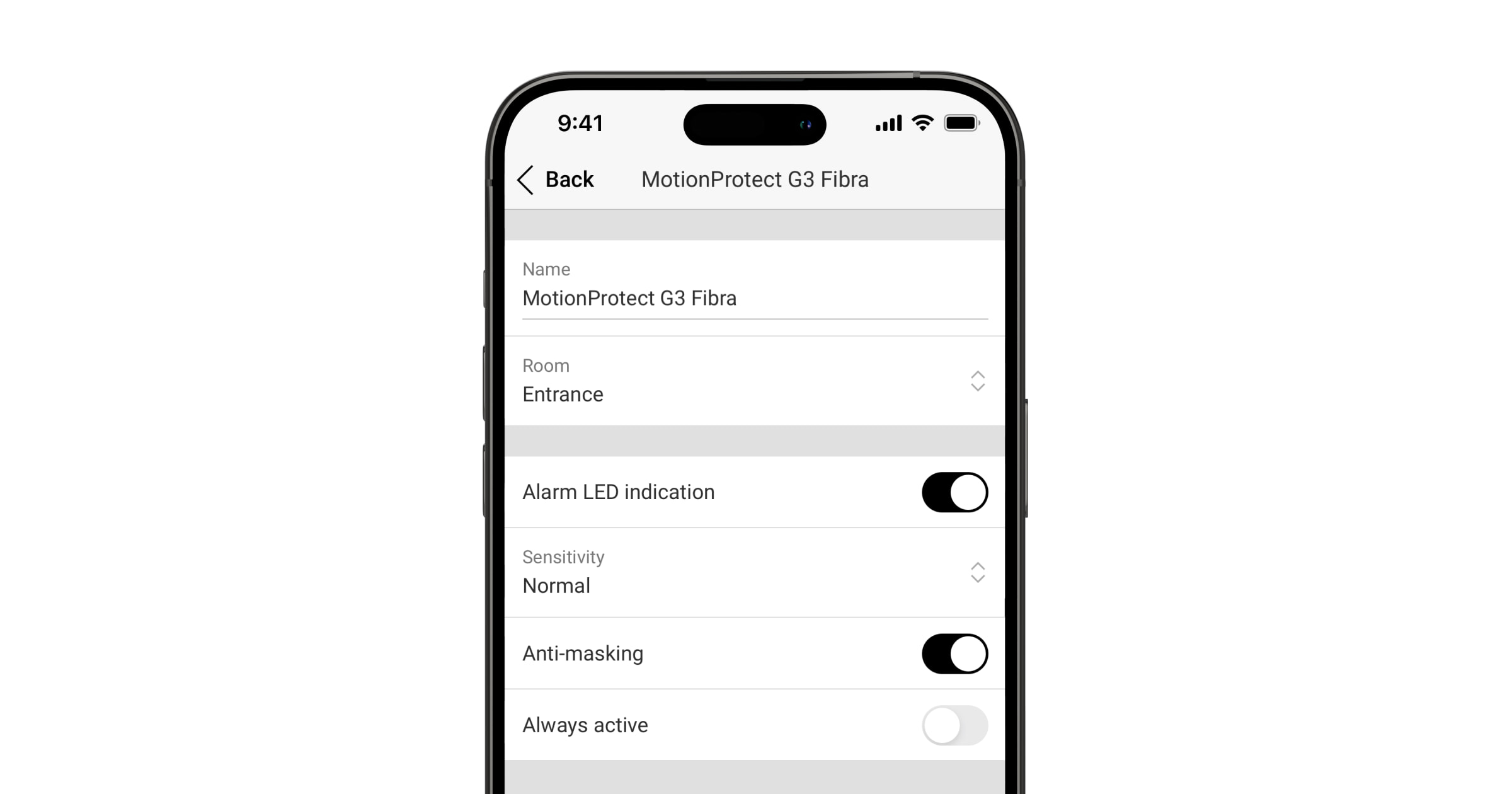
Zo past u de instellingen van Superior MotionProtect G3 Fibra aan in de Ajax-app:
- Ga naar het tabblad Apparaten
.
- Selecteer Superior MotionProtect G3 Fibra in de lijst.
- Ga naar Instellingen
.
- Stel de vereiste instellingen in.
- Klik op Terug om de nieuwe instellingen op te slaan.
| Instellingen | Betekenis |
| Naam |
Naam van het apparaat. Wordt weergegeven in de lijst met apparaten van de hub, tekst van het sms-bericht en meldingen in het logboek. Als u de naam van het apparaat wilt wijzigen, klikt u op het tekstvak. De naam kan uit maximaal 24 Cyrillische tekens of 12 Latijnse tekens bestaan. |
| Ruimte |
De virtuele ruimte selecteren waaraan Superior MotionProtect G3 Fibra is toegewezen. De naam van de ruimte wordt weergegeven in de sms-berichten en meldingen in het logboek. |
| Led-indicatie van alarmen | Wanneer uitgeschakeld, geeft de led-indicator geen melding over alarmen en het activeren van de sabotagebeveiliging. |
| Anti-maskering | Wanneer deze optie is ingeschakeld, detecteert het apparaat maskering. |
| Altijd actief |
Wanneer ingeschakeld, staat de detector altijd in de ingeschakelde modus en detecteert het beweging. |
| Waarschuwing met sirene | |
| Als beweging wordt gedetecteerd | Indien ingeschakeld, worden de aan het systeem toegevoegde sirenes geactiveerd wanneer het apparaat beweging detecteert. |
| Als maskering gedetecteerd wordt |
Indien ingeschakeld, worden de aan het systeem toegevoegde sirenes geactiveerd wanneer het apparaat maskering detecteert. Deze parameter wordt getoond als de optie Anti-maskering is ingeschakeld. |
| Reactie op alarm | |
| Bedrijfsmodus | Bepaal hoe dit apparaat reageert op alarmen:
|
| Vertraging bij binnenkomst |
Selecteer de vertragingstijd bij binnenkomst: 5 tot 255 seconden. Vertraging bij binnenkomst (vertraging van alarmactivatie) is de tijd die de gebruiker heeft om het beveiligingssysteem uit te schakelen nadat hij de beveiligde ruimte betreedt. |
| Vertraging bij vertrek |
Selecteer de vertragingstijd bij vertrek: 5 tot 255 seconden. Vertraging bij vertrek (vertraging bij inschakelen) is de tijd die de gebruiker heeft om de beveiligde ruimte te verlaten na het inschakelen. |
| Inschakelen bij deelinschakeling |
Indien ingeschakeld, schakelt de detector over naar de ingeschakelde modus wanneer het systeem is ingesteld op de Deelinschakeling. |
| Deelinschakeling vertraging bij binnenkomst |
Vertragingstijd Deelinschakeling bij binnenkomst: van 5 tot 255 seconden. Vertraging bij binnenkomst (vertraging van alarmactivatie) is de tijd die de gebruiker heeft om de Deelinschakeling uit te schakelen nadat hij de beveiligde ruimte betreedt. |
| Deelinschakeling vertraging bij vertrek |
Vertragingstijd Deelinschakeling bij vertrek: van 5 tot 255 seconden. Vertraging bij vertrek (vertraging bij inschakelen) is de tijd die de gebruiker heeft om de beveiligde ruimte te verlaten na het inschakelen van de Deelinschakeling. |
| Deelinschakeling vertraging |
Vertraging bij Deelinschakeling: 5 tot 255 seconden. Dit is de tijd die de gebruiker heeft om de Deelinschakeling (vertraging van alarmactivatie) uit te schakelen nadat de in-/uitgangsdetector is geactiveerd. De instelling wordt weergegeven als het apparaat is ingesteld op de bedrijfsmodus Follower en de optie Inschakelen bij deelinschakeling is ingeschakeld. |
| Firmware-update | Schakelt het apparaat naar de modus voor het bijwerken van de firmware als er een nieuwe versie beschikbaar is. |
| Fibra-signaalsterktetest |
Schakelt het apparaat over naar de modus voor de Fibra-signaalsterktetest. Met deze test kunt u de signaalsterkte tussen de hub en het apparaat via het protocol voor bekabelde Fibra-gegevensoverdracht controleren om zo de optimale installatieplaats te bepalen. |
| Detectiezonetest |
Schakelt de detector over naar de modus voor de detectiezonetest. Met deze optie kunnen bewegings– en maskeringssensoren worden getest. De test helpt om te controleren of het apparaat correct is geïnstalleerd om alle alarmen te detecteren. |
| De maskeringssensor kalibreren |
Voert de kalibratie van de maskeringssensor uit om ervoor te zorgen dat het apparaat correct werkt en pogingen om het gezichtsveld te blokkeren direct kan detecteren. |
| Zelftest van het apparaat |
Voert de zelftest van het apparaat uit om te controleren of de ingebouwde sensoren goed werken. De test controleert de IR-bewegingssensor, K-band microgolfsensor en maskeringssensor. |
| Gebruikershandleiding | Opent de gebruikershandleiding van Superior MotionProtect G3 Fibra in de Ajax-app. |
| Permanente deactivering |
Hiermee kan de gebruiker gebeurtenissen van het apparaat uitschakelen zonder het uit het systeem te verwijderen. Er zijn drie opties beschikbaar:
Het systeem kan ook automatisch apparaten uitschakelen wanneer het ingestelde aantal alarmen wordt overschreden. |
| Eenmalige deactivering |
Hiermee kan de gebruiker gebeurtenissen van het apparaat uitschakelen tot de eerste keer dat het apparaat wordt uitgeschakeld. Er zijn drie opties beschikbaar:
|
| Apparaat verwijderen | Ontkoppelt het apparaat, koppelt deze los van de hub en verwijdert de instellingen. |
De maskeringssensor kalibreren
Kalibratie van de maskeringssensor is belangrijk om ervoor te zorgen dat het apparaat correct werkt en pogingen om het gezichtsveld van de sensoren te blokkeren direct kan detecteren. De kalibratie start automatisch wanneer het apparaat aan het systeem is toegevoegd. Als het apparaat er niet in slaagt om de maskeringssensor te kalibreren, stuurt het systeem een melding naar gebruikers en de meldkamer en geeft het de betreffende fout weer in de statussen van het apparaat.
U kunt de kalibratie van de maskeringssensor handmatig starten, bijvoorbeeld als de automatische kalibratie mislukt of als de installatielocatie van het apparaat is gewijzigd.
Voordat u met de kalibratie begint, moet u ervoor zorgen dat het apparaat correct is geïnstalleerd en dat er niets het gezichtsveld blokkeert.
Om te beginnen met het kalibreren van de maskeringssensor, in de Ajax app:
- Ga naar het tabblad Apparaten
.
- Selecteer Superior MotionProtect G3 Fibra in de lijst.
- Ga naar Instellingen
.
- Ga naar het menu Kalibratie van maskeringssensor.
- Klik op Start.
- Als de kalibratie geslaagd is, klikt u op Sluiten om terug te keren naar de instellingen. Als het apparaat de maskeringssensor niet kan kalibreren, controleer dan of deze correct is geïnstalleerd en of er niets het gezichtsveld blokkeert. Klik vervolgens op Herstarten.
Zelftest van het apparaat
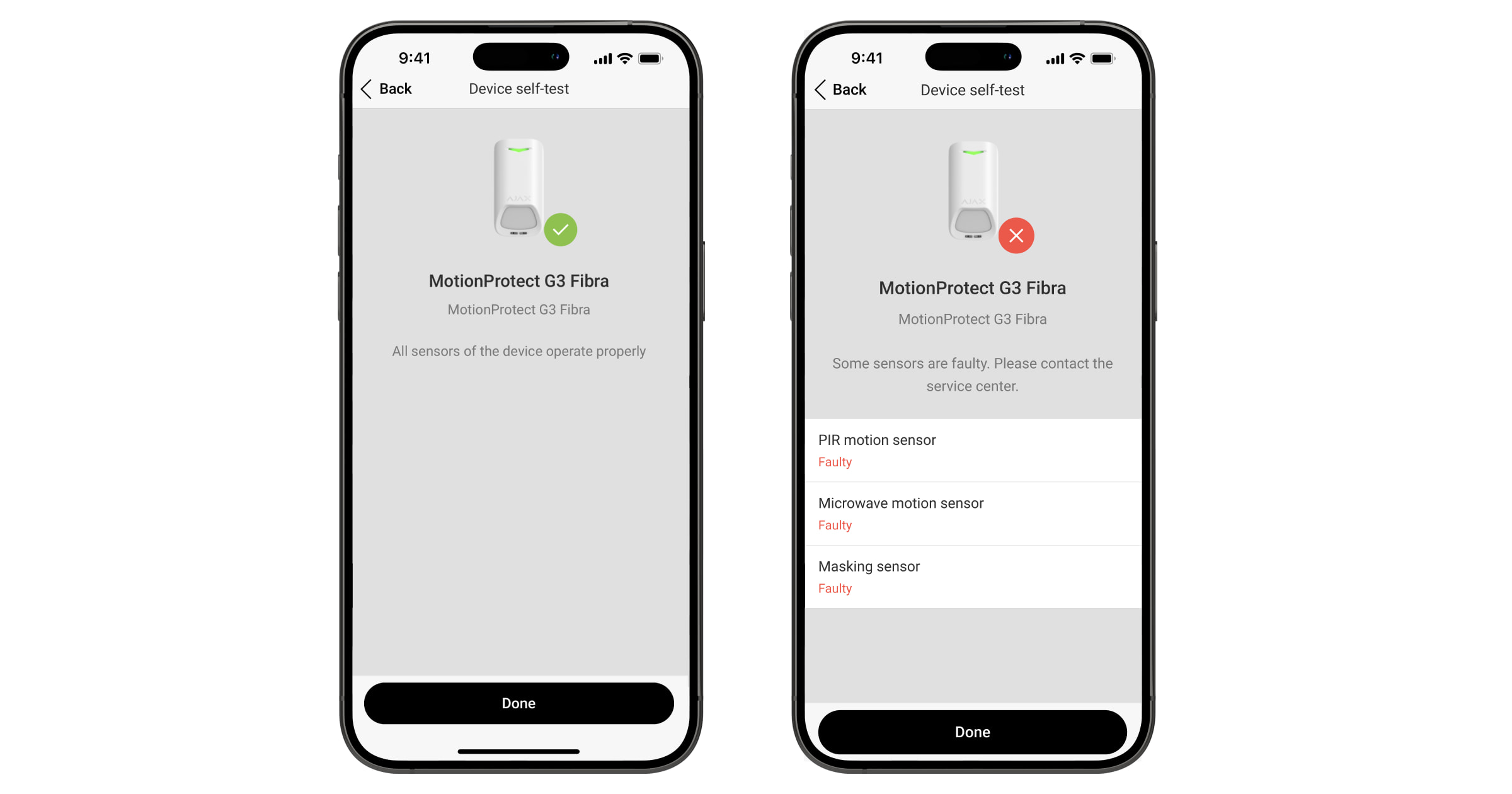
Met de zelftest van het apparaat kunnen gebruikers controleren of de ingebouwde sensoren van het apparaat goed werken. Tijdens de zelftest worden de IR-bewegingssensor, de K-band-microgolfsensor en de maskeringssensor getest. Het apparaat voert regelmatig automatisch een zelftest uit van de ingebouwde sensoren. Als er een storing wordt gedetecteerd, waarschuwt het systeem de gebruikers en de meldkamer.
Bovendien kan de zelftest van het apparaat handmatig worden gestart in de Ajax-apps.
Voordat u een zelftest uitvoert, moet u ervoor zorgen dat het systeem is uitgeschakeld en dat er geen andere test wordt uitgevoerd.
Zo voert u een zelftest uit in de Ajax-app:
- Ga naar het tabblad Apparaten
.
- Selecteer Superior MotionProtect G3 Fibra in de lijst.
- Ga naar Instellingen
.
- Ga naar het menu Zelftest van het apparaat.
- Klik op Start.
- Als de zelftest geslaagd is, klikt u op Klaar om terug te keren naar de instellingen. Als sommige sensoren defect zijn, raden we aan contact op te nemen met het servicecentrum.
Gebruikers en de meldkamer ontvangen na afloop een bericht over het testresultaat.
Indicatie
De led-indicatie van Superior MotionProtect G3 Fibra kan rood of groen oplichten, afhankelijk van de status van het apparaat.
| Indicatie | Gebeurtenis | Opmerking |
| Brandt 0,3 seconde groen en gaat drie keer 0,3 seconden uit. | Het apparaat detecteert een alarm wanneer het niet aan de hub is toegevoegd. | |
| Brandt 0,3 seconde groen en gaat zes keer 0,3 seconden uit. | Het apparaat is van de hub verwijderd. | |
| Knippert snel groen. | Het apparaat wordt geselecteerd uit de lijst met apparaten die zijn gevonden door de Fibra-bussen te scannen om het toe te voegen aan de hub. | |
| Licht groen op voor ongeveer 0,6 seconden. |
|
|
| Brandt continu groen en gaat voor 0,6 seconden uit wanneer beweging is gedetecteerd. | De detectiezonetest van de bewegingssensor wordt uitgevoerd voor het apparaat. | Meer informatie |
| Brandt continu rood en gaat volledig uit wanneer maskering is gedetecteerd. Wanneer de maskering verwijderd is, licht het lampje weer rood op. | De detectiezonetest van de maskeringssensor wordt uitgevoerd voor het apparaat. | Meer informatie |
| Brandt 0,5 seconde groen en gaat 0,5 seconden uit. | De maskeringssensor wordt gekalibreerd. | Meer informatie |
| Brandt ongeveer 1 seconde rood elke 4 seconden. | Het apparaat heeft een hardwarefout of de sensoren werken niet goed. | Het apparaat heeft onderhoud nodig; neem contact op met onze Technische Ondersteuning. |
| Brandt ongeveer 1 seconde rood elke 13 seconden. | De kalibratie van de maskeringssensor is mislukt. |
Zorg ervoor dat het apparaat correct is geïnstalleerd en dat niets het gezichtsveld blokkeert. Start vervolgens de kalibratie opnieuw. Neem contact op met onze Technische Ondersteuning als de indicatie zich herhaalt. |
Storingen
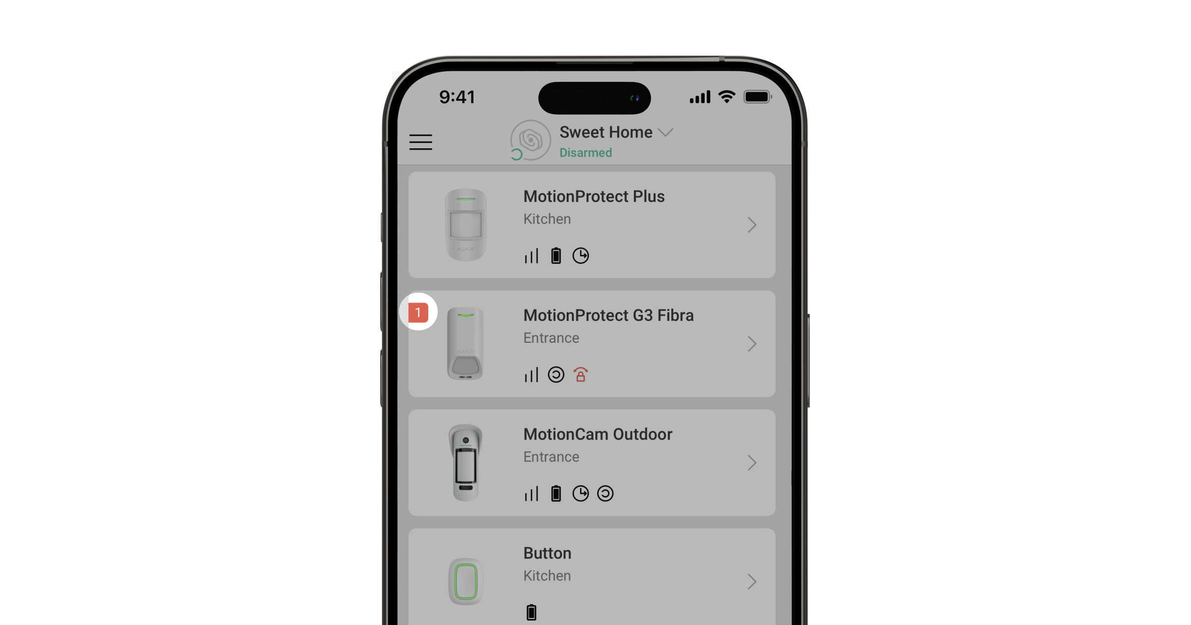
Wanneer het apparaat een storing detecteert (er is bijvoorbeeld geen verbinding via het Fibra-protocol), wordt in de Ajax-app linksboven bij het apparaatpictogram een storingsteller weergegeven.
Alle storingen worden weergegeven in de statussen van het apparaat. Velden met storingen worden rood gemarkeerd.
Een storing wordt weergegeven als:
- De temperatuur van het apparaat buiten de aanvaardbare grenzen valt.
- Het slot van het montagepaneel van het apparaat is ontgrendeld (de sabotagebeveiliging is geactiveerd).
- Het deksel van de detector open is (sabotagebeveiliging is geactiveerd).
- Er geen signaal via het Fibra-protocol is.
- De IR-sensor is defect.
- De K-band microgolfsensor is defect.
- De openingssensor is defect.
- De kalibratie van de maskeringssensor is mislukt.
Onderhoud
Controleer regelmatig het functioneren van het apparaat. De optimale testfrequentie is elke drie maanden. Verwijder stof, spinnenwebben en ander vuil van de behuizing van de detector. Gebruik een zachte, droge doek die geschikt is voor het onderhoud van de apparatuur.
Gebruik geen middelen die alcohol, aceton, benzine of andere actieve oplosmiddelen bevatten om het apparaat te reinigen.
Technische specificaties
Garantie
De garantie op de producten van de Limited Liability Company ‘Ajax Systems Manufacturing’ is na aankoop twee jaar geldig.
Indien het apparaat niet goed functioneert, raden we u aan om eerst contact op te nemen met de ondersteuningsdienst. De meeste technische problemen kunnen op afstand worden opgelost.
Contact opnemen met de technische ondersteuning:
Gefabriceerd door “AS Manufacturing” LLC
