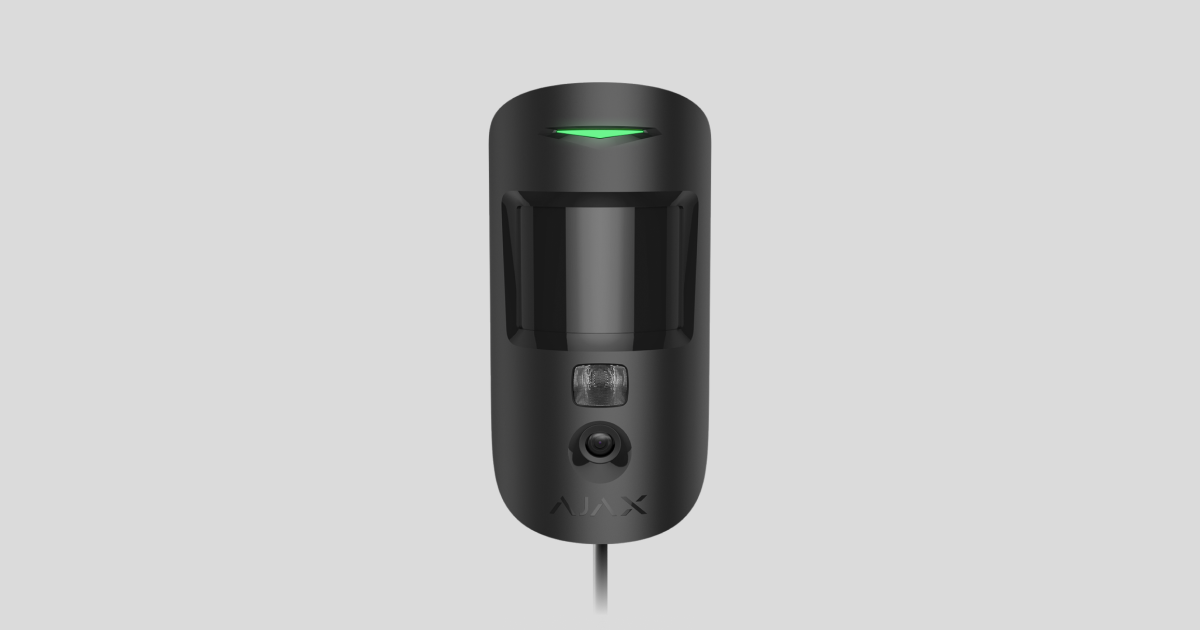
Superior MotionCam (PhOD) Fibra é um detetor de movimentos IV com fios que suporta as funcionalidades Fotos por alarme, Fotos por pedido, Fotos por cenários, Fotos por programação e Fotos ao armar/desarmar. O dispositivo destina-se exclusivamente a uso em ambientes interiores. Deteta movimento a uma distância de até 12 metros. Ignora animais de estimação quando instalado e configurado corretamente.
É necessário um hub Ajax para que o detetor funcione. Superior MotionCam (PhOD) Fibra é compatível com Superior Hub Hybrid (2G) e Superior Hub Hybrid (4G) em OS Malevich 2.15.2 ou superior. Não está prevista a ligação a outros hubs, repetidores de sinal de rádio, ocBridge Plus e uartBridge.
Superior MotionCam (PhOD) Fibra faz parte de um sistema Ajax e troca dados com o hub utilizando o protocolo seguro de comunicação por cabo Fibra. A comunicação por cabo pode atingir os 2000 metros de comprimento quando ligada com o cabo de par entrançado U/UTP cat.5.
Superior MotionCam (PhOD) Fibra está relacionado com a linha de produtos Fibra de dispositivos com fios. Apenas os parceiros acreditados da Ajax Systems podem comprar, instalar e administrar produtos Fibra.
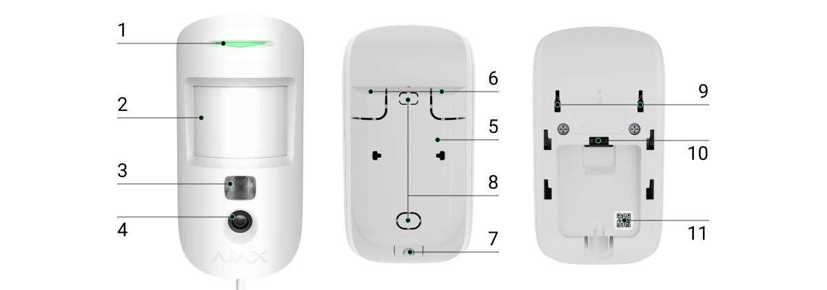
Elementos funcionais
- Indicador LED.
- Lente de deteção de movimentos.
- Retroiluminação por infravermelhos (IV). Utilizado para tirar fotografias em condições de escuridão e pouca luz.
- Câmara.
- Painel de instalação SmartBracket. Para retirar o painel, faça-o deslizar para baixo.
- Parte perfurada do painel de instalação. Necessário para acionar uma sabotagem em caso de tentativa de desprender o detetor da superfície. Não as parta!
- O orifício para fixar o painel SmartBracket com um parafuso.
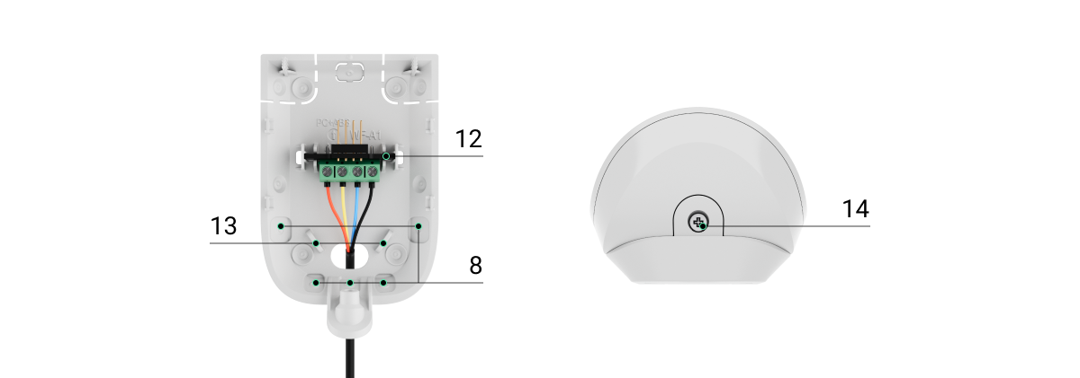
- Locais para os cabos.
- Botão de tamper anti-sabotagem. Alertas de tentativas de retirar o detetor da superfície ou de o retirar do painel de instalação.
- Tomada de ligação da régua de terminais.
- Código QR com o ID do dispositivo. É utilizado para emparelhar o dispositivo com um hub Ajax.
- Régua de terminais para a ligação do detetor.
- Os furos para fixar os fios com abraçadeiras.
- Parafuso de fixação. É utilizado para fixar o detetor no painel de instalação.
Princípio do funcionamento
Superior MotionCam (PhOD) Fibra é um detetor de movimento com fios que suporta a verificação fotográfica. Depois de detetar o movimento, capta uma série de imagens, o que permite avaliar o que está a acontecer na instalação em dinâmica. Isto alivia os utilizadores de uma ansiedade desnecessária e as empresas de segurança de envios desnecessários de patrulhas.
Quando um detetor armado identifica um movimento, envia instantaneamente um alarme para o hub. O painel de controlo ativa as sirenes ligadas ao sistema, desencadeia os cenários e avisa os utilizadores e a empresa de segurança. O registo da app Ajax apresenta todos os alarmes e eventos. As notificações contêm o nome do hub, o nome do dispositivo e a sala virtual à qual o detetor está atribuído.
Superior MotionCam (PhOD) Fibra está equipado com um botão de tamper e uma bateria. O tamper reage se alguém tentar partir ou abrir a tampa da carcaça. Se for ativado, a notificação é enviada para as apps Ajax. A bateria é utilizada quando o detetor tira uma fotografia, ativa uma retroiluminação IV e transmite um alarme. Isto reduz o consumo atual na linha à qual o detetor está conectado e aumenta a autonomia do detetor e do sistema.
Protocolo de transferência de dados Fibra
O detetor utiliza a tecnologia Fibra para transmitir alarmes e eventos. É um protocolo de transferência de dados com fios para uma comunicação bidirecional rápida e fiável entre o hub e os dispositivos conectados.
Verificação fotográfica
A verificação fotográfica permite-lhe avaliar o que está a acontecer nas instalações. Estão disponíveis quatro tipos de verificação fotográfica para o Superior MotionCam (PhOD) Fibra:
- Foto por alarme.
- Foto por pedido.
- Foto por cenário.
- Foto por programação.
- Foto ao armar/desarmar.
O detetor só tira Fotos por alarme se for detetado movimento e apenas quando o modo armado está ativado. Por predefinição, a função Foto por alarme está ativada para todos os detetores.
O detetor não muda instantaneamente para o modo armado. O tempo de comutação depende de dois fatores: o atraso de saída (especificado nas definições do detetor) e o intervalo de ping entre o hub e o detetor. O intervalo de ping especificado nas definições do hub , secção Jeweller/Fibra, por defeito o seu significado é 36 segundos.
No primeiro caso, o atraso é definido por um administrador ou por um utilizador PRO com direitos de administrador. No segundo caso, o atraso ocorre porque o hub demora um intervalo de ping para notificar o detetor sobre a alteração do modo de segurança.
A função de Foto por pedido é útil para verificar a situação nas instalações. Dependendo das definições, as fotografias podem ser tiradas em qualquer altura ou quando o Superior MotionCam (PhOD) Fibra está armado. Por defeito, a funcionalidade Foto por pedido está desativada para todos os utilizadores.
Quando a opção Fotos por cenários está ativada, o Superior MotionCam (PhOD) Fibra tira fotografias em caso de alarme a partir de dispositivos Ajax especificados. Por predefinição, a funcionalidade Foto por cenário está desativada para todos os detetores.
A funcionalidade Foto por programação permite aos utilizadores criar um cenário para detetores de movimentos com verificação fotográfica. Estes detetores tiram fotografias de acordo com o horário.
A funcionalidade Fotos ao armar/desarmar permite aos utilizadores receber fotografias de uma câmara incorporada quando o estado de segurança muda. Com esta funcionalidade, pode verificar a situação na instalação quando o sistema está armado, desarmado ou comutado para modo Noturno.
Ajax Systems também tem o detetor sem o suporte das funcionalidades de Foto por pedido, Fotos por cenários, Foto por programação, e Foto ao armar/desarmar. Este produto chama-se Superior MotionCam Fibra.
A câmara incorporada pode captar de 1 a 5 imagens com uma resolução de 160 × 120 e 320 × 240 píxeis, bem como até 3 imagens com uma resolução de 640 × 480 píxeis.
O detetor possui uma retroiluminação IV para fotografar no escuro, que se ativa com luz insuficiente. Superior MotionCam (PhOD) Fibra tira fotografias a preto e branco quando fotografa nestas condições.
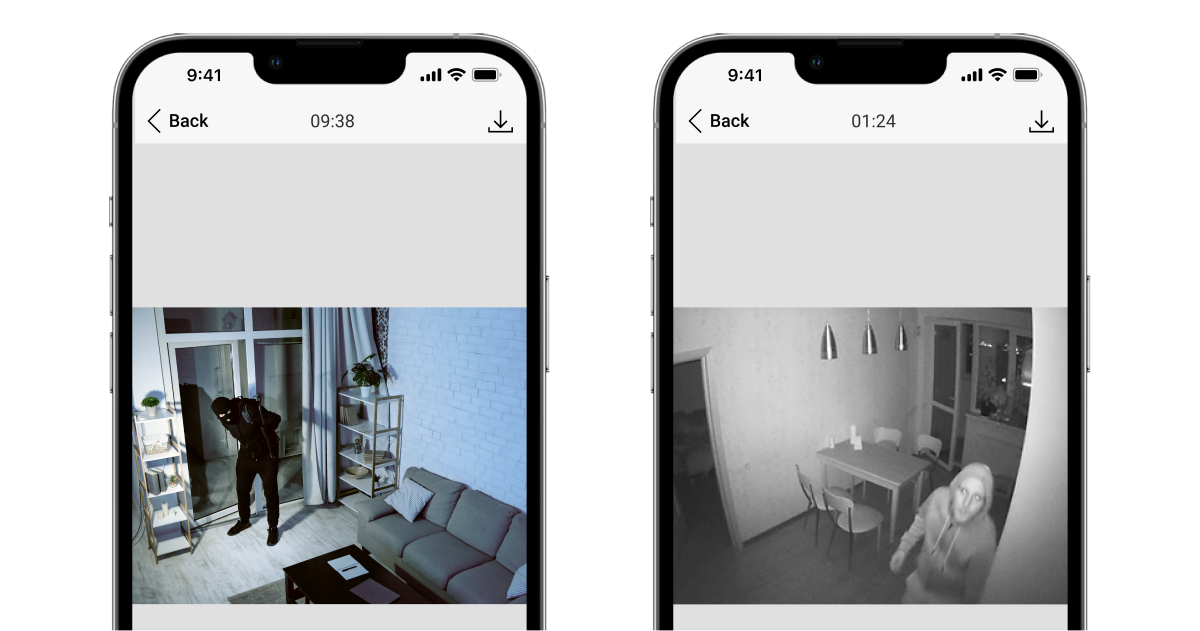
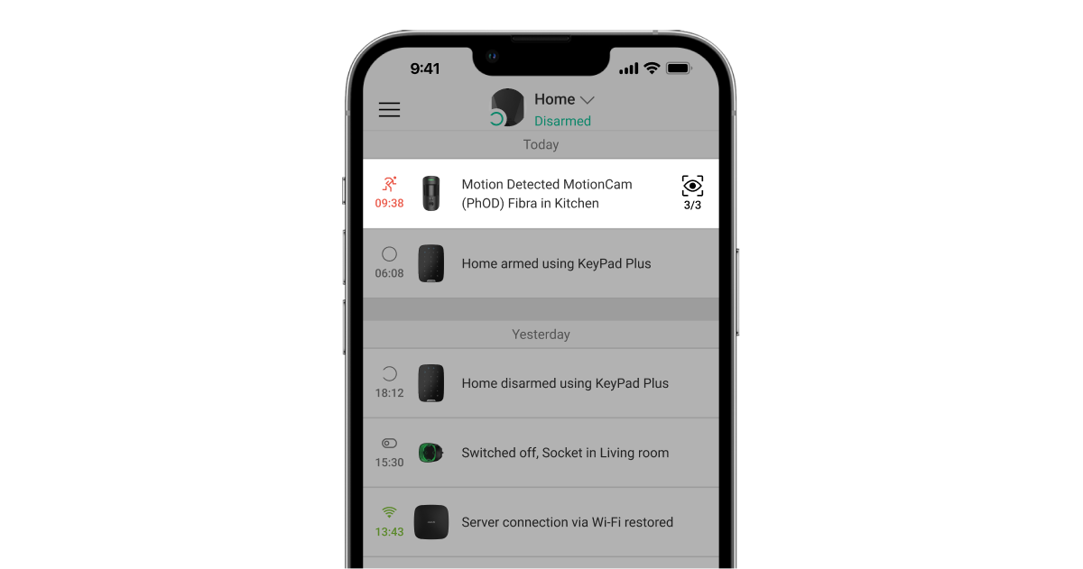
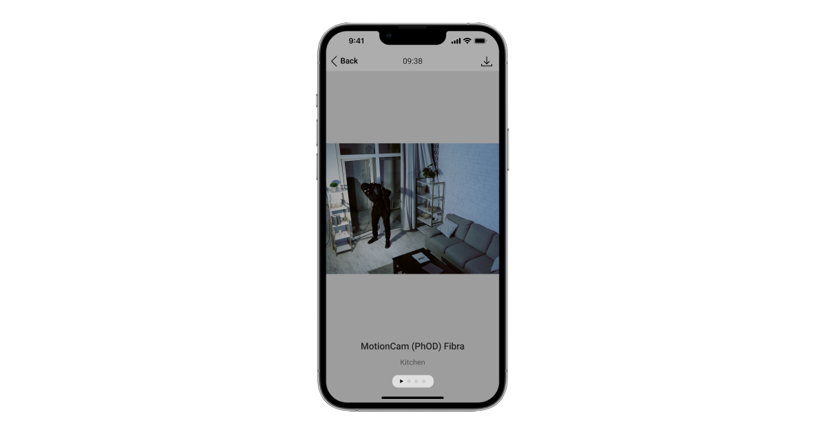
As fotografias podem ser apresentadas na app como uma imagem ou uma série animada (se for tirada mais do que uma fotografia). O número de imagens é configurado em apps Ajax. Para ver as fotografias recebidas, clique na notificação do Superior MotionCam (PhOD) Fibra no historial de eventos.
Pode ver todas as fotografias da série animada individualmente, clicando no ícone na parte inferior do ecrã.
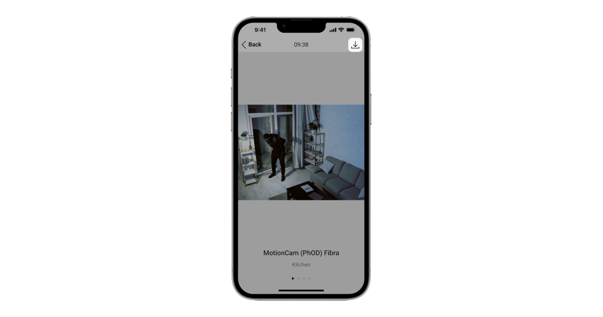
Pode guardar a verificação fotográfica como vídeo ou imagens, clicando no ícone de descarregar.
Tempo de entrega de fotografias
O tempo de entrega das fotografias às apps Ajax depende da resolução da imagem, intensidade do sinal Fibra e da velocidade da ligação à Internet. As mensagens de alarme são entregues imediatamente, independentemente das definições.
A tabela mostra o tempo de entrega de uma fotografia quando a intensidade do sinal entre o hub e o Superior MotionCam (PhOD) Fibra é de 2-3 barras e o hub está ligado via Ethernet ou 4G (LTE).
| Resolução fotográfica | Tempo de entrega |
| 160 × 120 pixeis | até 7 segundos |
| 320 × 240 pixeis (predefinição) |
até 9 segundos |
| 640 × 480 pixeis | até 20 segundos |
Compensação da temperatura
A compensação da temperatura é necessária para a resposta do detetor aos movimentos, mesmo que a temperatura ambiente seja próxima da temperatura do corpo humano. Leia mais sobre a compensação de temperatura neste artigo.
Imunidade a animais de estimação
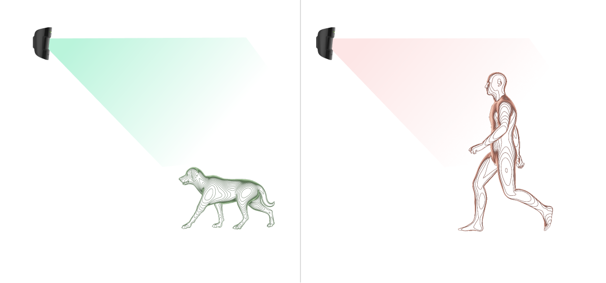
Quando corretamente instalado e configurado, o Superior MotionCam (PhOD) Fibra não reage a animais de estimação com peso até 20 kg e altura inferior a 50 cm. Para instalar e configurar o detetor, siga as nossas recomendações.
Envio de eventos para a central de monitorização
O sistema de segurança Ajax pode transmitir alarmes para a app de monitorização PRO Desktop e para a central recetora de alarmes (CRA) nos formatos SurGard (Contact ID), SIA DC-09 (SIA-DCS), ADEMCO 685 e outros protocolos.
Superior MotionCam (PhOD) Fibra pode transmitir os seguintes eventos:
- Alarme de movimento.
- Verificações fotográficas do alarme de Superior MotionCam (PhOD) Fibra.
- Foto por cenário.
- Foto por programação.
- Foto ao armar/desarmar.
- Alarme de tamper. Recuperação de tamper.
- Perda de comunicação com o hub. Restabelecimento da conexão.
- Desativação / ativação permanente do detetor.
- Alarme devido a perda da alimentação elétrica principal. Restabelecimento da alimentação elétrica principal.
Os dispositivos Ajax são endereçáveis, o que significa que a app PRO Desktop e a CRA recebem eventos, tipo de dispositivo, nome atribuído e localização (sala, grupo). A lista de parâmetros transmitidos pode variar consoante o tipo de CRA e o protocolo de comunicação selecionado.
Pode encontrar o ID do dispositivo, o número do bucle (zona) e o número da linha nos Estados do dispositivo.
As fotos são enviadas para a estação de monitorização da empresa de segurança se a CRA suportar verificação de fotos. Uma lista destes CRAs está disponível aqui.
PRO Desktop suporta receber verificação de fotografias sem ligação adicional.
Seleção do local de instalação
Ao escolher um local para instalar o Superior MotionCam (PhOD) Fibra, tenha em conta os parâmetros que afetam o funcionamento do dispositivo:
- Intensidade do sinal Fibra.
- O comprimento do cabo usado para conectar o detetor ao hub.
- Zona de deteção de movimento.
- O ângulo de visão da câmara e a presença de obstáculos à sua frente.
Siga estas recomendações ao conceber o projeto do sistema Ajax para um objeto. O sistema de segurança deve ser concebido e instalado por profissionais. A lista de parceiros autorizados do Ajax está disponível aqui.
Superior MotionCam (PhOD) Fibra não pode ser instalado
- No exterior. Isto pode danificar o detetor.
- Em locais onde objetos e estruturas possam bloquear a visão do detetor e da câmara. Por exemplo, atrás de uma flor ou de uma coluna.
- Em locais onde as estruturas de vidro podem obstruir a visão do detetor; este não deteta movimentos por detrás do vidro.
- Virado para a janela para evitar que os raios solares diretos atinjam a lente do detetor. Isto pode dar origem a falsos alarmes do detetor de movimentos no modo armado.
- Em frente a quaisquer objetos com mudanças rápidas de temperatura — por exemplo, aquecedores elétricos e a gás, condicionadores de ar. Isto pode dar origem a falsos alarmes do detetor de movimentos no modo armado.
- Em frente a quaisquer objetos em movimento com uma temperatura próxima da do corpo humano — por exemplo, em frente às cortinas oscilantes por cima de um radiador. Isto pode dar origem a falsos alarmes do detetor de movimentos no modo armado.
- Em locais com rápida circulação de ar — por exemplo, perto de ventoinhas, aparelhos de ar condicionado, janelas abertas ou portas. Isto pode dar origem a falsos alarmes do detetor de movimentos no modo armado.
- Interior de instalações com valores de temperatura e humidade que não correspondem aos parâmetros de funcionamento. Isto pode danificar o detetor.
- Em locais com uma intensidade de sinal Fibra baixa ou instável.
Intensidade do sinal Fibra
A intensidade do sinal Fibra é determinada pelo rácio entre o número de pacotes de dados não entregues ou corrompidos e o número de pacotes de dados esperados num determinado período de tempo. O ícone no separador Dispositivos
nas apps Ajax indica a intensidade do sinal:
- Três barras — excelente intensidade do sinal.
- Duas barras — boa intensidade de sinal.
- Uma barra — fraca intensidade de sinal, não é garantido um funcionamento estável.
- Ícone riscado — sem sinal; o funcionamento estável não é garantido.
Os seguintes fatores afetam a intensidade do sinal:
- O número de dispositivos na linha Fibra.
- Comprimento e tipo do cabo.
- A conexão correta dos cabos aos terminais.
Área de deteção do detetor de movimentos
A localização do detetor determina a área a ser monitorizada e a eficácia do sistema de segurança. Ao selecionar o local de instalação, tenha em conta a direção da lente do detetor, os ângulos de visão e a presença de obstáculos à visão da lente.
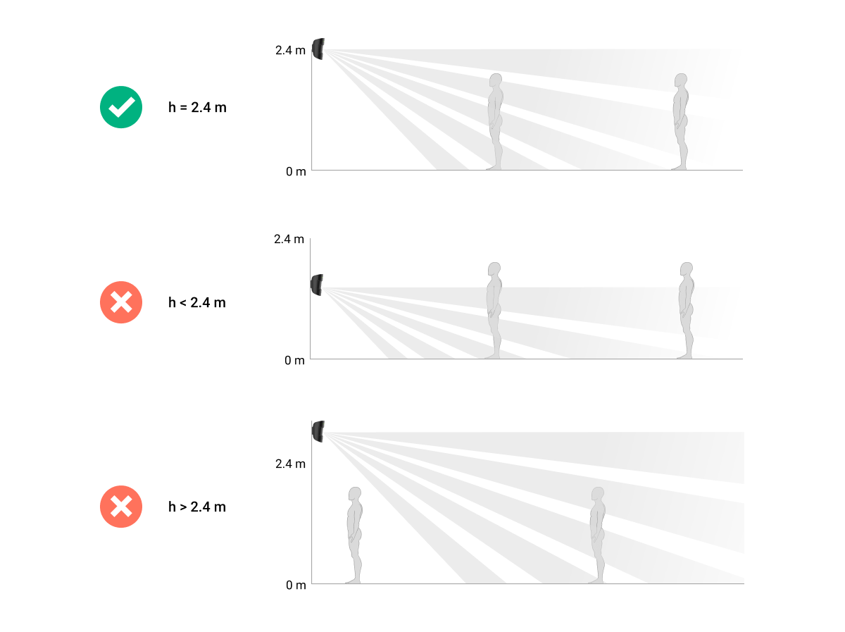
O detetor pode reconhecer movimentos a uma distância de até 12 metros. A direção da lente do detetor deve ser perpendicular ao caminho de entrada para as instalações. Certifique-se de que os móveis, as plantas, os vasos e os elementos decorativos ou de vidro não obstruem a visão do detetor, ou da sua câmara.


Quando instalar o detetor, faça o Teste da Zona de Deteção. Isto permite-lhe verificar o funcionamento do dispositivo e determinar com precisão o sector em que o detetor regista o movimento. Se possível, tire algumas fotografias no local de instalação para garantir que a câmara capta a área pretendida e que não existem obstáculos a bloquear a sua visão.
Conceção e preparação
É fundamental conceber corretamente o projeto do sistema para instalar e configurar corretamente os dispositivos. O projeto deve ter em conta o número e os tipos de dispositivos no objeto, a sua localização exata e a altura de instalação, o comprimento das linhas Fibra com fios, o tipo de cabo utilizado e outros parâmetros. Consulte o artigo para obter dicas sobre como conceber o projeto do sistema Fibra.
Ao conceber o projeto, tenha em conta o esquema de ligação dos cabos de alimentação instalados na instalação. Coloque cabos de sinal a uma distância de pelo menos 50 cm dos cabos de energia em paralelo. Em caso de uma interseção, mantenha um ângulo de 90° entre os condutores.
Antes da instalação, verifique os cabos quanto a dobras e danos físicos. Durante a instalação, respeite o raio de curvatura indicado pelo fabricante nas especificações do cabo. Caso contrário, existe o risco de danificar ou partir o condutor.
Podem ser ligados diferentes tipos de dispositivos à mesma linha Fibra. Por exemplo, é possível utilizar detetores de abertura, sirenes, teclados e Superior MotionCam (PhOD) Fibra na mesma linha.
Se estiver a ligar vários dispositivos a uma única linha Fibra, certifique-se de que estão ligados um a seguir ao outro, como mostra o diagrama.

Os sistemas Ajax também suportam topologias de Feixe e Anel.
Comprimento e tipo do cabo
Tipos de cabos recomendados:
- U/UTP cat.5 4 × 2 × 0,51, condutor de cobre.
- Cabo de sinal 4 × 0,22, condutor de cobre.
O alcance da conexão com fios pode variar se utilizar um tipo de cabo diferente. Não foram testados outros tipos de cabos.
Verificação com um calculador
Para garantir que o projeto é concebido corretamente e que o sistema funcionará na prática, desenvolvemos um Calculador da fonte de alimentação Fibra. O calculador ajuda a verificar a qualidade da comunicação e o comprimento do cabo para os dispositivos Fibra com fios ao conceber o projeto do sistema para a configuração selecionada.
Pode conectar até 100 dispositivos ao Hub Hybrid (com configurações padrão).
Preparação da instalação
Disposição dos cabos
Ao preparar a passagem dos cabos, verifique os regulamentos de segurança elétrica e contra incêndios da sua região. Respeite rigorosamente estas normas e regulamentos. Este artigo fornece sugestões para a disposição dos cabos.
Passagem de cabos
Recomendamos que leia atentamente a secção Seleção do local de instalação antes da instalação. Evite desvios em relação ao projeto do sistema. A violação das regras básicas de instalação e das recomendações deste manual pode levar a um funcionamento incorreto e à perda de ligação com o Superior MotionCam (PhOD) Fibra. Neste artigo estão disponíveis sugestões para o encaminhamento de cabos.
Preparação dos cabos para conexão
Remova a camada isolante e descasque o cabo com um descascador de isolamento especial. As extremidades dos fios inseridos nos terminais do dispositivo devem ser estanhadas ou cravadas com uma manga. Isto garante uma conexão fiável e protege o condutor da oxidação. Conselhos para a preparação dos cabos estão disponíveis neste artigo.
Instalação e conexão
Antes de instalar o Superior MotionCam (PhOD) Fibra, certifique-se de que a localização ideal do detetor foi selecionada e que cumpre os requisitos deste manual. Antes da instalação final, faça o teste de alimentação da linha, o teste da zona de deteção e o teste de intensidade do sinal Fibra. Durante a instalação, cumpra as regras e os requisitos dos atos jurídicos regulamentares sobre segurança elétrica.
Ligação do Superior MotionCam (PhOD) Fibra ao hub
- Desligue a energia das linhas na app Ajax PRO. A função está disponível no menu Linhas:
Hub → Definições→ Linhas → Fonte de alimentação das linhas.
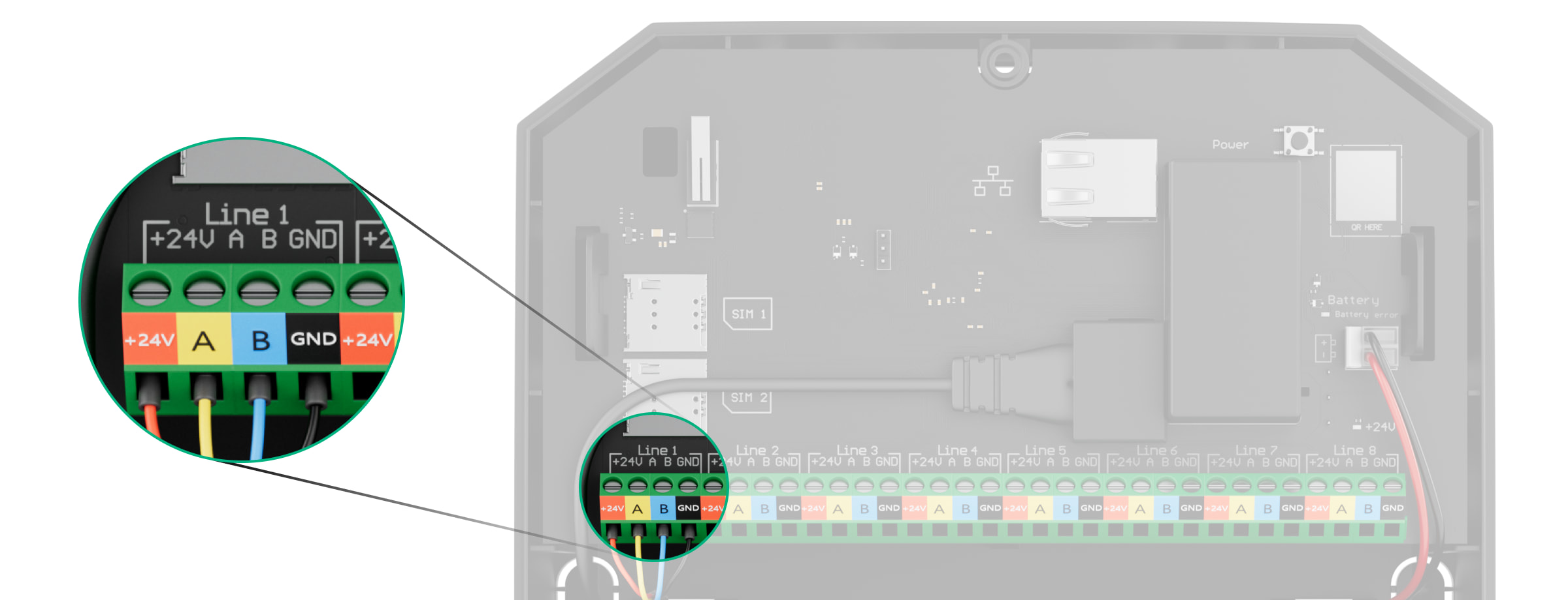
- Encaminhe o cabo para conectar o Superior MotionCam (PhOD) Fibra à carcaça do hub. Conecte os fios à linha do hub necessária.
+24V — Terminal de alimentação de 24 V⎓.
А, B — terminais de sinal.
GND — terra. - Retire o painel de montagem do SmartBracket do detetor. Parta cuidadosamente a parte perfurada correspondente para fazer sair o cabo pela parte traseira (superior ou inferior).
Se for necessário sair com o cabo pela parte inferior ou lateral, faça furos cuidadosamente nos locais indicados na figura, usando um perfurador em baixa velocidade.
- Se o detetor não for o último dispositivo na linha de ligação, prepare previamente um segundo cabo. As extremidades dos fios do primeiro e segundo cabos, que serão inseridos nos terminais do detetor, devem ser estanhadas e soldadas entre si, ou cravadas com uma manga.
- Passe o cabo do hub para a carcaça do detetor através do orifício que foi feito.
- Conecte os fios aos terminais do Superior MotionCam (PhOD) Fibra de acordo com a figura abaixo. Certifique-se de que respeita a polaridade e a ordem de ligação dos fios. Fixe firmemente os fios aos terminais. Fixe o cabo com braçadeiras.
+24V — Terminal de alimentação de 24 V⎓.
А, B — terminais de sinal.
GND — terra. - Se o detetor for o último na linha, em caso de Ligação de feixe (Radial), instale uma resistência de terminação ligando-a aos terminais de sinal do dispositivo. Conecte-o aos terminais de sinal do Superior MotionCam (PhOD) Fibra. A resistência de terminação (120 Ohm) está incluída no conjunto completo do hub.
- Fixe temporariamente o painel SmartBracket a uma superfície vertical ou no canto utilizando fita adesiva de dupla face ou outros fixadores temporários. É necessário para efetuar os testes do detetor. A altura de instalação é de 2,4 metros.
- Coloque o detetor no painel de instalação do SmartBracket.
- Ligue a alimentação da linha na app Ajax PRO (Hub → Definições
→ Linhas → Fonte de alimentação das linhas). Quando o dispositivo é ligado, o LED verde acende-se durante cerca de 1 segundo.
- Adicione o detetor ao hub.
- Faça o Teste da zona de deteção.
- Tire algumas fotografias de teste para se certificar de que a câmara está a captar a área pretendida e que não existem obstáculos a bloquear a sua visão.
- Efetue o Teste de Intensidade do Sinal Fibra. A intensidade de sinal recomendada é de duas ou três barras. Se a intensidade do sinal for de uma ou zero barras, verifique a correção da conexão e a integridade do cabo.
- Faça o Teste de alimentação das linhas.
- Se o detetor passar nos testes, fixe o painel de instalação SmartBracket a uma superfície vertical com os parafusos fornecidos. Utilize pelo menos dois pontos de fixação (um na parte perfurada do suporte, por cima do tamper). O tamper reage se alguém tentar partir ou abrir a tampa da carcaça — a notificação sobre isso é enviada para as apps Ajax.
Para fixar SmartBracket no canto, aparafuse os fixadores fornecidos nos recessos laterais. Utilize pelo menos dois pontos de fixação (um na parte perfurada do suporte, por cima do tamper).
Se utilizar outros elementos de fixação, certifique-se de que não danificam ou deformam o painel de instalação.
A fita adesiva de dupla face pode ser utilizada para uma fixação temporária, uma vez que o dispositivo pode soltar-se da superfície em qualquer altura. Desde que o dispositivo esteja colado com fita adesiva, o tamper não será acionado quando o dispositivo for separado da superfície.
- Coloque o detetor no painel de montagem do SmartBracket e fixe-o com um parafuso de fixação. O parafuso é necessário para uma fixação mais fiável e para proteger o detetor de uma desmontagem rápida.
Adicionar ao sistema
O detetor é compatível com o Superior Hub Hybrid (2G) e o Superior Hub Hybrid (4G) apenas com a versão de firmware OS Malevich 2.15.2 ou superior. Apenas os parceiros verificados podem adicionar e configurar dispositivos Fibra nas apps Ajax PRO.
Antes de adicionar dispositivos
- Instale a app Ajax PRO.
- Inicie sessão numa conta PRO ou crie uma nova conta.
- Selecione um espaço ou crie um novo.
A funcionalidade de espaço está disponível para apps dessas versões ou posteriores:
- Ajax Security System 3.0 para iOS;
- Ajax Security System 3.0 para Android;
- Ajax PRO: Tool for Engineers 2.0 para iOS;
- Ajax PRO: Tool for Engineers 2.0 para Android;
- Ajax PRO Desktop 4.0 para macOS;
- Ajax PRO Desktop 4.0 para Windows.
- Adicione pelo menos uma sala virtual.
- Adicione um hub compatível ao espaço. Certifique-se de que o hub está ligado e tem acesso à Internet através de Ethernet, Wi-Fi e/ou rede móvel.
- Certifique-se de que o espaço está desarmado e de que o hub não está a iniciar uma atualização, verificando os estados na app Ajax.
Como adicionar o Superior MotionCam (PhOD) Fibra
Estão disponíveis duas formas de adicionar dispositivos na app Ajax PRO: automaticamente e manualmente. Se a conexão falhar, verifique se a conexão com fios está correta e tente novamente. Se o número máximo de dispositivos (100 para o Hub Hybrid) já tiver sido adicionado ao hub, receberá uma notificação de erro ao adicionar.
O Superior MotionCam (PhOD) Fibra só funciona com um hub. Quando o dispositivo é emparelhado com um novo hub, deixa de trocar dados com o hub anterior. Quando o detetor é adicionado a um novo hub, permanece na lista de dispositivos do hub anterior. Pode remover o dispositivo manualmente.
Para adicionar um dispositivo manualmente:
- Abra a app Ajax PRO. Selecione o hub ao qual pretende adicionar o Superior MotionCam (PhOD) Fibra.
- Aceda ao separador Dispositivos
e clique em: Adicionar dispositivo.
- Dê um nome ao dispositivo.
- Digitalize o código QR ou introduza manualmente o ID do dispositivo. Um código QR com ID é colocado na carcaça do detetor sob o painel de SmartBracket. Também, está duplicado na embalagem do dispositivo.
- Selecione uma sala virtual e um grupo de segurança (se o modo de Grupo estiver ativado).
- Prima Adicionar.
Para adicionar um dispositivo automaticamente:
- Abra a app Ajax PRO. Selecione o hub ao qual pretende adicionar o detetor.
- Aceda ao separador Dispositivos
e clique em: Adicionar dispositivo.
- Selecione Adicionar todos os dispositivos Fibra. O hub vai analisar as linhas Fibra. Após a verificação, são apresentados todos os dispositivos conectados ao hub que ainda não foram adicionados ao sistema. A ordem dos dispositivos dependerá da linha do hub a que estão ligados.
A digitalização também está disponível no menu Linhas:
Hub → Definições→ Linhas → Adicionar todos os dispositivos Fibra.
- Selecione o dispositivo na lista. Para verificar com que detetor está a lidar, utilize qualquer um dos seguintes métodos: Identificar o dispositivo por intermitência e Adicionar dispositivos por alertas. Saiba mais sobre estes métodos aqui.
Depois de escolher a Superior MotionCam (PhOD) Fibra necessária, o indicador LED do dispositivo começa a piscar.
- Defina o nome do dispositivo e especifique a sala e o grupo de segurança, se o modo de Grupo estiver ativado. Prima Guardar. Por defeito, o nome do dispositivo inclui o nome do detetor e o seu identificador.
Se o detetor for ligado com êxito ao hub, desaparece da lista de detetores disponíveis.
A atualização do estado do dispositivo depende das definições Fibra; o valor predefinido é de 36 segundos.
O detetor conectado ao hub aparecerá na lista de dispositivos do hub na app Ajax.
Teste de funcionalidade
O sistema Ajax oferece vários tipos de testes para ajudar a selecionar o local de instalação correto para os dispositivos. O teste não começa imediatamente. No entanto, o tempo de espera não excede a duração de um intervalo de consulta entre o hub e dispositivo. O intervalo de consulta pode ser verificado e configurado nas definições do hub (Hub → Definições → Jeweller/Fibra).
Dois testes estão disponíveis para Superior MotionCam (PhOD) Fibra no sistema Ajax:
- Teste de intensidade do sinal Fibra — para determinar a intensidade e a estabilidade do sinal no local de instalação do dispositivo.
- Teste da Zona de Deteção — para verificar como o detetor regista movimento no local de instalação do dispositivo.
Ícones
Os ícones mostram alguns estados do Superior MotionCam (PhOD) Fibra. Pode verificar o estado na app Ajax:
- Selecione o hub na app Ajax.
- Aceda o separador Dispositivos
.
- Encontre Superior MotionCam (PhOD) Fibra na lista.
| Ícone | Significado |
|
Intensidade do sinal Fibra — apresenta a intensidade do sinal entre o hub e o detetor. Valores recomendados: 2–3 barras. |
|
| O nível de carga da bateria do detetor está OK ou está a carregar. | |
| O nível de carga da bateria do detetor está baixo. | |
| A bateria do detetor apresenta avaria ou não está instalada. | |
|
Outros utilizadores têm acesso a Foto por pedido. |
|
|
O detetor funciona no modo Sempre Ativo. |
|
|
Atraso ao entrar e/ou sair ativado. |
|
|
O Superior MotionCam (PhOD) Fibra funcionará quando o Modo Noturno estiver ativado. |
|
| O Superior MotionCam (PhOD) Fibra detetou movimento. O detetor deteta o movimento apenas no modo armado. | |
|
O Superior MotionCam (PhOD) Fibra foi permanentemente desativado. |
|
|
Os eventos de ativação de tamper do Superior MotionCam (PhOD) Fibra são permanentemente desativados. |
|
|
Superior MotionCam (PhOD) Fibra foi desativado por ter excedido a predefinição número de alarmes. |
|
| O dispositivo perdeu a ligação com o hub ou o hub perdeu a ligação com o servidor Ajax Cloud. | |
|
O dispositivo não foi transferido para o novo hub. |
Estados
Os estados apresentam informações sobre o aparelho e os seus parâmetros de funcionamento. Pode verificar os estados do Superior MotionCam (PhOD) Fibra nas apps Ajax:
- Aceda o separador Dispositivos
.
- Selecione o Superior MotionCam (PhOD) Fibra na lista de dispositivos.
| Parâmetro | Significado |
| Importação de dados | Apresenta o erro aquando da transferência de dados para o novo hub:
|
| Avaria |
Clicar em O campo só é apresentado se for detetada uma avaria. |
| Temperatura |
Temperatura do detetor. O erro aceitável entre o valor na app e a temperatura no local de instalação: 2°C. O valor é atualizado assim que o detetor deteta uma alteração de temperatura de, pelo menos, 1°C. É possível criar um cenário por temperatura para controlar dispositivos de automatização. |
| Intensidade do sinal Fibra |
Intensidade do sinal entre o hub e Superior MotionCam (PhOD) Fibra. Valores recomendados: 2–3 barras. |
| Conexão via Fibra | O estado da conexão entre o hub e o detetor:
|
| Tensão da linha | O valor da tensão na linha Fibra à qual o detetor está conectado. |
| Carga da Bateria | O estado da bateria do dispositivo:
A indicação da carga da bateria na linha Fibra é apresentada com o ícone |
| Tampa | O estado de violação que responde à separação do dispositivo da superfície ou à violação da integridade da carcaça do dispositivo:
|
| Sensibilidade | Nível de sensibilidade do detetor de movimentos. |
| Sempre Ativo |
Quando esta opção está ativada, o detetor está constantemente armado, deteta movimentos e emite alarmes. |
| Desativação Permanente | Mostra o estado da função de desativação do dispositivo:
|
| Reações a Alarmes | |
| Modo de Funcionamento | Mostra como o detetor reage aos alarmes:
|
| Atraso ao Entrar, seg. |
O atraso ao entrar (atraso de ativação do alarme) é o tempo que o utilizador tem para desarmar o sistema de segurança depois de entrar nas instalações. |
| Atraso ao Sair, seg. |
O atraso ao sair (atraso de armar) é o tempo que o utilizador tem para sair das instalações após o armar do sistema de segurança. |
| Armar no Modo Noturno | Se esta opção estiver ativada, o detetor entrará no modo armado quando o sistema passar para o Modo Noturno. |
| Atraso ao Entrar no Modo Noturno, seg. |
Tempo de atraso de entrada no Modo Noturno. O atraso ao entrar (atraso de ativação do alarme) é o tempo que o utilizador tem para desarmar o sistema de segurança depois de entrar nas instalações. |
| Atraso ao Sair no Modo Noturno, seg. |
Tempo de atraso de saída no Modo Noturno. O atraso ao sair (atraso de armar) é o tempo que o utilizador tem para sair das instalações após o armar do sistema de segurança. |
| Firmware | Versão do firmware do dispositivo. |
| ID do dispositivo | ID do dispositivo/número de série. |
| Número do Dispositivo | Número do bucle (zona) do Superior MotionCam (PhOD) Fibra. |
| Linha nº. | O número da linha Fibra do hub ao qual o Superior MotionCam (PhOD) Fibra está conectado. |
Definições
Para alterar as definições do detetor numa app Ajax:
- Aceda o separador Dispositivos
.
- Selecione o Superior MotionCam (PhOD) Fibra na lista de dispositivos.
- Aceda às Definições clicando no ícone
.
- Defina os parâmetros necessários.
- Clique em Voltar para guardar as novas definições.
| Definições | Significado |
| Nome |
Nome do detetor. Apresentado na lista de dispositivos do hub, texto SMS e notificações no historial de eventos. Para alterar o nome do detetor, Clique no campo de texto. O nome pode conter até 12 caracteres cirílicos ou até 24 caracteres latinos. |
| Sala |
Seleção da sala virtual do Superior MotionCam (PhOD) Fibra. O nome da sala aparece no texto do SMS e nas notificações no historial de eventos. |
| Indicação LED de alarme | Quando a opção está desativada, o indicador LED do detetor não notifica sobre alarmes ou ativação de tamper anti-sabotagem. |
| Sensibilidade | Superior MotionCam (PhOD) Fibra tem quatro níveis de sensibilidade. A escolha depende do tipo de objeto, da presença de fontes prováveis de falsos alarmes e das especificidades da área protegida:
Porque é que os detetores de movimentos reagem aos animais e como evitar isso |
| Resolução da imagem | Superior MotionCam (PhOD) Fibra tira fotos com a seguinte resolução (em pixels):
Quanto maior for a resolução, mais detalhada é a imagem, mas demora mais tempo a transferir as fotografias para o hub. A definição se estende à verificação visual de alarmes, fotos por cenários, fotos por pedido, foto por programação e foto ao armar/desarmar. |
| Fotos por alarme | Seleção do número de fotografias em caso de alarme:
Aplica-se às fotografias do Superior MotionCam (PhOD) Fibra por alarme e por cenário. |
| Alarmes com verificação fotográfica |
Seleção do número de alarmes acompanhados de fotografias. Pode escolher se a fotografia será transmitida sempre que o dispositivo for acionado ou especificar o número exato de alarmes: 1 a 10. Um contador de alarmes com verificação fotográfica é reposto a zero quando o sistema de segurança é desarmado e rearmado. A definição está disponível se a opção Sempre Ativo estiver desativada. Quando o detetor está no modo Sempre Ativo, transmite uma fotografia sempre que é acionado. |
| Foto por Pedido | Selecione o número de fotos por pedido:
Aparece se a funcionalidade Foto por pedido estiver ativada nas definições do hub na secção Privacidade. |
| Sempre Ativo |
Quando esta opção está ativada, o detetor está sempre no modo armado e deteta movimento. |
| Alerta com uma sirene em caso de deteção de movimento | Quando esta opção está ativada, as sirenes adicionadas ao sistema são ativadas quando o movimento é detetado pelo Superior MotionCam (PhOD) Fibra. |
| Cenários |
Abre o menu para a criação e configuração de cenários para o detetor de Superior MotionCam (PhOD) Fibra. O menu permite-lhe criar um cenário em que o detetor tira fotografias quando os dispositivos Ajax especificados são acionados ou por programação. |
| Reações a Alarmes | |
| Modo de Funcionamento | Especifique como este dispositivo irá reagir aos alarmes:
|
| Atraso ao Entrar, seg. |
Seleção do tempo de atraso ao entrar: 5 a 120 segundos. O atraso ao entrar (atraso de ativação do alarme) é o tempo que o utilizador tem para desarmar o sistema de segurança depois de entrar nas instalações. |
| Atraso ao Sair, seg. |
Seleção do tempo de atraso ao sair: 5 a 120 segundos. O atraso ao sair (atraso de armar) é o tempo que o utilizador tem para sair das instalações após o armar do sistema de segurança. |
| Armar no Modo Noturno |
Se esta opção estiver ativada, o detetor entrará no modo armado quando o sistema passar para o Modo Noturno. |
| Atraso ao Entrar no Modo Noturno, seg. |
Tempo de atraso ao entrar no Modo Noturno. Atraso ao entrar (atraso de ativação do alarme) é o tempo que o utilizador tem para desativar o Modo Noturno depois de entrar nas instalações. |
| Atraso ao Sair no Modo Noturno, seg. |
Tempo de atraso ao sair no Modo Noturno. O atraso ao sair (atraso de armar) é o tempo que o utilizador tem para sair das instalações após o armar do Modo Noturno. |
| Teste de intensidade de sinal Fibra |
Passa o detetor para o modo de teste da intensidade do sinal Fibra. O teste permite-lhe verificar a intensidade do sinal entre o hub e o dispositivo através do protocolo de transferência de dados Fibra com fios para selecionar o local de instalação ideal. |
| Teste da Zona de Deteção |
Passa o detetor para o modo de teste da zona de deteção. O teste permite aos utilizadores verificar como o detetor reage ao movimento e determina o local de instalação ideal. |
| Guia do Utilizador | Abre o manual do utilizador. |
| Desativação Permanente |
Permite ao utilizador desativar o dispositivo sem o retirar do sistema. Estão disponíveis três opções:
O sistema também pode desativar automaticamente os dispositivos quando o número predefinido de alarmes é ultrapassado. |
| Desemparelhar Dispositivo | Desemparelha o detetor do hub e elimina as suas definições. |
Configuração da funcionalidade Foto por pedido
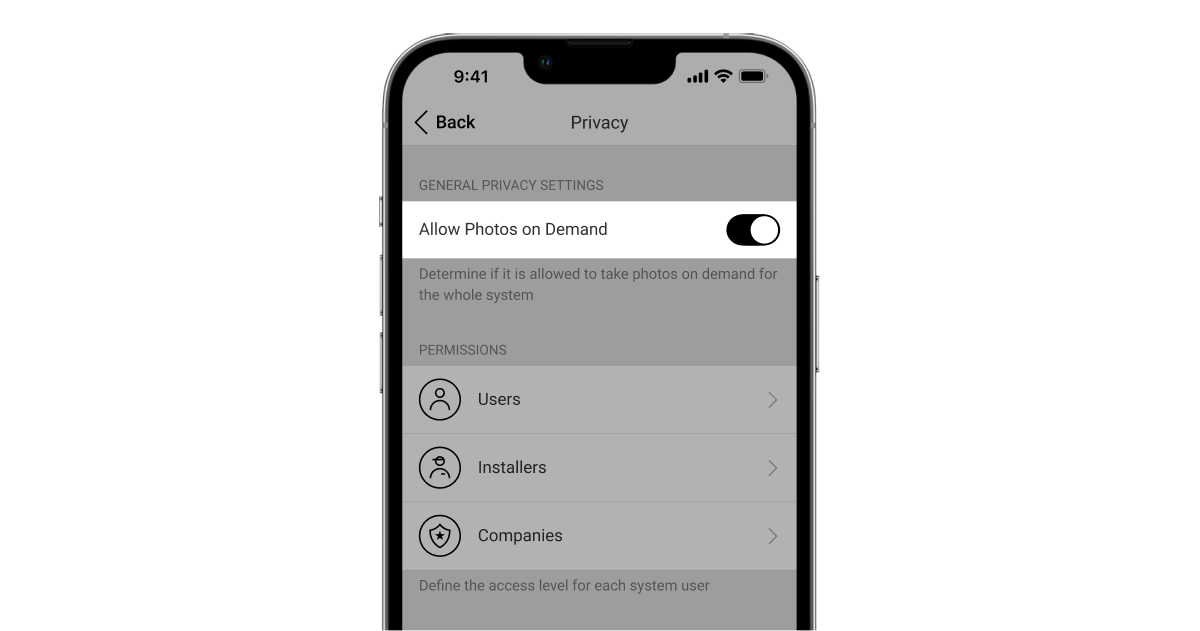
Um administrador de hub ou um utilizador com acesso às definições de privacidade pode ativar e configurar a funcionalidade Foto por pedido. O caminho para as configurações na app Ajax:
Dispositivos → Hub → Definições
→ Privacidade.
Este artigo fornece mais informações sobre como configurar o recurso Foto por pedido.
Configuração da funcionalidade Foto por cenário
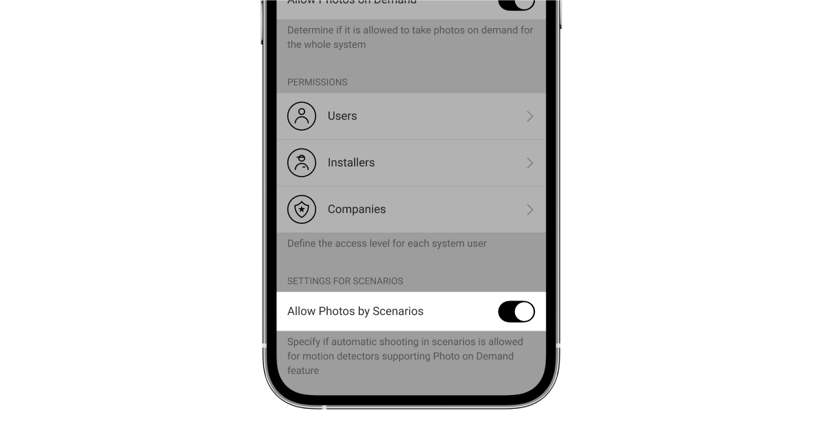
Um administrador do hub ou um utilizador com acesso às definições de privacidade pode ativar a funcionalidade Fotos por cenários. A forma de ativar a funcionalidade Foto por cenário na app Ajax:
Dispositivos → Hub → Definições
→ Privacidade → Permitir fotos por cenários.
Um administrador do hub ou um PRO com direitos de configuração do sistema pode criar e configurar um cenário. Para isso:
- Nas app Ajax, selecione a instalação se tiver várias.
- Aceda ao separador Dispositivos
e selecione um detetor com verificação fotográfica.
- Clique no ícone
para aceder às Definições do detetor.
- Selecione o menu Cenários na lista.
Este artigo fornece mais informações sobre a configuração da funcionalidade Foto por cenário.
Configure a funcionalidade Foto por programação
Um administrador do hub ou um PRO com direitos de configuração do sistema pode criar e configurar um cenário programado. Para isso:
- Abra a app Ajax e selecione a instalação se tiver várias ou se estiver a utilizar a app Ajax PRO.
- Aceda ao separador Dispositivos
e selecione um detetor com verificação fotográfica.
- Clique no ícone de engrenagem
para aceder às Definições do detetor.
- Selecione o menu Cenários na lista.
- Selecione o tipo de cenário Por programação.
- Especifique:
- Nome do cenário.
- Ação do dispositivo — por defeito, apenas Tirar foto. A quantidade de fotografias é igual à quantidade de Foto por pedido nas definições.
- Tempo de execução — formato 24h ou 12h, consoante o formato da hora do dispositivo. Clique no campo para definir a hora definida para o detetor.
- Repetir — clique no campo para definir o dia da semana.
- Quando o detetor pode tirar fotografias: sempre ou quando está armado. Por predefinição, o Superior MotionCam (PhOD) Fibra só tira fotografias por programação no modo armado.
Note que apenas o administrador do hub pode especificar quando o detetor tira fotografias.
- Clique em Guardar. O cenário aparecerá na lista de cenários do dispositivo.
Indicação
O indicador LED Superior MotionCam (PhOD) Fibra pode acender-se a vermelho ou verde, consoante o estado do detetor.
| Indicação | Evento | Nota |
| Acende-se a verde uma vez quando a alimentação é ligada. | O detetor está ligado. | |
| Acende-se a verde durante cerca de 1 segundo. | Alarme de movimento/alarme de tamper. | O dispositivo deteta movimento a cada 7 segundos. |
| Acende-se a verde durante 0,5 segundos. | Tira fotografias a pedido/por cenário. | Ao tirar uma foto por pedido ou por cenário, o indicador acende-se mesmo que a indicação LED esteja desligada nas definições do detetor. |
| Acende-se a verde durante alguns segundos. | Conexão do detetor ao hub. | |
| Em caso de alarme, acende-se lentamente a verde e apaga-se. | As baterias do detetor têm de ser substituídas. | |
| Pisca frequentemente a verde. | O detetor não está ligado ao hub. | |
| Acende-se a vermelho e pisca após a primeira ligação. | Erro de hardware. | O dispositivo precisa de ser reparado, contacte o Apoio Técnico Ajax. |
Avarias
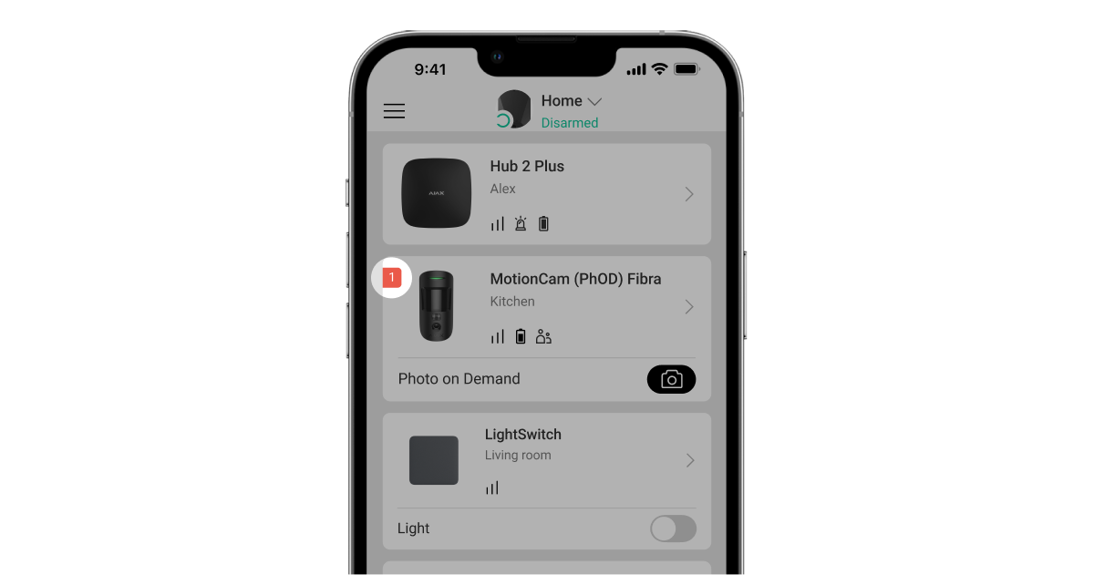
Quando o detetor deteta uma avaria (por exemplo, não há comunicação através do protocolo Fibra), é apresentado um contador de avarias na app Ajax, no canto superior esquerdo do ícone do dispositivo.
Todas as avarias podem ser vistas nos estados do dispositivo. Os campos com avarias vão ser indicados com vermelho.
Uma avaria é apresentada se:
- A temperatura do dispositivo está fora dos limites aceitáveis.
- A carcaça do detetor está aberta (o tamper é ativado).
- Não há sinal através de protocolo Fibra.
- A bateria do detetor está fraca.
Manutenção
Verifique regularmente o funcionamento do dispositivo. Limpe a carcaça do dispositivo do pó, teias de aranha e outros contaminantes à medida que vão surgindo. Utilize um pano seco e macio adequado para a manutenção do equipamento.
Não utilize quaisquer substâncias que contenham álcool, acetona, gasolina e outros solventes ativos para limpar o detetor. Limpe suavemente a lente do detetor e a câmara: os riscos podem provocar uma diminuição da sensibilidade do detetor, imagens de má qualidade e avarias na câmara.
Especificações técnicas
Conjunto completo
- Superior MotionCam (PhOD) Fibra.
- Painel de instalação SmartBracket.
- Kit de instalação.
- Guia Rápido.
Garantia
A garantia dos produtos da empresa de responsabilidade limitada “Ajax Systems Manufacturing” é válida durante 2 anos após a compra.
Se o dispositivo não funcionar corretamente, contacte primeiro o Apoio Técnico Ajax. Em maioria dos casos, os problemas técnicos podem ser resolvidos remotamente.
Contactar o Apoio Técnico:
