Cloud Signaling is a service to establish communication between Ajax systems and third-party monitoring software. Acting as a link between a hub and monitoring stations, Cloud Signaling converts the notifications received from the hub into event protocol supported by the Central Monitoring Station’s (CMS) software.
Cloud Signaling provides the ability to deliver events to the CMS directly from Ajax Cloud. The service is integrated into the PRO Desktop app. Alarm monitoring companies or companies that simultaneously install security systems and respond to their alarms and events can use PRO Desktop to set up and connect security systems. And security or monitoring companies can use the app to organize a CMS.
How Cloud Signaling works
All data transmitted by an Ajax system is protected by block encryption with a dynamic key. Third-party CMS software cannot decrypt it independently. Cloud Signaling receives a message from an Ajax system, decrypts it, and converts it into standardized protocol messages. The service translates it into CMS software without installing any Ajax products on the Security company’s premises.
Only the SIA DC-09 protocol is available.
The SIA DC-09 (SIA-DCS/ADM-CID) message can transmit additional information, such as web links, geographic coordinates, or other standardized data. The SIA DC-09 (SIA-DCS/ADM-CID) protocol can transfer photos from MotionCam/MotionCam Outdoor motion sensors and user coordinates to the monitoring station when the panic button is pressed in Ajax app.
| SIA DC-09 (SIA-DCS/ADM-CID) message template: <LF><crc><0LLL><“id”><seq><Rrcvr> <Lpref> <#acct> [<pad> | … data …] [x… data…] <timestamp> < CR> |
|
| <LF> | Message beginning marker in ASCII, transmitted in binary value 0x0A. |
| <crc> | Checksum to check the integrity of the message, transmitted as four characters in ASCII. |
| <0LLL> | The message length, where the first character is always 0, and the next three are hex characters in ASCII. |
| <“id”> | Protocol type indicator. One of two values is used depending on “Format” field value:
|
| <seq> | The sequence number of the sent message. The range is 0001-9999, after which counting starts over from 0001. |
| <Rrcvr> | Receiver number — not used. |
| <Lpref> | Account number prefix. Constant value is L0. |
| <#acct> | Account number. The # character followed by 3 to 16 hex characters in ASCII. |
| [<pad>|…data…] |
Alarm data. In the beginning, the # character and account number are indicated, then the separator “|”, followed by a message. If SIA-DCS format is used: The “N” constant indicates a new event, followed by the “ri” constant and the group number. Next, the “/” symbol indicates SIA event code, which consists of two Latin letters and a zone number. Example (Intrusion alarm from Device 1 in Group 2 for an Account number 1234): [#1234|Nri2/BA1] If ADM-CID format is used: The first digit is 1 (Alarm) or 3 (Restore), a three-digit event code by the Contact ID protocol, a group number, and a zone number. Example (Intrusion alarm from Device 1 in Group 2 for an Account number 1234): [#1234|1130 02 001] The message after the separator can contain from 3 to 16 hex characters in ASCII. |
| [x…data…] |
Additional data, which may contain photo confirmation from MotionCam/MotionCam Outdoor detectors or the location of the device on which the user pressed the panic button in Ajax app. Photo confirmation is sent as a web link, at the beginning of which the data type is indicated — the V character (Verification). When the Transfer device or group name to CMS events toggle is enabled, the device or user name is sent with the data type of “I” (Alarm Text), and the group name is sent with the data type of “L” (Location). Coordinates are transmitted in the format [X30E28.0] [Y50N29.6], where |
| <timestamp> | Timestamp. |
| <CR> |
End of message marker in ASCII, transmitted in binary value 0x0D. |
Please note that the series of photos is transmitted as a separate event. The photos will be available immediately after they are transferred to Ajax Cloud server. The links to the photos will remain valid for 7 days from the moment they are transmitted to the security company’s monitoring station.
The link to one photo can contain up to 425 symbols.
Sample of an event with two photos:
| CB640375″ADM-CID”0086L0#1234[#1234|1130 02 001][Vhttps://ajax-sample.com/first_photo.jpg,https://ajax-sample.com/second_photo.jpg]_16:43:06,10-07-2020 |
Adding the receiver
There are two roles available to use Cloud Signaling: Senior CMS Engineer and CMS Engineer. Only the Senior CMS Engineer has the right to add, update, and delete the receiver.
To add the receiver, in PRO Desktop:
- Sign in to a PRO account.
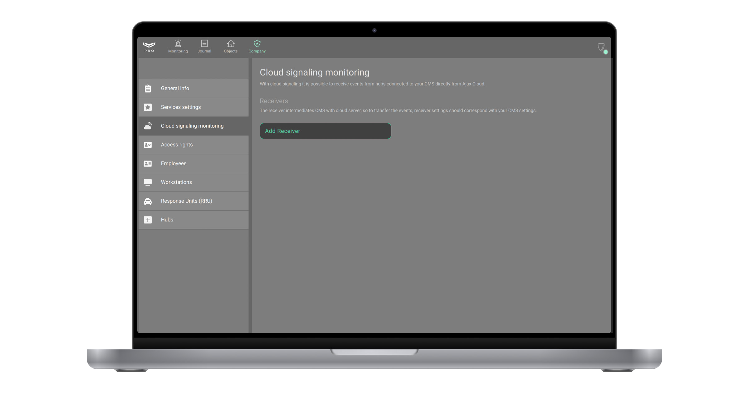
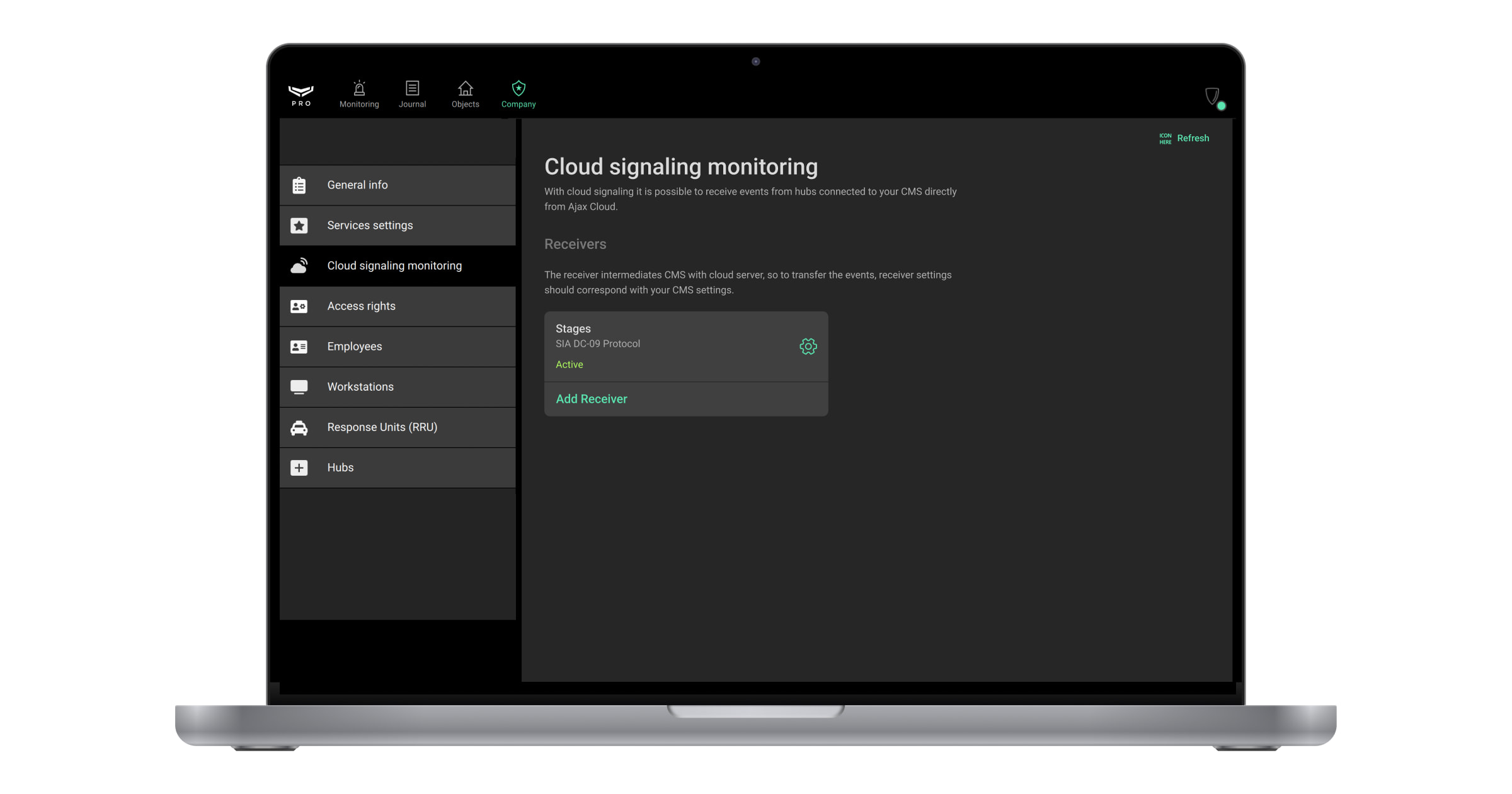
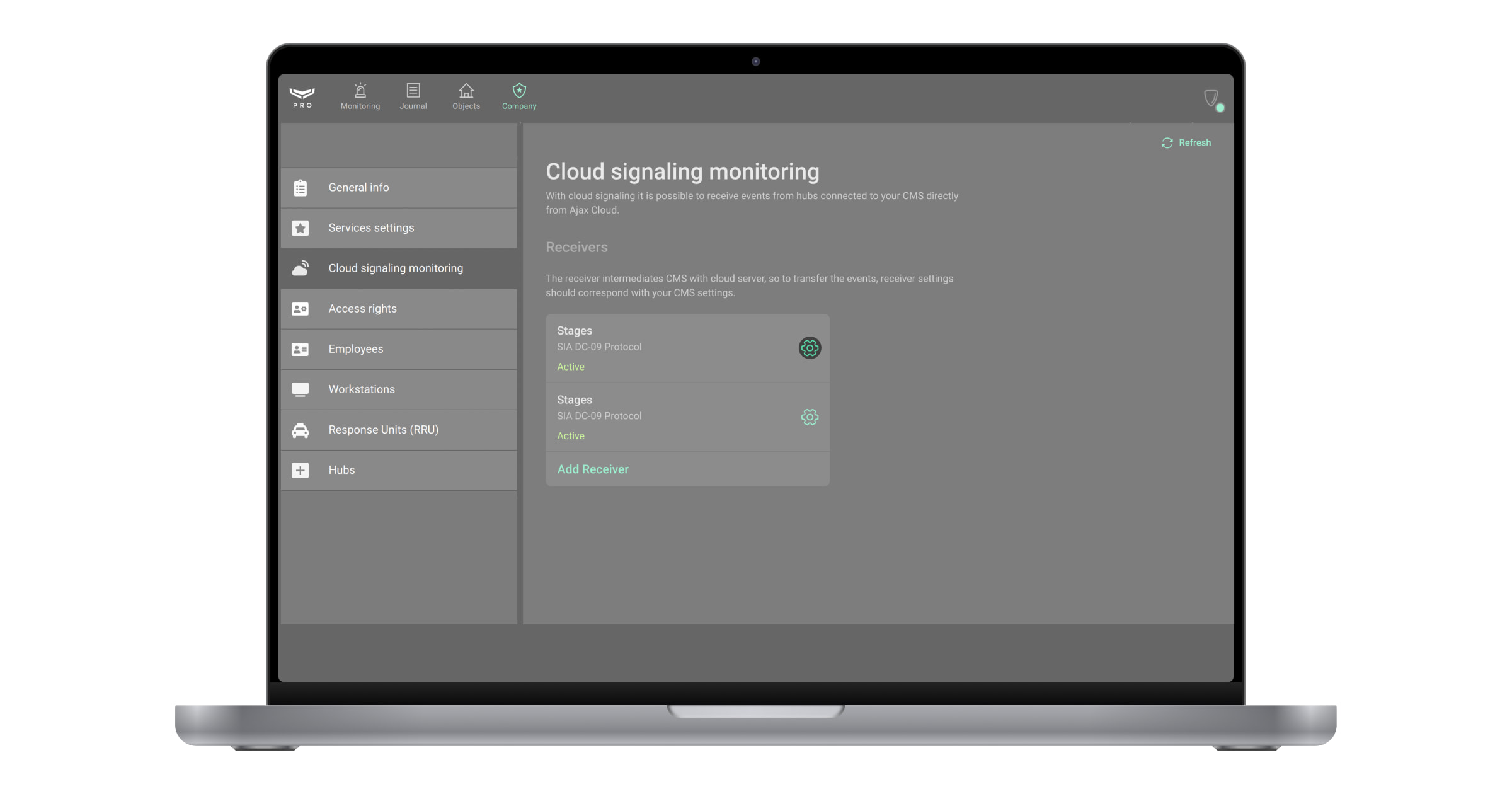
- Open the Company module.
- Click on the Cloud signaling monitoring menu. It contains information about receivers that intermediate CMS with the cloud server. The user can add, delete, or change receiver details.
- Click the Add Receiver button.

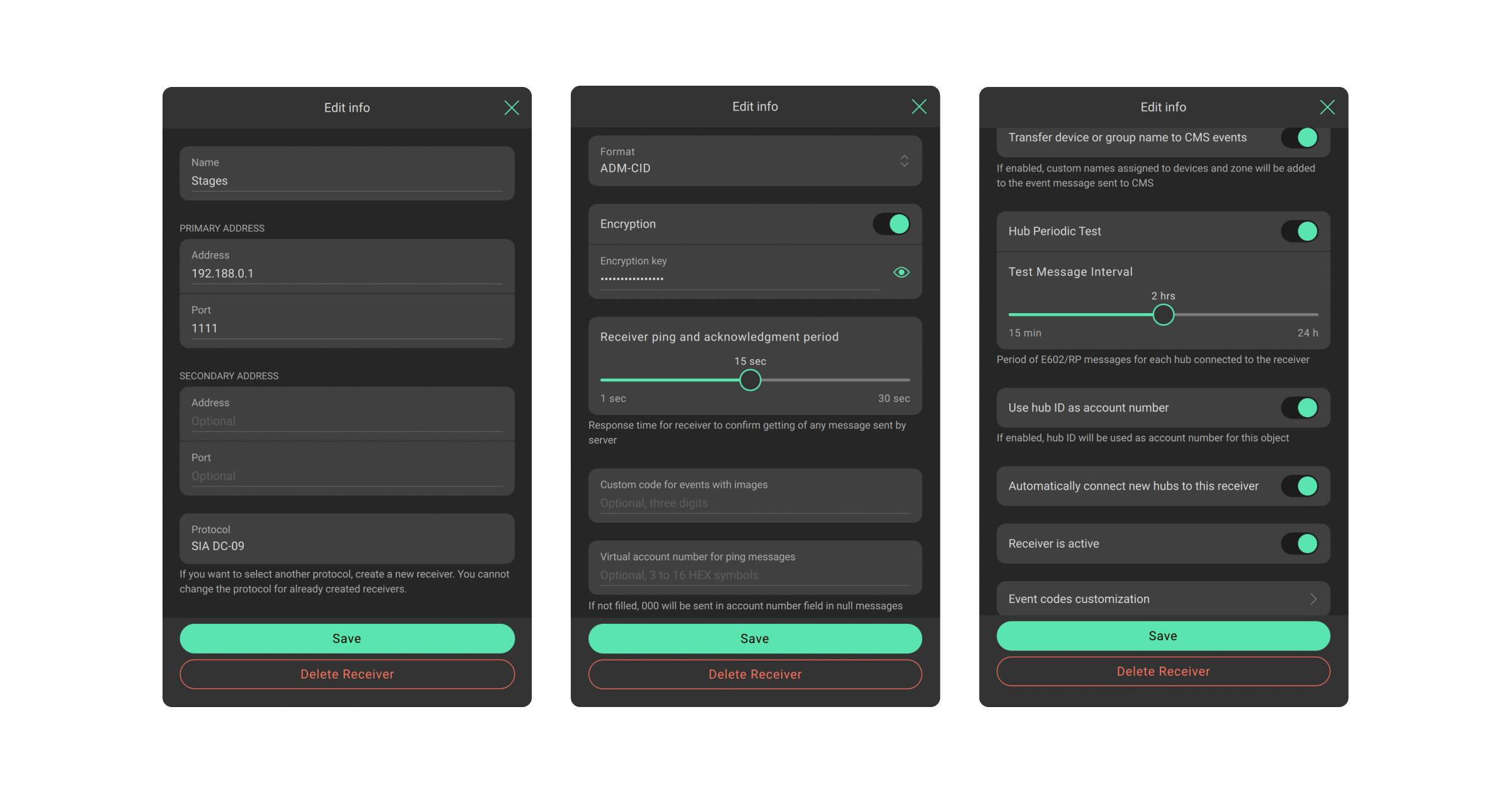
- Specify the receiver name, the primary address (IP or DNS) and its port, the secondary address and its port (optional).
- Specify the protocol format: ADM-CID or SIA-DCS.
- If the Encryption toggle is enabled, specify Encryption Key.
- Specify Custom code for events with images (optional) — a Contact ID code that can replace the standard code for messages containing MotionCam images.
- Click Save.
Cloud Signaling always expects message receipt confirmation from CMS. If Cloud Signaling does not receive confirmation, it reports the loss of connection with the CMS.
The range for the Receiver ping and acknowledgement period spans from 1 to 30 seconds. Specify the Virtual account number for ping messages. If this setting is not configured, the “000” text will be sent in the account number field in null messages instead.
| SIA DC-09 ping message template: <LF><crc><0LLL><“NULL”><seq><Rrcvr><Lpref><#acct><timestamp><CR> |
|
| <LF> | Message beginning marker in ASCII, transmitted as the binary value 0x0A. |
| <crc> | Checksum to verify the integrity of the message, transmitted as four characters in ASCII. |
| <0LLL> | The message length, where the first character is always 0, followed by the next three hex characters in ASCII. |
| <“NULL”> | “NULL” constant. |
| <seq> | The sequence number of the sent message, ranging from 0001 to 9999. After reaching 9999, the count resets to 0001. |
| <Rrcvr> | Receiver number — not used. |
| <Lpref> | Account number prefix. The constant value is L0. |
| <#acct> | Virtual account number for ping messages. If not set, the “000” text will replace the account number field in null messages. |
| <timestamp> | Timestamp. |
| <CR> |
Message ending marker in ASCII, transmitted as the binary value 0x0D. |
If the Transfer device or group name to CMS events toggle is enabled, custom names assigned to devices and zones will be added to the event message sent to the CMS.
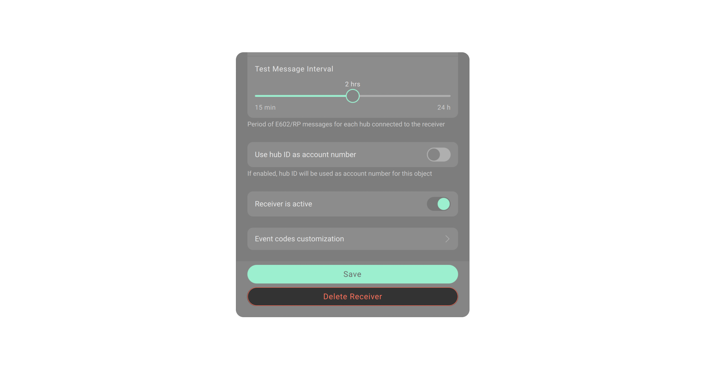
The Hub Periodic Test toggle allows disabling periodic test messages that are used to verify hub connection. Cloud Signaling sends these messages to the CMS under code E602, meaning the hub is connected.
The range of the Test Message Interval is from 15 minutes to 24 hours.
If you disable these regular test messages, the hub will continue to report the connection status at predetermined intervals. However, Cloud Signaling will only notify the CMS if the hub connection is lost. In this case, the program sends a single event to the CMS under code E350, and waits until the connection is restored. Once the hub connection is restored, Cloud Signaling transmits an event under code R350 to the CMS.
Enable the following toggle to use the hub ID as the account number for the object you’re adding:
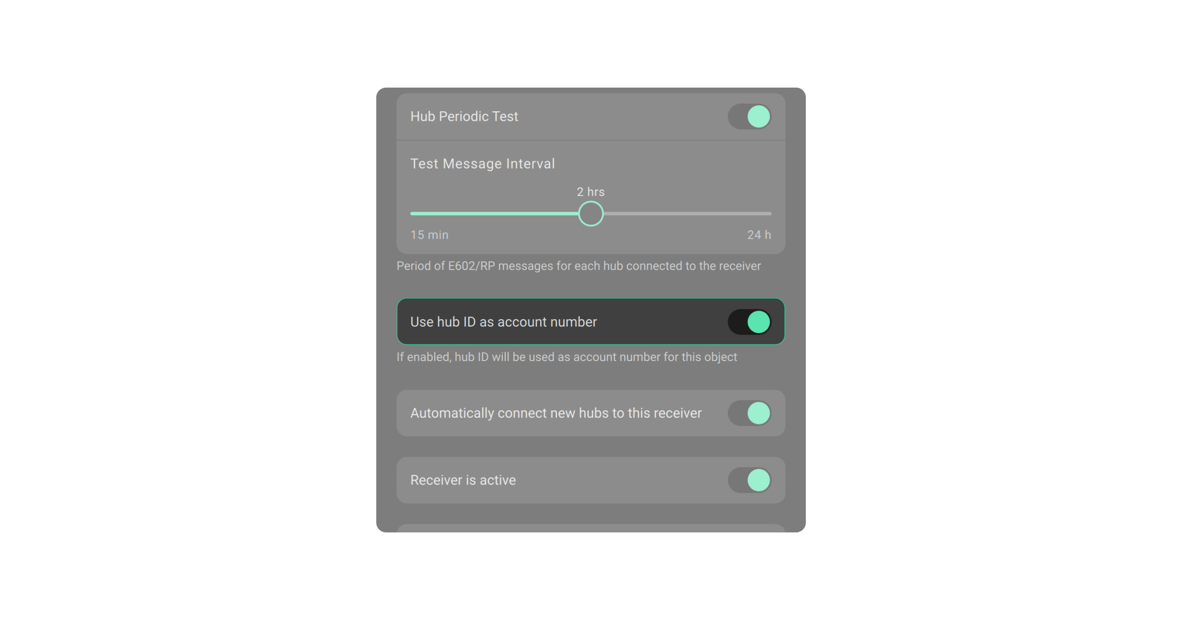
If the Automatically connect new hubs to this receiver toggle is enabled, the request to add the new hub will be immediately approved. The function is only available when the Use hub ID as account number toggle is also enabled.
To deactivate the receiver — disable the Receiver is active toggle. The Disabled connection state is now displayed on the receiver’s list. The receiver’s settings are saved, but the connection to the CMS is lost.
The Event codes customization settings allow changing codes received by the CMS from Ajax hubs. The monitoring company changes the defined CID/SIA-DCS codes by itself.
The feature is available in PRO Desktop version 3.9 or higher.
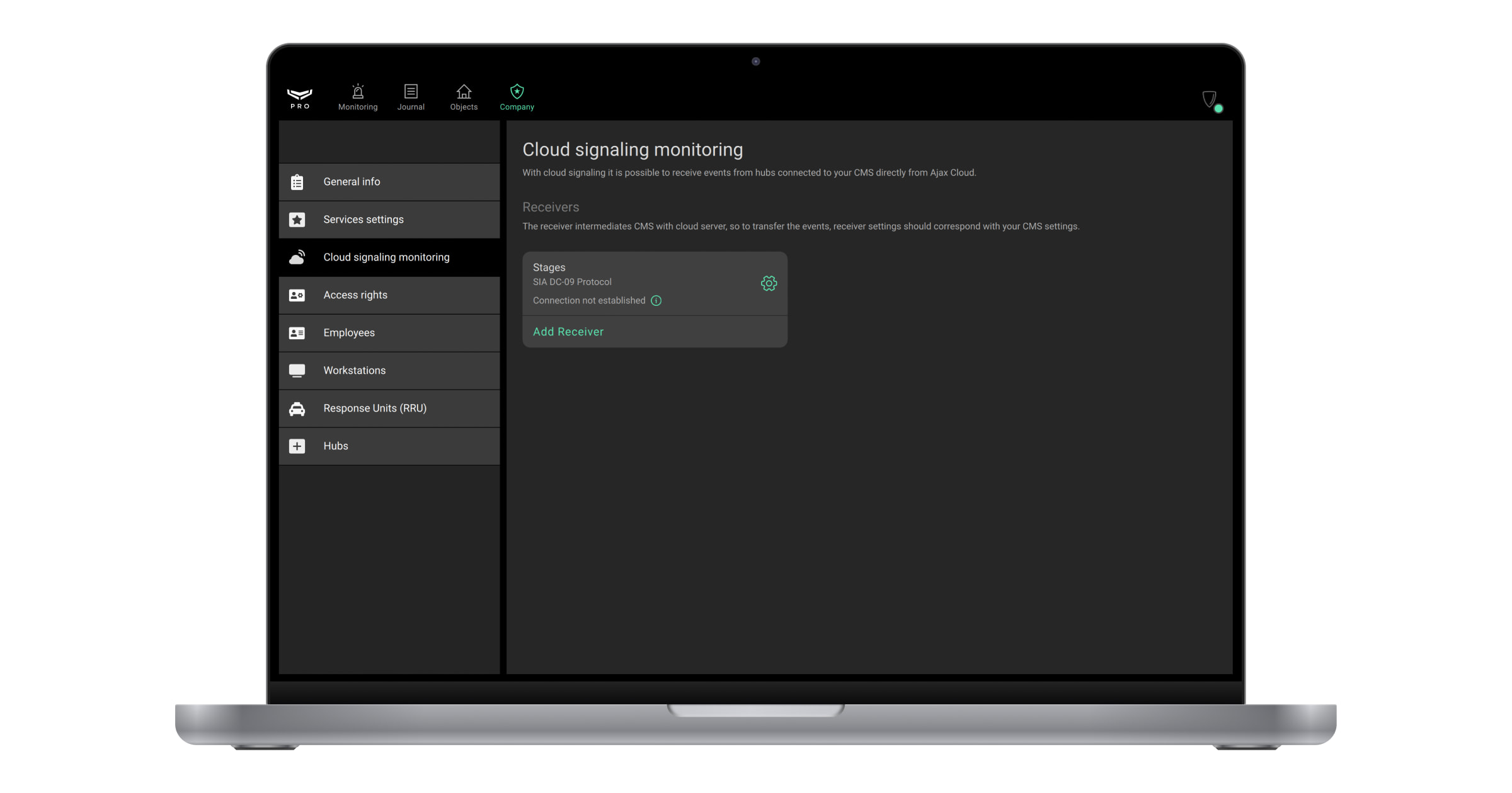
When the receiver is added, its name, protocol, and connection state are displayed on the Cloud signaling monitoring menu.
The user can add 10 receivers and delete the previously added ones.
In the app, you can see one of the following states of connection to the CMS:
- Disabled — the receiver is disabled.
- Active — the receiver is connected to the CMS.
- Only primary address available — the receiver is connected to the CMS only by primary address (secondary is unreachable).
- Only secondary address available — the receiver is connected to the CMS only by secondary address (primary is unreachable).
- Connection not established — the receiver is enabled but waiting for the first event from the hub.
- Connection lost — the receiver is unable to connect to the CMS.
The server—receiver connection is established when at least one event is sent from the hub to the receiver.
Mapping of the hub to the receiver
The Senior CMS Engineer and the CMS Engineer have the right to create, update and view the mapping of the hub to the receiver. The Head of operators and the Operator can only view the mapping of the hub to the receiver.
To do this:
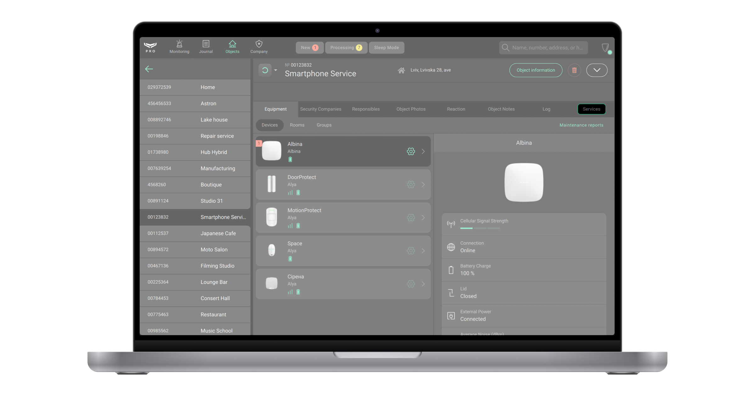
- Select the Objects module from the list of modules in the upper left corner of the screen.
- Select the object you want to map to the receiver.
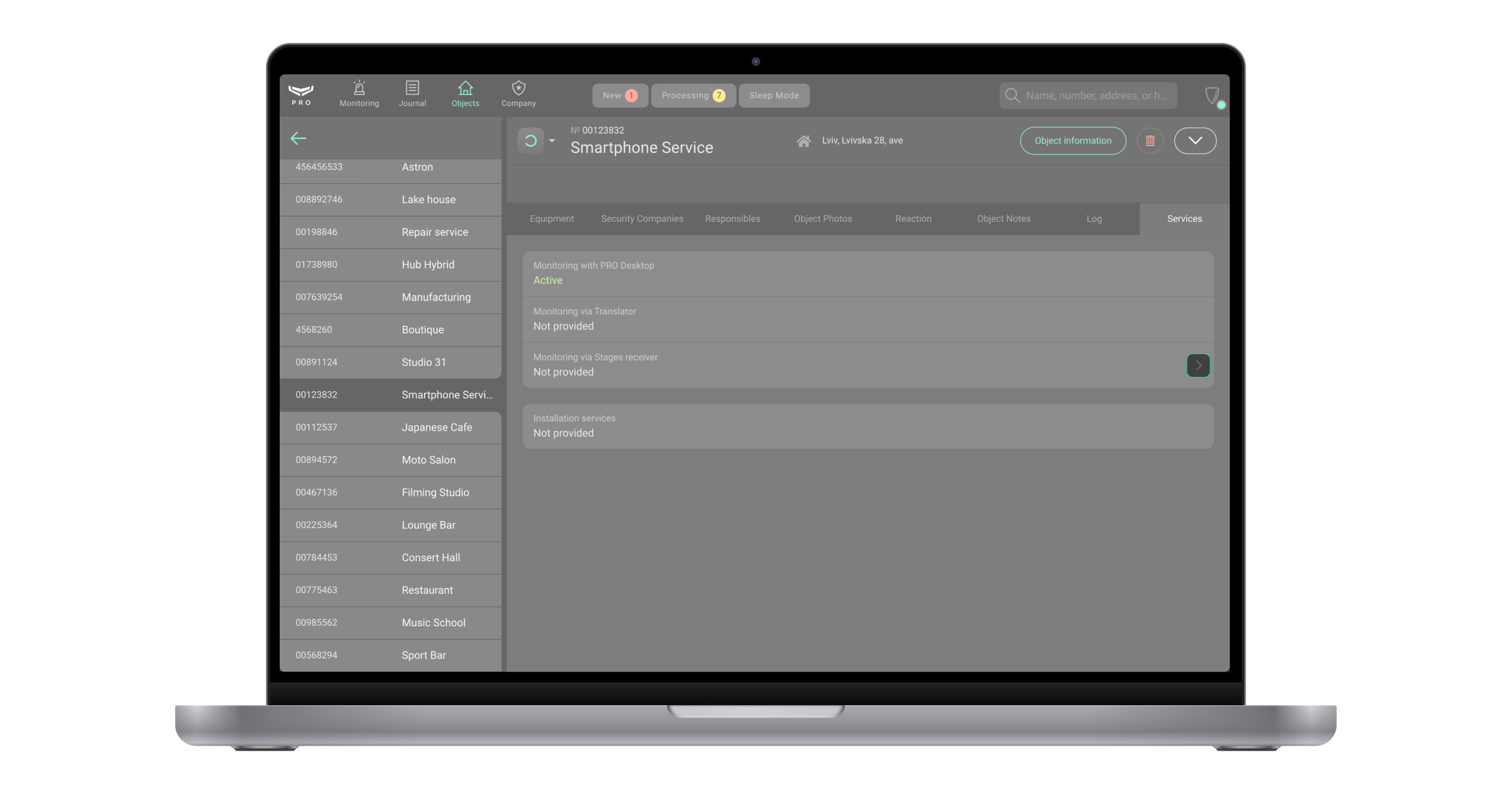
- Click the Maintenance to view monitoring states.
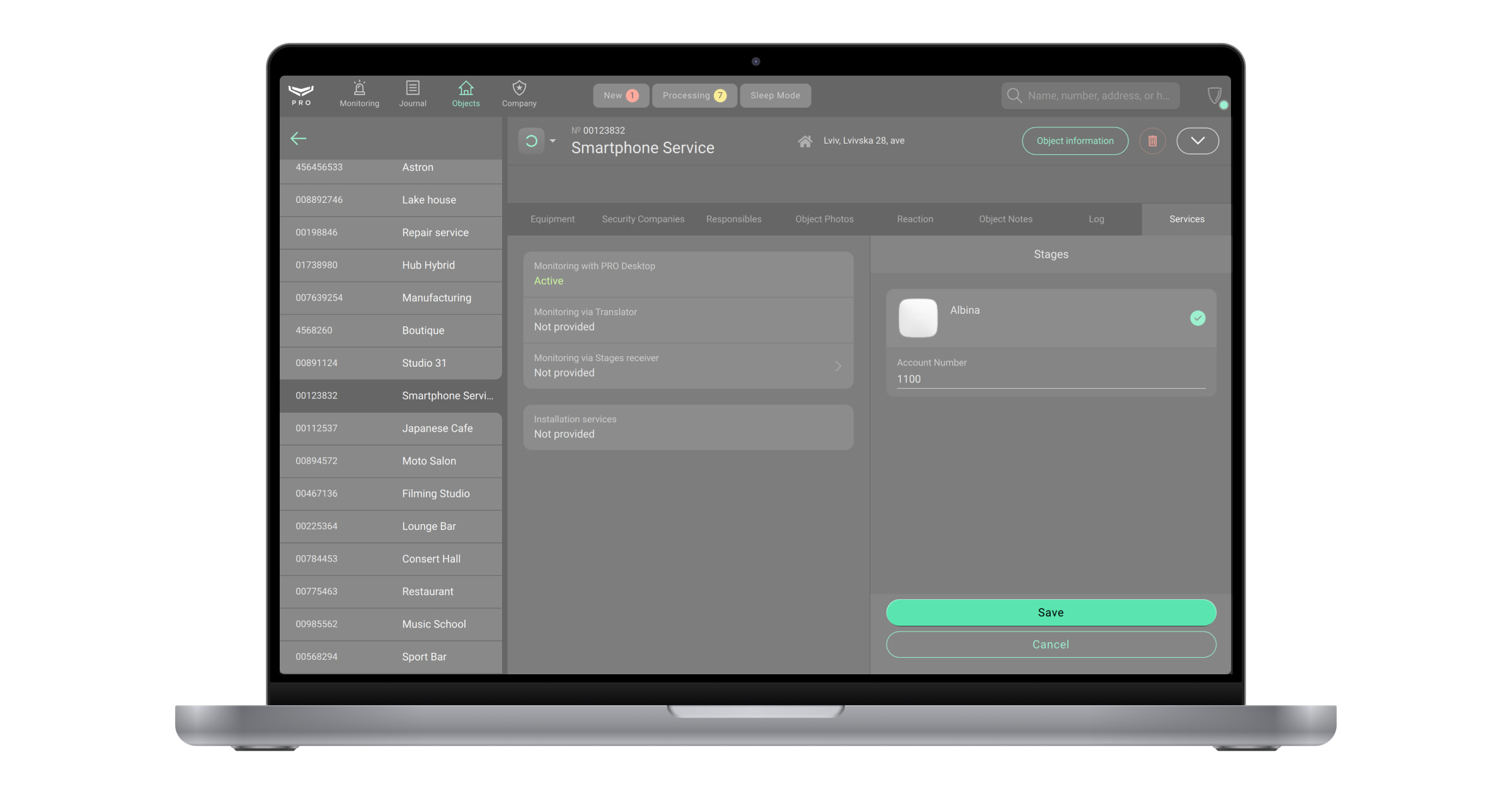
- Click the Monitoring via <Name> receiver button.
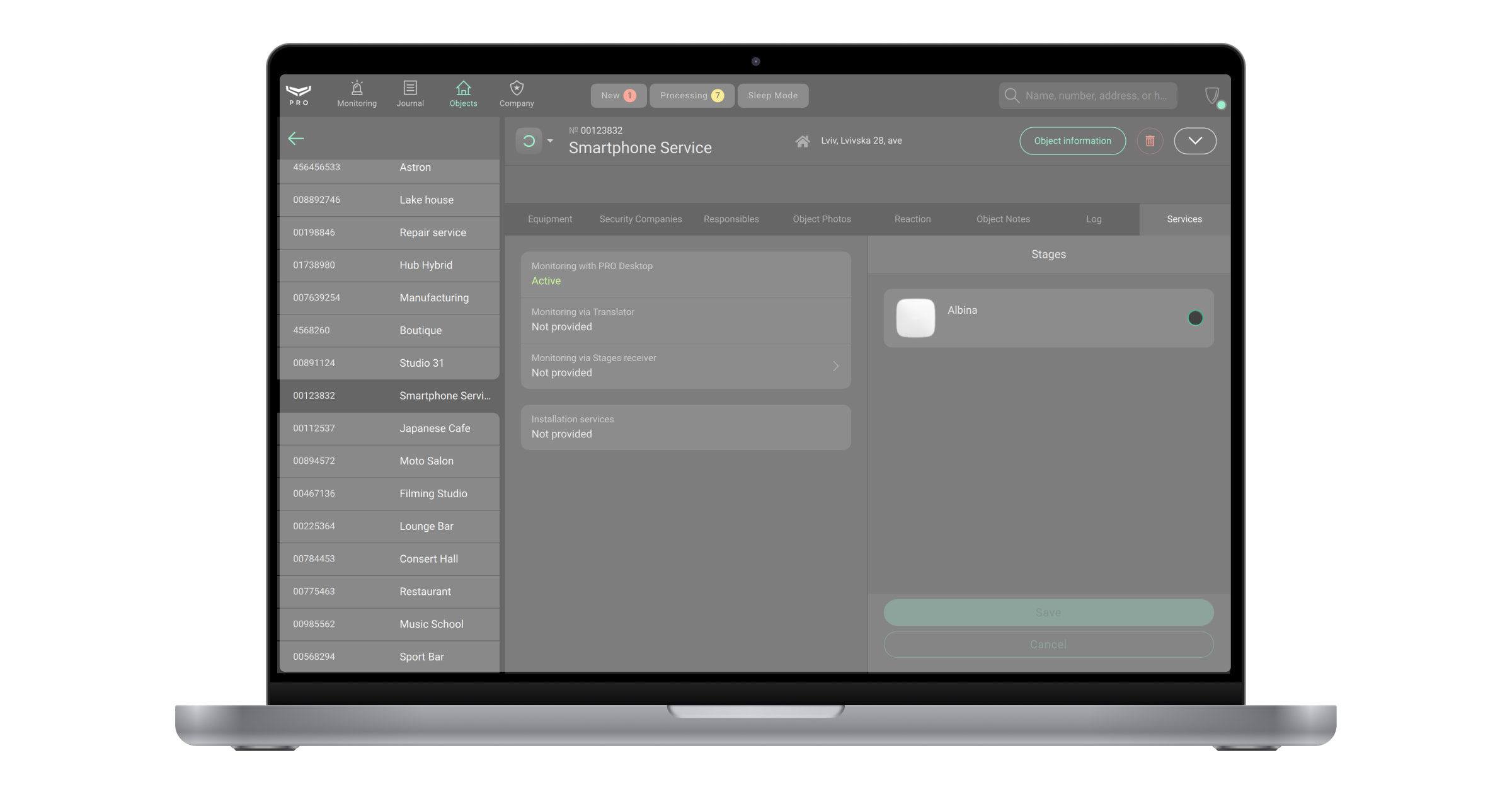
- Select the hub you want to map to the receiver.
- Specify the Account number which is used for messages sent to the receiver. This is not the account number from the PRO Desktop app, but it may be the same. All hubs mapped to one receiver have a unique account number.
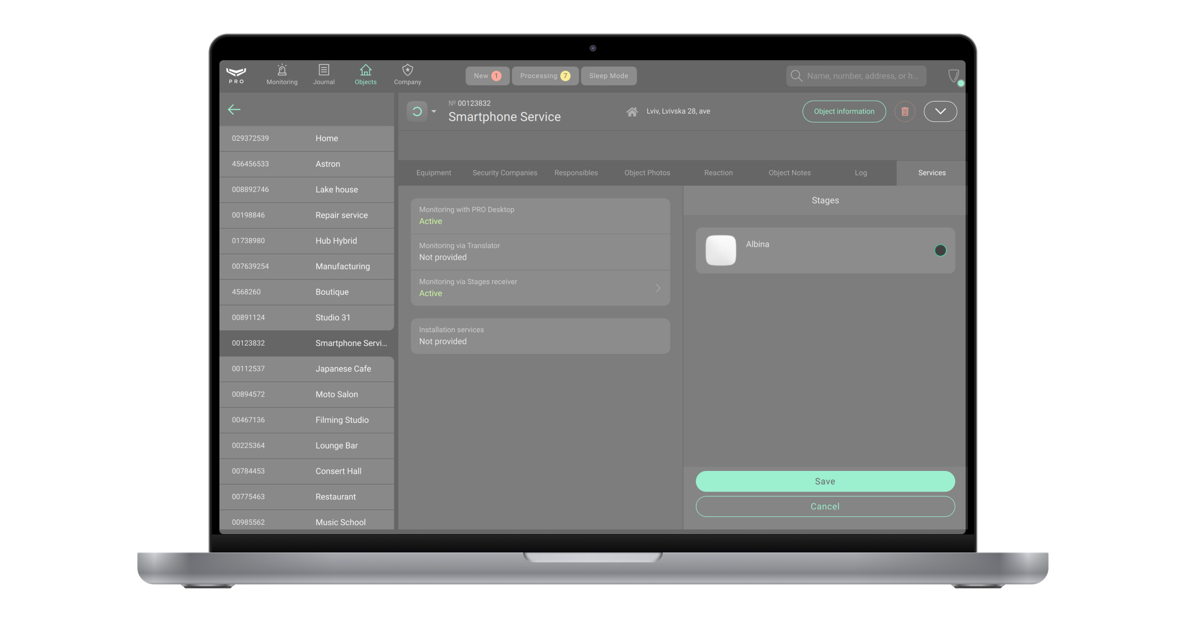
- Click Save. After that, the state Monitoring via <Name> receiver will be changed from Not provided to Active.
With the Ajax PRO Desktop 4.0 firmware version and higher, it’s available to activate/deactivate the Monitoring with PRO Desktop channel for any monitoring company.
Delete mapping of the hub to the receiver
The Senior CMS Engineer and the CMS Engineer have the right to delete the hub mapping.
To do this:
- Select the Objects module from the list of modules in the upper left corner of the screen.
- Select the object you no longer want to map to the receiver.
- Click Maintenance to view monitoring states.
- Click the Monitoring via <Name> receiver button.
- Select the hub you no longer want to map to the receiver.
- Click Save.
- Click the Stop monitoring button on the pop-up window. After that, the state Monitoring via <Name> receiver will be changed from Active to Not provided.
Receiver events
Access to the Journal module has Company owner, CMS Engineer, Senior CMS Engineer, Head of operators, Operator, Installer, and Head of installers.
To view the receiver events:
- Select the Journal module from the list of modules in the upper left corner of the screen.
- Select the object.
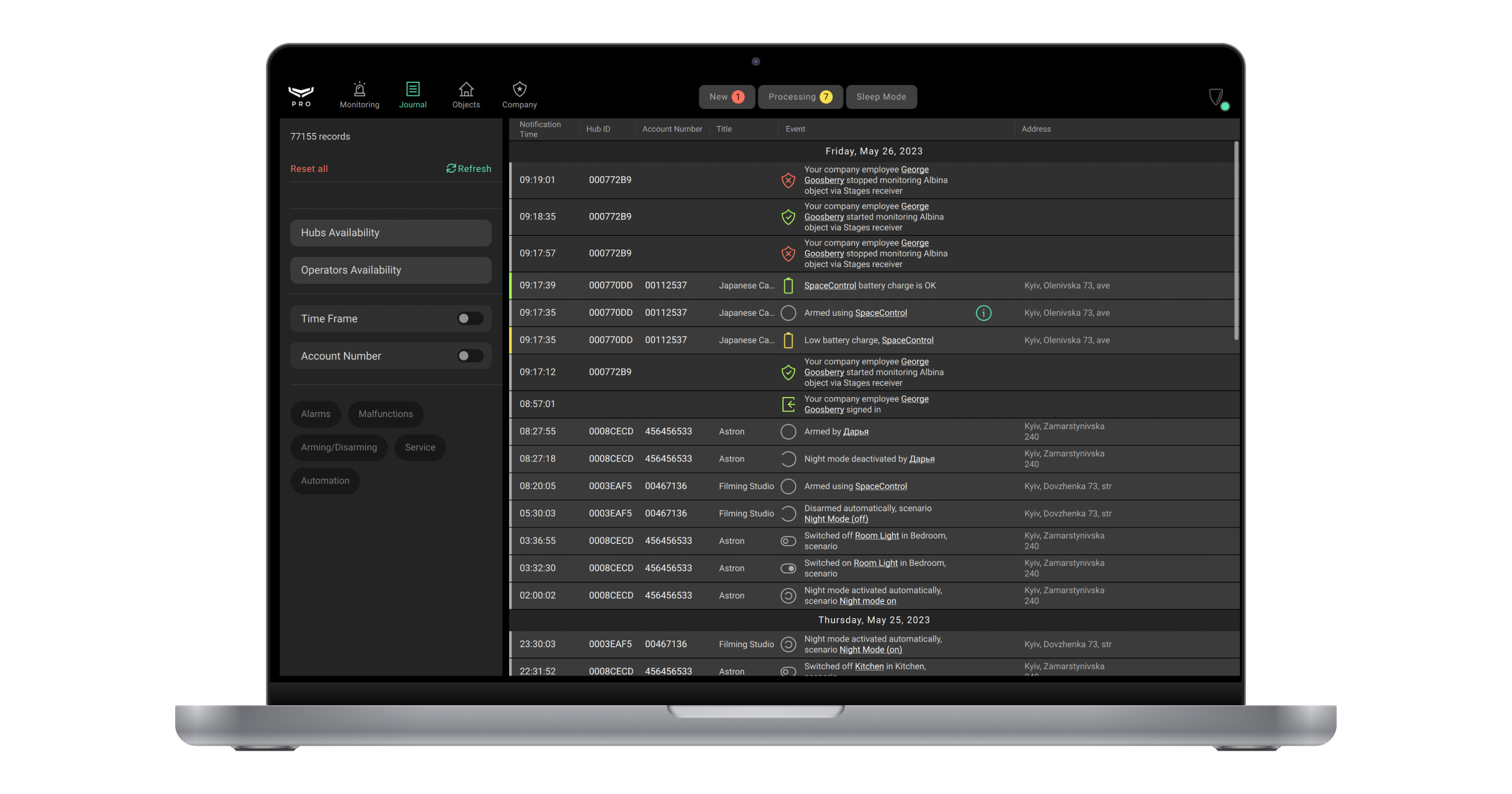
A list of receiver events will be displayed in the Journal module:
- Your company employee added new receiver for cloud signaling monitoring.
- Your company employee changed settings for receiver.
- Your company employee deleted receiver.
- Receiver lost connection via primary/secondary address.
- Restored receiver connection via primary/secondary address.
- Your company employee started monitoring object via receiver.
- Your company employee updated account number of object for receiver.
- Your company employee stopped monitoring object via receiver.
Set and apply the range to filter events by time. To generate a report based on the specified parameters, click the report generation button next to the filter name.
Deleting the receiver
Only Senior CMS Engineer has the right to delete the receiver.
To delete the receiver, in PRO Desktop:
- Open the Company module.
- Click on the Cloud signaling monitoring menu.
- Click the button.
- Click the Delete Receiver button.
- Click the Delete button on the pop-up window. When the receiver is deleted, all its settings are erased, and all connected hubs stop sending their events to the corresponding CMS.
The receiver cannot be deleted if at least one hub is mapped to that receiver. You should previously delete mapping of all hubs to the receiver.