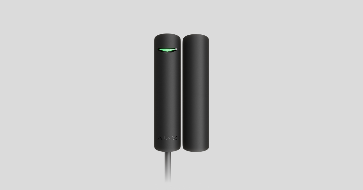
DoorProtect Plus Fibra is a wired bus opening, shock, and tilt detector. Designed for indoor use. Supports connection of a third-party normally closed detector.
The detector is compatible with Hub Hybrid (2G) and Hub Hybrid (4G). Connection to other hubs, radio signal range extenders, ocBridge Plus, and uartBridge is not provided. Integration with other security systems is also not provided.
DoorProtect Plus Fibra only works as a part of the Ajax system, communicating with the hub via the secure Fibra protocol. The wired connection range is up to 2,000 meters when connected via twisted pair U/UTP cat.5.
DoorProtect Plus Fibra is the device of the new Fibra wired product line. Such devices can only be purchased, installed and administered by accredited Ajax partners.
Functional elements
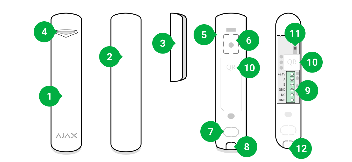
- DoorProtect Plus Fibra opening, shock, and tilt detector.
- Large magnet. Acts up to 2 cm away from the detector.
- Small magnet. Acts up to 1 cm away from the detector.
- LED indicator.
- Rear panel of the detector body. Used as a mount.
- Perforated part of the mounting plate. It is necessary to trigger a tamper in an attempt to detach the detector from the surface. Do not break it off.
- Perforated part for routing wires through the wall.
- Perforated part for routing wires at the bottom of the detector.
- Terminal block for detector connection.
- QR code with the device ID. Used to connect to the Ajax system.
- Tamper button.
- Hole for attaching the mounting panel with a screw.
Operating principle
DoorProtect Plus Fibra is a wired opening, shock, and tilt detector. It connects to the hub via a metallic bus and uses Fibra protocol.
The detector responds to alarms of three types: opening, shock, and tilt.
The detector can be positioned horizontally. If there is no need to detect the opening of doors or windows, use only the detector part (without magnets) and disable the magnetic sensor in the settings.
If triggered, armed DoorProtect Plus Fibra transmits the alarm signal to the hub within 0.15 seconds, activates the sirens connected to the hub, and notifies the user and the security company.
Users know exactly where an alarm is detected. Notifications state the name of the hub (the name of the guarded facility), the name of the device, and the virtual room to which the detector is assigned.
Opening detection
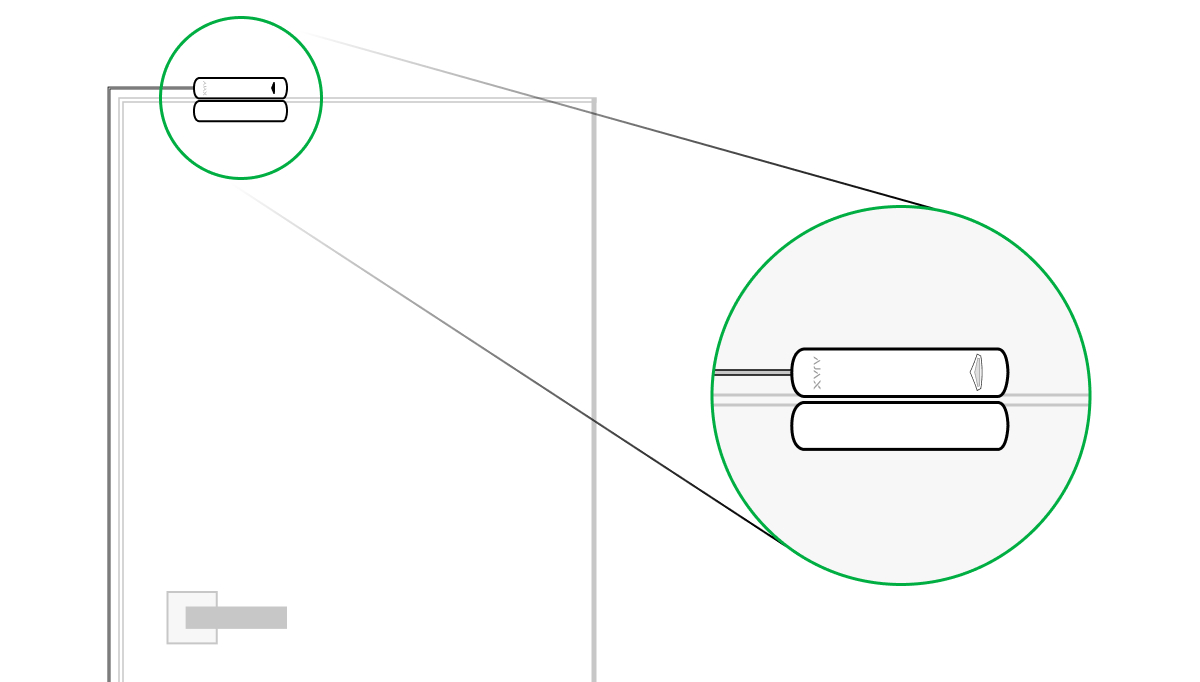
The detector registers the opening of doors or windows with a reed switch. If installed using a standard method, the detector consists of two parts: the detector and the magnet. The detector part is mounted on a frame/fixed element of a structure, while the magnet part is attached to a moving wing/sliding part.
The sensitive element of the detector is a reed switch (sealed contact). This is a small flask with an open contact group inside. When a magnet is brought to the detector, a magnetic field is generated and the detector contacts are magnetized, attracted, and closed. Opening the flap or door moves the magnet away from the reed switch, which opens the circuit, and the detector detects opening.
It takes a single magnet for the DoorProtect Plus Fibra detector to create a magnetic field. Use a small or large magnet depending on the conditions at the installation site.
DoorProtect Plus Fibra has two reed switches, which allows you to install a magnet on both the left and right side of the detector. Note that DoorProtect Plus Fibra works with one magnet on one side only. If magnets are installed on both sides, the detector will not detect the opening correctly.
A small magnet acts at up to 1 cm, and a large magnet up to 2 cm.
Shock detection
To detect shock and vibration, the detector is equipped with a built-in accelerometer. It responds to attempted burglary, e.g. an attempt to break down a door/window or drill through a door lock.
Tilt change detection
You can attach DoorProtect Plus Fibra to windows, including skylights, and arm the system when the window is in the ventilation mode (be sure to deactivate the magnetic detector in the settings before you do this). To detect changes in the door or window position, attach the detector to a moving wing.
For additional protection, the detector features a built-in accelerometer. The detector uses it to notify the user if an intruder attempts to open or break through a window that was opened for ventilation. The tilt sensor detects vertical deflection of the device of more than 5°.
Fibra data transfer protocol
The detector uses Fibra technology to transmit alarms and events. This is a two-way wired data transfer protocol that provides fast and reliable communication between the hub and other devices within the system. Fibra uses the bus connection method to immediately transmit data from the system, even if it comprises 100 devices.
Fibra supports block encryption with a floating key and device authentication at every communication session to prevent sabotage and device spoofing. The protocol provides for regular polls of detectors by the hub at intervals of 12 to 300 seconds to monitor communication with all devices and display their statuses in real-time in Ajax apps.
Connecting a third-party wired detector
You can connect an external wired NC (normally closed) detector to DoorProtect Plus Fibra. This can be any detector: motion, opening, or vibration.
DoorProtect Plus Fibra cannot power a third-party detector. It should be connected separately. For the type and voltage of the third-party detector, refer to the device documentation or contact the manufacturer’s technical support.
Sending events to the monitoring station
The Ajax system can transmit alarms to the PRO Desktop monitoring app as well as the central monitoring station (CMS) as a SurGard (Contact ID), ADEMCO 685, SIA DC-09 (ADM-CID), and other proprietary protocols. A complete list of supported protocols is available here.
Types of DoorProtect Plus Fibra events to be transmitted to PRO Desktop and CMS:
- Primary detector alarm.
- External NC detector alarm.
- Tamper alarm/recovery.
- Hub connection loss/restoration.
- Turning DoorProtect Plus Fibra off/on.
- Unsuccessful attempt to arm the security system (with Integrity Check enabled).
When an alarm is received, the operator of the security company knows exactly what happened and where to send the fast response team. Address capacity of Ajax devices allows you to send not only events, but also the type of the device, its assigned name, and the room of its location to the PRO Desktop/CMS (the list of transmitted parameters may differ depending on the type of the CMS and the protocol selected for communication with the CMS).
The device ID, the loop (zone) number, and the bus number can be found in its states in the Ajax app.
Selection of the installation site for the detector
When choosing where to place the detector, consider the parameters that affect its normal operation: Fibra signal strength, length of the cable for connecting the detector, and the opening detection zone.
Consider the placement recommendations when designing your facility’s security system. Design and installation of the security system should be carried out by professionals. A list of authorized official Ajax partners is available here.
Design and preparation
For the system to work correctly, it is important to properly design the project and install all devices correctly. Failure to follow the basic installation rules and recommendations of this manual may result in detector malfunction, false alarms, or loss of connection with already installed devices.
When designing the layout scheme of the detectors, consider the wiring diagram of the power cables laid on the site. Signal cables must be laid at a distance of at least 50 cm from the power cables when lying parallel, and, if they intersect, it must be at a 90° angle. Note that if you connect multiple devices on the same bus, detectors are connected in sequence.
The maximum number of connectable devices for the Hub Hybrid is 100 at the default settings.
For facilities that are under construction or renovation, cables are laid after the main wiring of the facility. Use protective tubes to organize and secure the cables; ties, clips, and staples can be used to anchor them.
When laying cables externally (without mounting them inside the walls), use an electric channel raceway. Raceways should be no more than half-filled with cables. Do not allow cables to sag. The raceway should be hidden from view if possible — for example, behind furniture.
We recommend laying cables inside walls, floors, and ceilings. This will provide greater security; the cables will not be visible, and it will be impossible for an intruder to access them.
When selecting a cable, consider the length of the connection lines and the number of detectors to be connected; these parameters affect the signal strength. We recommend using shielded copper cables with a high-quality insulation layer.
When installing, observe the bend radius that the manufacturer specifies in the cable specs. Otherwise, you risk damaging or breaking the conductor.
Be sure to check all cables for bends and physical damage before installation. Perform the installation in a way that minimizes the possibility of damage to the cables from the outside.
Signal strength and cable length
The Fibra signal level is determined by the number of undelivered or corrupted data packages over a certain period. The icon ![]() on the Devices
on the Devices ![]() tab indicates the signal strength:
tab indicates the signal strength:
- Three bars — excellent signal strength.
- Two bars — good signal strength.
- One bar — low signal strength, stable operation is not guaranteed.
- Crossed out icon — no signal.
The signal strength is influenced by the following factors: the number of detectors connected to one bus, the length, and type of cable, and the proper connection of the wires to terminals.
Check the Fibra signal strength before final installation of the detector. With a signal strength of one or zero bars, we do not guarantee stable operation of the device.
The permissible cable length depends on its type, material, and the method of connecting the detectors. When connected via the Beam connection (Radial wiring) using the U/UTP cat.5 (4×2×0.51) twisted pair), the wired connection length can reach up to 2,000 meters.
When devices are connected via the Ring connection method, the maximum cable length is 500 meters in case of using a twisted pair.
Connecting devices using the Ring connection method will be available with future OS Malevich updates. Hardware update of Hub Hybrid won’t be required.
Detection zone
When choosing where to place the detector, conduct a Detection Zone Test to verify the operation of the device and to ensure that the detector responds correctly to opening and closing of a door or a window.
Installation recommendations
DoorProtect Plus Fibra has two reed switches. This allows both left- and right-hand installation of the magnet. DoorProtect Plus Fibra works with one magnet on one side only. If magnets are attached on both sides, the detector cannot detect the opening correctly.
Use a small or large magnet depending on the conditions at the installation site. If you intend to use a shock and/or tilt sensor only, you don’t need to install a magnet next to the detector.
The DoorProtect Plus Fibra working distances*
When mounting the detector on perpendicular planes, use a small magnet. The distance between the small magnet and the detector should not exceed 1 cm.
Use a big magnet if parts of DoorProtect Plus Fibra are mounted on the same plane. The table below provides information about the working distances between the big magnet and the detector.
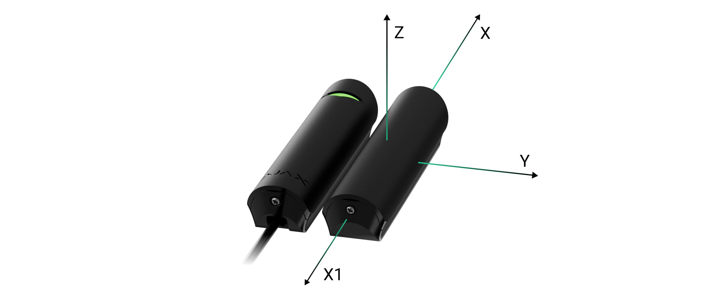
Relatively to the detector, the magnet can move along three axes: X (X1), Y, or Z. It depends on the DoorProtect Plus Fibra installation location. For example:
- X-axis (or X1): on the roller shutter.
- Y-axis: on the sliding door.
- Z-axis: on the window.
| Axis | Big magnet on the non-ferromagnetic surfaces (e.g., wooden doors) | Big magnet on the ferromagnetic surfaces (e.g., metal doors) | ||
| Removal distance, mm | Approach distance, mm | Removal distance, mm | Approach distance, mm | |
| X | 26 | 19 | 24 | 16 |
| X1 | 17 | 11 | 17 | 10 |
| Y | 28 | 16 | 26 | 15 |
| Z | 42 | 24 | 38 | 23 |
* — for small magnet all measurements will be reduced.
Do not exceed the boundary distance between the detector and the magnet. This may cause false alarms or detector malfunction (it will not react to closing/opening of the door or window).
Do not install the detector
- Outdoors, as this can lead to false alarms and detector failure.
- With two magnets at a time. DoorProtect Plus Fibra recognizes one magnet only on one side of the detector — left-hand or right-hand.
- With a magnet installed more than 1 cm (if a small magnet is used) or 2 cm (if a large magnet is used) away from the detector. This may result in false alarms or malfunction of the detector (it will not react to closing/opening of the door or window).
- Inside premises with temperature and humidity outside the permissible limits. This could damage the detector.
Do not install DoorProtect Plus Fibra with two magnets at a time. The detector recognizes only one magnet on one side — left or right.
Installation and connection
Before installing DoorProtect Plus Fibra, make sure to select the optimal location following the requirements of this manual! Cables must be hidden and located in a place that is difficult for burglars to access to reduce the likelihood of sabotage. Ideally, mount them in the walls, floor, or ceiling. Before final installation, test the detection zone and the Fibra signal strength.
DoorProtect Plus Fibra is connected with a 4-core cable: two cores for powering the device (+24V and GND) and two cores for data transmission (line A and line B).
When connecting to the device terminals, do not twist the wires together; solder them. The ends of the wires that will be inserted into the terminals should be tinned or crimped with special tips. This will ensure a reliable connection. Follow safety procedures and regulations for electrical installation work.
To mount a detector:
- Turn off the hub. Disconnect the external power and the hub backup battery.

1 — External power supply
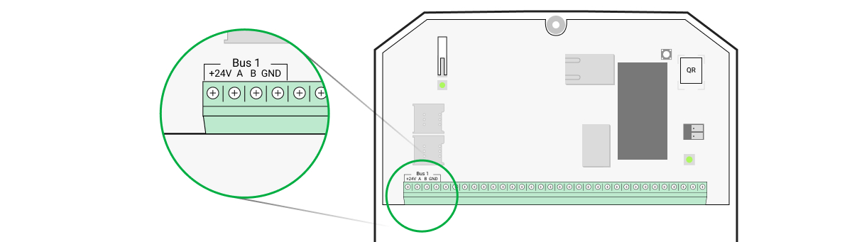
2 — Backup battery - Run the detector connection cable into the hub casing and connect the wires to the bus.
+24V — power supply input
А, B — signal terminals
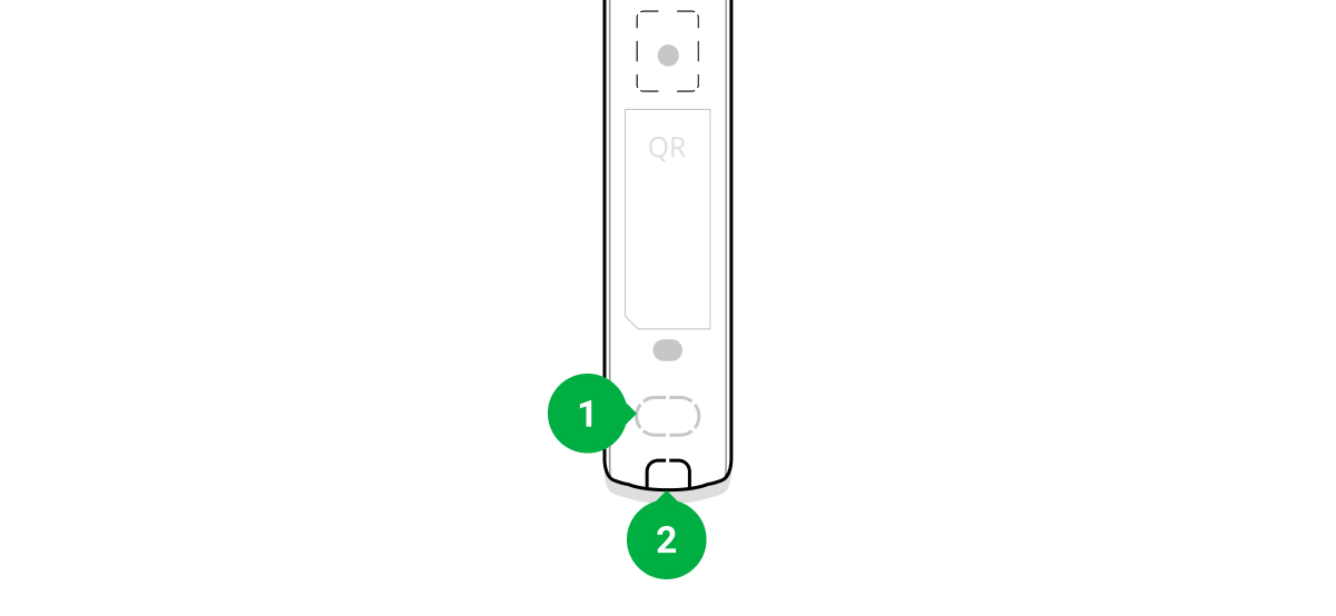
GND — ground - Remove the rear panel of the detector and gently break out the perforated part to lead the cable out.
- Route the cable from the hub into the detector enclosure through the hole made.
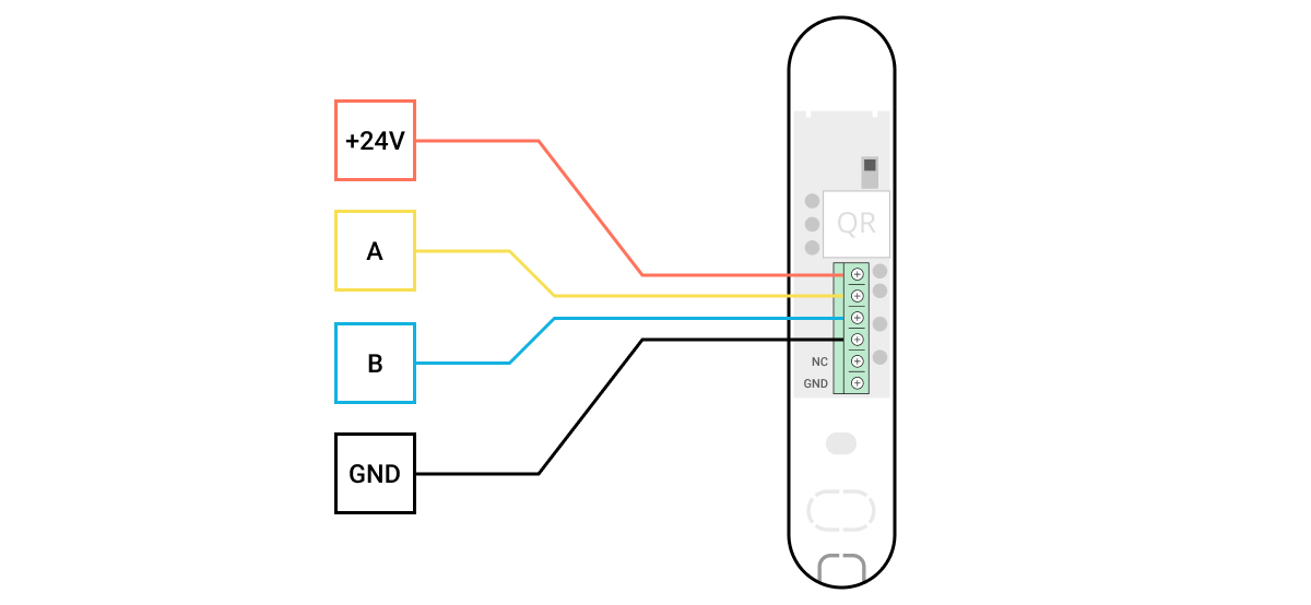
- Connect the wires to the terminals according to the scheme below. Follow the polarity and connection order of the wires. Securely fasten the wires to the terminals.
+24V — power supply input
А, B — signal terminals
GND — ground - If the detector is not the last one in the connection line, prepare a second cable in advance. The ends of the wires of the first and second cables, which will be inserted into the detector terminals, must be tinned and soldered together, or crimped with special tips.
- If the detector is the last one in the line and the Beam connection (Radial wiring) is used, install a terminating resistor by connecting it to the signal terminals of the device. When the Ring connection method is used, a terminating resistor is not needed.
We recommend using the Ring connection method (hub – device – hub). If the ring is broken, not a single device will be disabled. In this case, two beams are formed, which will continue to operate normally and transmit events to the hub. If the ring is broken, the users and security company receive notification.
- Temporarily secure the detector using a double-sided adhesive tape or other temporary fasteners at the chosen installation place.
- Where necessary, temporarily attach the magnet.
- Turn on the hub to supply power to the connected detector with power. When power is applied, a detector LED will notify that the power is turned on.
- Add a detector to the system.
- Conduct the Fibra Signal Strength Test. The recommended signal strength value is two or three bars. Otherwise, check the connection and the condition of the cable.
- Run a detection zone test:
- To check the opening sensor, open and close the window on which the device is mounted.
- Gently hit the window/door to check the shock sensor.
- To check the tilt sensor, tilt the window on which the detector is mounted.
- If the detector doesn’t respond to triggering in 5 out of 5 cases during the test, reconsider the installation location or method. The magnet may be too far from the detector, or the detector may be installed incorrectly.
- Secure the detector with bundled screws using at least two fixing points (with one fixing point in the perforated part of the mount above the tamper). When using other fasteners, make sure they do not damage or deform the mounting panel.
Double-sided tape can only be used for temporary installation. The device attached by the tape may come unstuck from the surface at any time. As long as the device is taped, the tamper will not be triggered when the device is detached from the surface.

Connecting a third-party wired detector
You can connect a wired NC (normally closed) detector of any type — motion, opening, or vibration — to DoorProtect Plus Fibra.
DoorProtect Plus Fibra does not power a third-party detector. It should be connected separately. For the type and voltage of the third-party detector, refer to the device documentation or contact the manufacturer’s support service.
Install a third-party detector at the distance no more than 1 meter away from DoorProtect Plus Fibra. Increasing the length of the wire degrades the quality of communication between devices.
To connect a third-party wired detector:
- Turn off and de-energize the hub. Disconnect the backup battery.
- Remove the front panel of DoorProtect Plus Fibra.
- Route the cable of the third-party wired detector into the DoorProtect Plus Fibra enclosure.
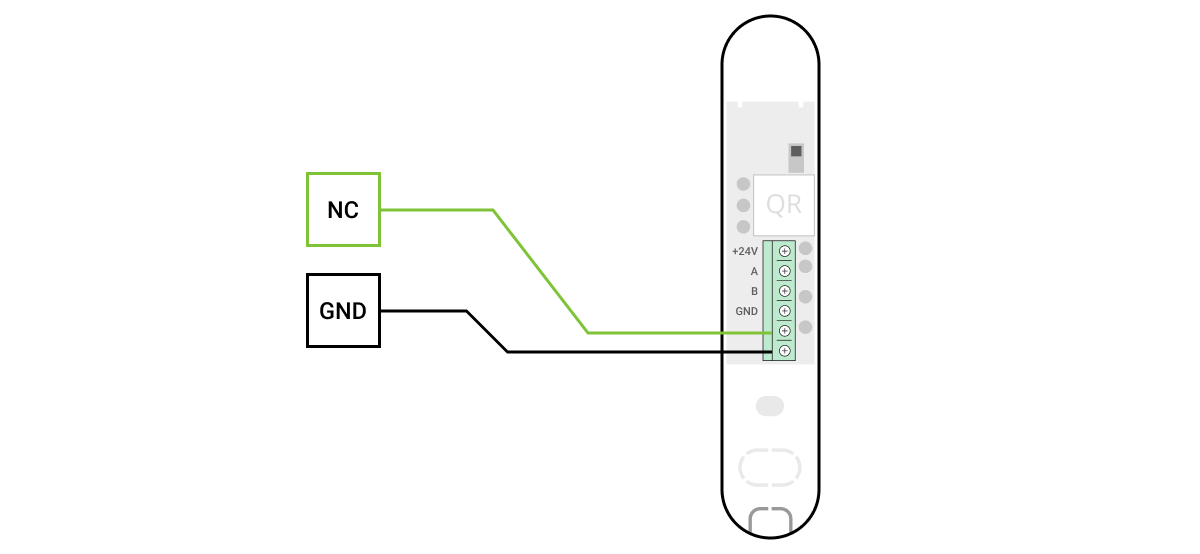
- Connect the wired detector to the DoorProtect Plus Fibra terminals.
NC — connection terminal
GND — ground - Turn on the hub.
- In the DoorProtect Plus Fibra settings, enable the External contact option.
- Check the operation of the connected wired detector.
Adding to the system
The detector is only compatible with Hub Hybrid (2G) and Hub Hybrid (4G). Adding and configuring Fibra devices is only possible through the Ajax PRO app by a user with administrator rights.
Before adding a device
- Install the PRO version of the app. Log in to a PRO account or create a new one if you don’t have it yet. Add a detector-compatible hub to the app, set the necessary settings, and create at least one virtual room.
- Turn on the hub and make sure it has access to the internet: via Ethernet and/or mobile network. You can do this in the Ajax app or by checking the LED on the hub board. It should light up white or green.
- Make sure the hub is disarmed and does not start updates by checking its status in the Ajax app.
- Make sure the detector is physically connected to the hub.
How to add DoorProtect Plus Fibra
There are two ways to add devices: manually and automatically.
To add a detector manually:
- Open the PRO version of the app. Select the hub you want to add DoorProtect Plus Fibra to.
- Go to the Devices tab and click Add device.
- Name the detector, scan, or type in the QR code (placed on the detector body and the packaging), select a room and a group (if the group mode is enabled).
- Click Add.
To have the detector added automatically:
- Open the PRO version of the app. Select the hub you want to add DoorProtect Plus Fibra to.
- Go to the Devices tab and click Add device.
- Select Add Bus Devices. After scanning, a list of all devices physically connected to the hub, which have not yet been added to the system, will be displayed on the screen. The devices are sorted by the buses they are physically connected to.
After scanning the buses, the detectors will be displayed in the Devices ![]() tab. The order of the devices will depend on which bus they are connected to.
tab. The order of the devices will depend on which bus they are connected to.
By default, the device name includes the detector name and its identifier. To connect detectors to a hub, edit their name, and assign a room and a group to the device (if the group mode is activated in the hub settings).
To check which detector you actually deal with, use either LED indication or detector triggering.
Method 1: Via LED indication
In the list of available devices to add, click on any option. The LED of this detector will start blinking after you press it. This way, you’ll know exactly which detector you’re adding, how to name it, and which room and group it should be assigned to.
To add a detector:
- Click the detector in the list.
- Create a name.
- Specify the room and the security group (if enabled).
- Click Save.
If the detector is connected to the hub successfully, it will disappear from the list of available detectors.
Method 2: By detector alarm
Enable the Add Detectors by Alarm option above the list of detectors.
Trigger an alarm. When triggered, the detector will move to the top of the list to the Recently triggered devices category. The detector will stay in this category for 5 seconds, after which it will move back to the bus category.
To add a detector:
- Click on the device in the list.
- Create a name.
- Specify the room and the security group (if enabled).
- Click Save.
If the detector connects to the hub successfully, it will disappear from the list of available detectors.
Device status updates in the list depend on the Fibra settings; the default value is 36 seconds.
If the connection fails, check the accuracy of the wired connection and try again. If hub already has the maximum number of devices added (for Hub Hybrid, the default is 100), you will get an error notification when you add one.
DoorProtect Plus Fibra only works with one hub. When connected to a new hub, the detector stops exchanging commands with the old one. Once added to a new hub, DoorProtect Plus Fibra is not removed from the list of devices of the old hub. This must be done through the Ajax app.
Malfunctions
When a detector identifies a fault (for example, there is no connection via the Fibra protocol), the Ajax app displays a malfunction counter in the upper left corner of the device icon.
All malfunctions can be seen in the detector states. Fields with malfunctions will be highlighted in red.
Malfunctiont is displayed if:
- The detector temperature is out of acceptable limits.
- The detector body is open (tamper is triggered).
- There is no connection with the hub via the Fibra protocol.
Icons
The icons display some DoorProtect Plus Fibra states. You can view them in the Ajax app on the Devices ![]() tab.
tab.
| Icon | Meaning |
|
Fibra signal strength — displays the signal strength between the hub and the detector. |
|
|
The detector operates in the Always Active mode. |
|
|
|
Entry and/or exit delay is enabled. |
|
DoorProtect Plus Fibra will work when the Night Mode is enabled. |
|
| DoorProtect Plus Fibra has detected the opening of a door or a window. The icon is displayed regardless of the security mode. | |
|
The external contact of the DoorProtect Plus Fibra detector is on. |
|
|
DoorProtect Plus Fibra has been deactivated. |
|
|
DoorProtect Plus Fibra has been disabled because the number of alarms was exceeded. |
|
|
DoorProtect Plus Fibra has been disabled by timer. |
|
|
DoorProtect Plus Fibra has tamper triggering events deactivated by a user or PRO with administrator rights. |
States
The states include information about the device and its operating parameters. DoorProtect Plus Fibra states can be found in the Ajax app:
- Go to the Devices tab.
- Choose DoorProtect Plus Fibra from the list.
| Parameter | Meaning |
| Temperature |
Detector temperature — it is measured on the processor and changes gradually. Acceptable measurement error between the value in the app and the room temperature: 2–4°C. The value is updated as soon as the detector identifies a temperature change of at least 1°C. |
| Fibra Signal Strength |
Signal strength between the hub and DoorProtect Plus Fibra. Recommended values — 2—3 bars. Fibra — protocol for transmitting DoorProtect Plus Fibra events and alarms. |
| Connection via Fibra | The status of the connection between the hub and the detector:
|
| Line Voltage | The voltage value on the Fibra line to which the detector is connected. |
| Lid | The status of the detector tampers that respond to detachment or violation of the integrity of the body:
When the front lid of DoorProtect Plus Fibra is open, the hub transmits the following event: “The front lid of DoorProtect Plus Fibra detector is open”. If DoorProtect Plus Fibra is detached from its mount, the hub transmits the following event: “DoorProtect Plus Fibra detector detached from the mount”. |
| Primary Detector | Primary detector state:
|
| External Contact | State of the external detector connected to DoorProtect Plus Fibra:
|
| Shock Sensor | Indicates if the shock sensor is active:
|
| Tilt Sensor | Indicates if the tilt sensor is active:
|
| Always Active |
When this option is enabled, the detector is constantly in the armed mode and reports opening of the door or window on which it is installed. |
| Permanent Deactivation | Shows the status of the device permanent deactivation function:
|
| Alarm Reaction | |
| Operating Mode | Shows how the detector reacts to alarms:
|
| Delay When Entering, sec |
If active, this option shows the delay time when entering (5 to 120 seconds). Delay when entering (alarm activation delay) is the time the user has to disarm the security system after entering the secured area. |
| Delay When Leaving, sec |
If active, this option shows the delay time when entering (5 to 120 seconds). Delay when leaving (arming delay) is the time the user has to leave the secured area after arming. |
| Delay when entering for the Night mode, sec |
If active, this option shows the delay time when entering in Night mode (5 to 120 seconds). Delay when entering (alarm activation delay) is the time the user has to disarm the security system after entering the premises. |
| Delay when leaving for the Night mode, sec |
If active, this option shows the delay time when leaving in Night mode (5 to 120 seconds). Delay when leaving (arming delay) is the time the user has to leave the premises after arming. |
| Firmware | Detector firmware version. |
| Device ID | Detector ID — Also available on the detector body and the packaging. |
| Device № | Device loop (zone) number. |
| Bus № | The number of the bus the device is physically connected to. |
Settings
To change the detector settings in the Ajax app:
- Go to the Devices tab.
- Choose DoorProtect Plus Fibra from the list.
- Go to Settings by clicking on the gear icon .
- Set the required parameters.
- Click Back to save the new settings.
| Settings | Meaning |
| Name |
Detector name. Displayed in the list of hub devices, SMS text, and notifications in the event feed. To change the detector name, click on the pencil icon The name can contain up to 12 Cyrillic characters or up to 24 Latin characters. |
| Room |
Selecting the virtual room to which DoorProtect Plus Fibra is assigned. The room name is displayed in the text of SMS and notifications in the event feed. |
| Alarm LED indication | Controls the flashing of the detector LED in case of alarm and tamper triggering:
|
| Primary Detector | When this option is enabled, the primary DoorProtect Plus Fibra detector reacts to opening and closing. |
| External Contact | If enabled, DoorProtect Plus Fibra registers alarms from an external detector. |
| Always Active |
When this option is enabled, the detector is constantly in the armed mode and detects opening of the door or window on which it is installed. |
| Activate siren if a door or window is open | When this option is enabled, the sirens connected to the system are activated when a door or window is opened. |
| Activate siren if an shutter detector is open | When this option is enabled, the sirens connected to the system are activated in case of an alarm from an external detector. |
| Alert with a siren if a roller shutter detector is disabled | If active, the sirens connected to the system are activated if an external detector is disabled. |
| Alert with a siren if a shock is detected | If active, the sirens connected to the system are activated if the detector registers a shock. |
| Alert with a siren if a incline is detected | If active, the sirens connected to the system are activated if the detector registers change the angle of inclination. |
| Chime Settings |
When this option is enabled and the system is not armed, when opening, the detector alerts by the sound signal of sirens. |
| Alarm Reaction | |
| Operating Mode | Specify how this device will react to alarms:
|
| Delay When Entering, sec |
Delay time when entering (5 to 120 seconds). Delay when entering (alarm activation delay) is the time the user has to disarm the security system after entering the secured area. |
| Delay When Leaving, sec |
Delay time when leaving (5 to 120 seconds). Delay when leaving (arming delay) is the time the user has to leave the secured area after arming. |
| Arm in Night Mode |
When this option is enabled, the detector will enter the armed mode when using the Night mode. |
| Delays in Night Mode |
When this option is enabled, the set entry/exit delays also work in the Night mode. |
| Fibra Signal Strength Test |
Switches the detector to the Fibra signal strength test mode. The test allows you to check the signal strength between the hub and the detector over the Fibra wired data transfer protocol to determine the optimal installation location. |
| Detection Zone Test |
Switches the detector to the detection zone test mode. The test enables the user to check the detector’s reaction to the movem ent and determine the optimal installation location. |
| User Guide | Opens the User Manual of DoorProtect Plus Fibra detector in the Ajax app. |
| Permanent Deactivation |
Allows to disable the device without removing it from the system. Three options are available:
The system can also automatically deactivate devices when the set number of alarms is exceeded or when the recovery time expires. |
| Unpair Device | Disconnects the detector from the hub and deletes its settings. |
How to set up chime
Chime is a sound signal Ajax siren that indicates triggering of opening detectors when the system is disarmed. The feature is used, for example, in stores, to notify employees that someone has entered the building.
Chime is configured in two stages: setting up opening detectors and setting up sirens.
Detectors settings
- Go to the Devices menu.
- Select the DoorProtect Plus Fibra detector.
- Go to its Settings by clicking the gear icon in the upper right corner.
- Go to the Chime settings menu.
- Select the events to be notified by the siren:
- If a door or a window is open.
- If an external contact is open (available if the External Contact option is enabled).
- Select the notification sound: 1 to 4 short beeps. Once selected, the Ajax app will play the sound.
- Click Back to save the settings.
- Set up the required siren.
Indication
| Indication | Event | Note |
| Lights up green for about a second. | Switching on the detector. | The detector turns on as soon as the hub feeds power. |
| Lights up for a couple of seconds until the detector is connected to the hub. | Connecting the detector to the hub. | |
| Lights up green for about one second. | Alarm/tamper triggering. | |
| When alarmed, it slowly lights up green and slowly goes out. | Low bus voltage (7 V or lower). |
Voltage of 7 V or less is considered low. Check the wired connection of the detector. |
Functionality testing
The Ajax system provides several types of tests that help you make sure that installation points of devices are selected correctly. DoorProtect Plus Fibra tests do not start straight away but begin no later than a single hub-detector ping period (36 seconds with a default hub settings). You can change the ping period of devices in the Fibra menu of the hub settings.
To run a test in the Ajax app:
- Select the hub if you have several of them or if you are using a PRO app.
- Go to the Devices menu .
- Choose DoorProtect Plus Fibra.
- Go to Settings .
- Select a test:
- Fibra Signal Sstrength Test
- Detection zone
- Launch and conduct a test.
Maintenance
Check the functioning of the detector regularly. The optimal frequency of checks is once every three months. Clean the detector body from dust, cobwebs, and other contaminants as they emerge. Use a soft dry cloth suitable for equipment care.
Do not use substances that contain alcohol, acetone, petrol, or other active solvents to clean the detector. Wipe the lens gently, as scratches may impair the detector sensitivity.
Technical specifications
Complete set
- DoorProtect Plus Fibra.
- SmartBracket mounting panel.
- Large magnet.
- Small magnet.
- Installation kit.
- Quick start guide.
Warranty
Warranty for the Limited Liability Company “Ajax Systems Manufacturing” products is valid for 2 years after the purchase.
If the device does not function correctly, please contact the Ajax Technical Support first. In most cases, technical issues can be resolved remotely.
Contact Technical Support:
Manufactured by “AS Manufacturing” LLC