WallSwitch is a power relay to control 110/230 V~ power supply remotely. The relay power supply is not galvanically isolated with terminal blocks; therefore, WallSwitch switches only the power received at the power supply terminal blocks. The device has an energy consumption meter and features three types of protection: voltage, current, and temperature.
Only a qualified electrician or installer should install WallSwitch.
WallSwitch controls the power supply of electrical appliances connected to the circuit with a load of up to 3 kW using Ajax apps, automation scenarios, the function button on the relay, and by pressing Button.
WallSwitch is connected to the Ajax system via the secure Jeweller radio protocol. The communication range is up to 1,000 meters in an open space. The device works only with Ajax radio signal range extenders and hubs.
Functional elements
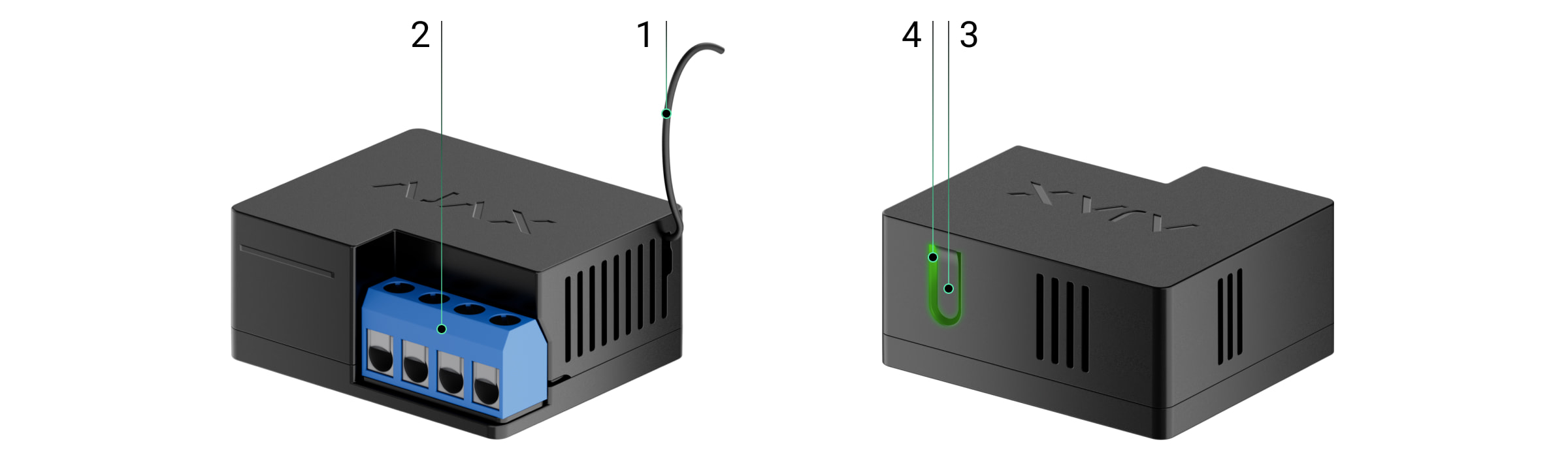
- Antenna.
- Terminal blocks.
- Function button.
- LED indicator.

IN terminals:
- L terminal — power supply phase connection terminal.
- N terminal — power supply neutral connection terminal.
OUT terminals:
- N terminal — power supply neutral output terminal.
- L terminal — power supply phase output terminal.
Operating principle
WallSwitch is a power relay of the Ajax system. The relay is installed in the electrical circuit gap to control the power supply of devices connected to this circuit. The relay can be controlled via the function button on the device (by holding it down for 2 seconds), the Ajax app, Button, and automation scenarios.
WallSwitch switches one single pole of the electrical circuit — the phase. In this case, the neutral is not commuted and remains closed.
WallSwitch can operate in bistable or pulse mode (pulse mode is available with firmware version 5.54.1.0 and higher). The pulse duration can be set in pulse mode from 1 to 255 seconds. The operating mode is selected by users or PRO with admin rights in Ajax apps.
The user or PRO with administrator rights can also set the normal state of the relay contacts (the function is available for WallSwitch with firmware version 5.54.1.0 and higher):
- Normally closed — the relay stops supplying power when activated and resumes when deactivated.
- Normally open — the relay supplies power when activated and stops when deactivated.
WallSwitch measures the current, voltage, the amount of energy consumed by electrical appliances, and the power they consume. This data, along with other operating parameters of the relay, is available in the device States. Relay states update frequency depends on Jeweller or Jeweller/Fibra settings; the default value is 36 seconds.
The maximum resistive load of the relay is 3 kW. If an inductive or capacitive load is connected, the maximum switching current drops to 8 A.
Automation scenarios
Ajax’s scenarios offer a new level of protection. With them, the security system not only notifies about a threat, but also actively resists it.
Scenario types with WallSwitch and examples of usage:
- By alarm. Lighting is switched on when an opening detector raises the alarm.
- By security mode change. The electric lock is automatically blocked when the object is armed.
- By schedule. The irrigation system in the yard is switched on according to the schedule for the specified time. Lighting and TV are switched on when the owners are away so the house doesn’t seem empty.
- By pressing Button. Switching on night lighting by pressing the smart button.
- By temperature. The heating is turned on when the temperature in the room is lower than 20°C.
- By humidity. The humidifier is switched on when the humidity level drops below 40%.
- By CO₂ concentration. Supply ventilation is turned on when the carbon dioxide concentration level exceeds 1000 ppm.
Scenarios by the Button pressing are created in the Button settings, scenarios by the humidity and CO₂ concentration levels are created in the LifeQuality settings.
Control via the app
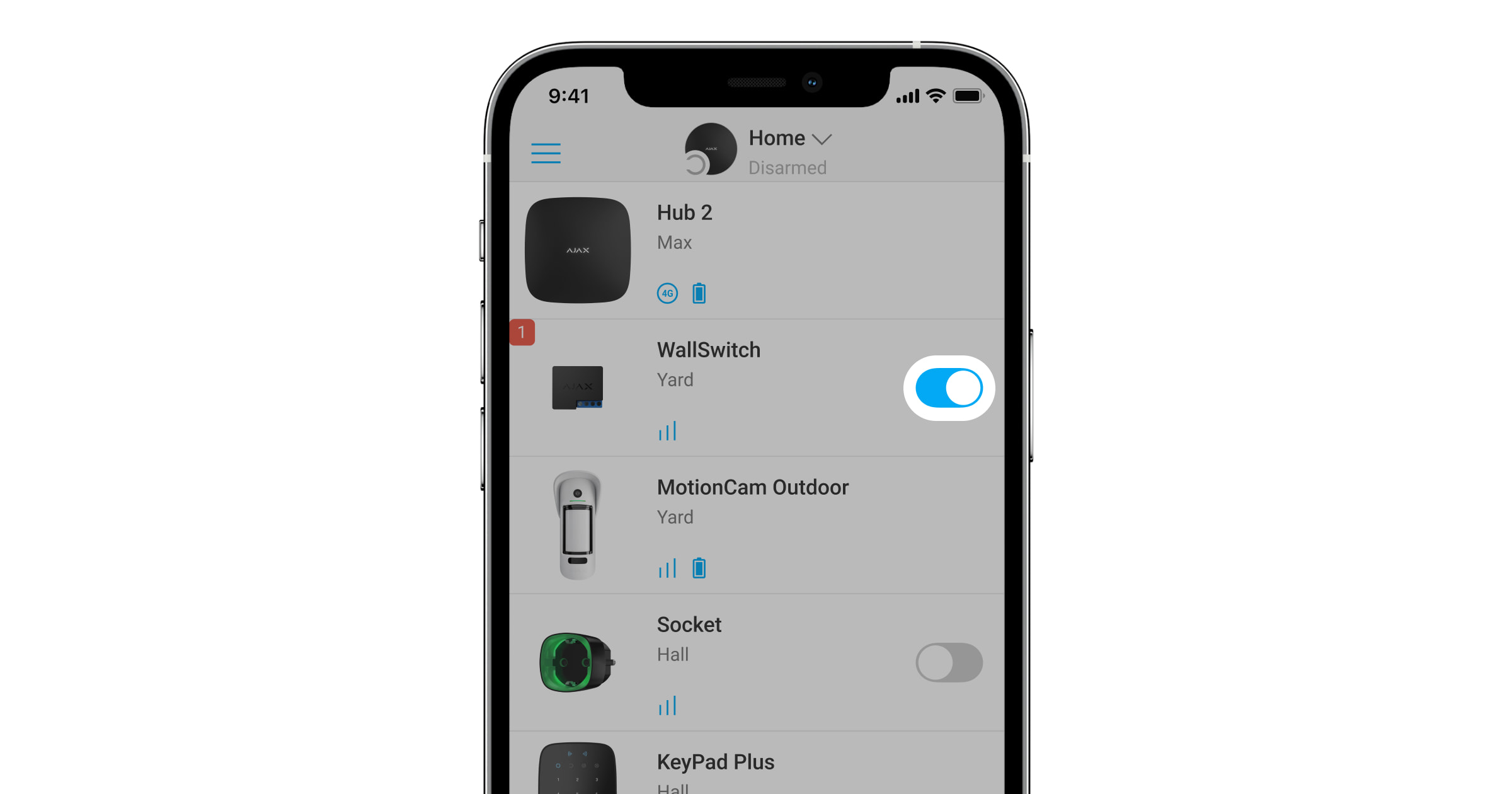
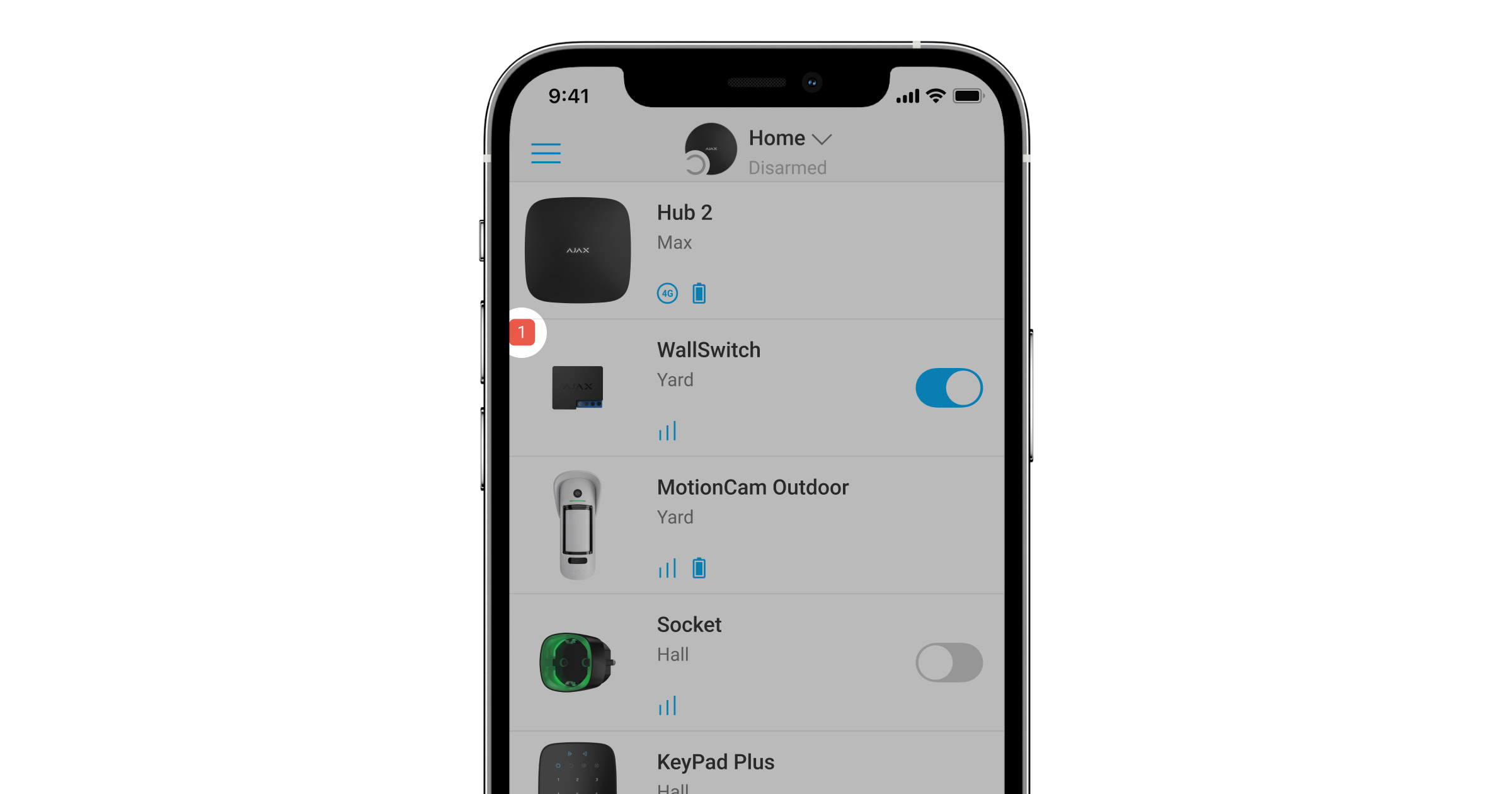
In Ajax apps, a user can switch on and off electrical appliances connected to an electrical circuit controlled by WallSwitch.
Click the toggle in the WallSwitch field in the Devices ![]() menu: the state of the relay contacts will change to the opposite, and the connected electrical device will switch off or on. This way, a security system user can remotely control the power supply, for example, for a heater or a humidifier.
menu: the state of the relay contacts will change to the opposite, and the connected electrical device will switch off or on. This way, a security system user can remotely control the power supply, for example, for a heater or a humidifier.
When WallSwitch is in pulse mode, the toggle will change from on/off to pulse.
Protection types
WallSwitch has three types of protection that operate independently: voltage, current, and temperature.
Voltage protection: is activated if the supply voltage exceeds the range of 184–253 V~ (for 230 V~ grids) or 92–132 V~ (for 110 V~ grids). Protects connected devices from voltage surges. We recommend disabling this protection for WallSwitch with firmware version below 6.60.1.30, which is connected to 110 V~ grids.
Current protection: is activated if the resistive load exceeds 13 A and inductive or capacitive load exceeds 8 A. Protects relays and connected devices from overcurrent.
Temperature protection: is activated if the relay heats up to temperatures above 65°C. Protects the relay from overheating.
When voltage or temperature protection is activated, the power supply through WallSwitch is stopped. Power supply resumes automatically when voltage or temperature returns to normal.
When the current protection is activated, the power supply will not be restored automatically; the user needs to use the Ajax app for this.
Energy consumption monitoring
In the Ajax app, the following energy consumption parameters are available for appliances connected via WallSwitch:
- Voltage.
- Load current.
- Power consumption.
- Power consumed.
Update frequency of parameters depends on Jeweller or Jeweller/Fibra polling period (default value is 36 seconds). Power consumption values are not reset in the app. To reset the readings, temporarily power off WallSwitch.
Jeweller data transfer protocol
WallSwitch uses the Jeweller radio protocol to transmit alarms and events. This wireless protocol provides fast and reliable two-way communication between the hub and connected devices.
Jeweller supports block encryption with a floating key and authentication of devices at each communication session to prevent sabotage and device spoofing. The protocol involves regular polling Ajax devices by the hub at intervals of 12 to 300 seconds (set in the Ajax app) to monitor communication with all devices and display their statuses in the app.
Sending events to the monitoring station
The Ajax system can transmit alarms and events to the PRO Desktop monitoring app as well as the central monitoring station (CMS) via SurGard (Contact ID), SIA DC-09 (ADM-CID), ADEMCO 685, and other proprietary protocols.
With PRO Desktop, the CMS operator receives all WallSwitch events. With other CMS software, a monitoring station receives only notification about connection loss between WallSwitch and the hub (or range extender).
The addressability of Ajax devices allows sending not only events but also the type of the device, its name, and room to PRO Desktop/CMS (the list of transmitted parameters may vary depending on the type of the CMS and the selected communication protocol).
The relay ID and zone number can be found in the WallSwitch States in the Ajax app.
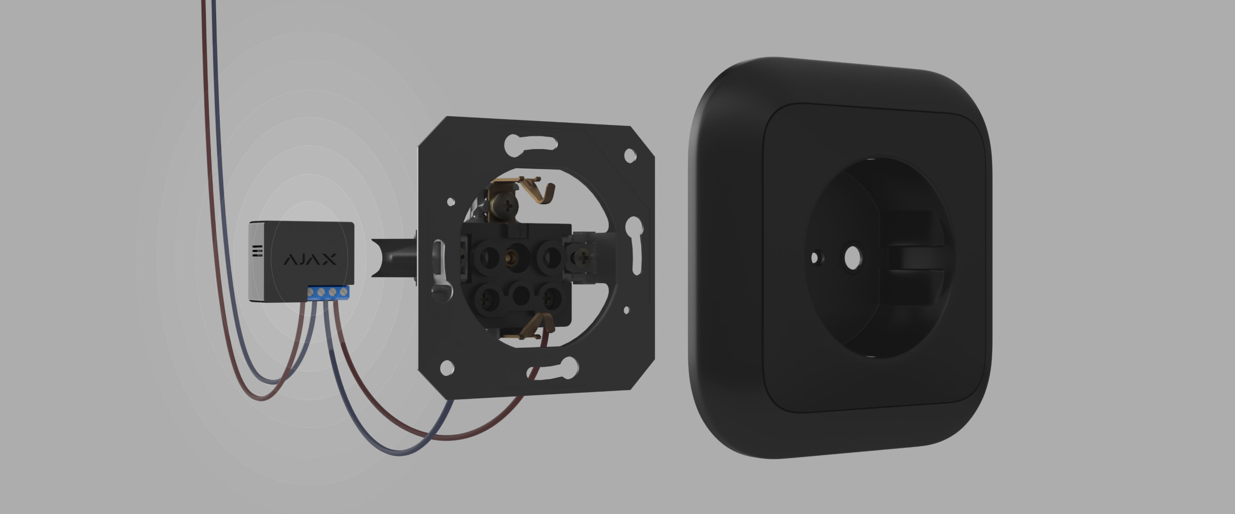
Selecting the installation spot
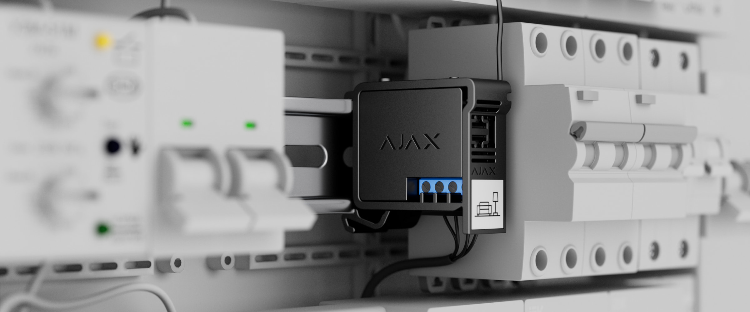
The device is connected to the 110/230 V~ grid. The WallSwitch dimensions (39 × 33 × 18 mm) allow installing the device into the deep junction box, inside the electrical appliance enclosure, or in the distribution board. A flexible external antenna ensures stable communication. To install WallSwitch on a DIN rail, we recommend using a DIN Holder.
WallSwitch should be installed with a stable Jeweller signal strength of 2–3 bars. To roughly calculate the signal strength at the place of installation, use a radio communication range calculator. Use a radio signal range extender if the signal strength is less than 2 bars at the intended installation location.
Do not install WallSwitch:
- Outdoors. Doing so may cause the device to malfunction or not work correctly.
- In rooms where the humidity and temperature do not correspond to the operating parameters. Doing so may cause the device to malfunction or not work correctly.
- Near sources of radio interference: for example, at a distance of less than 1 meter from a router. This can lead to a loss of connection between WallSwitch and the hub (or range extender).
- In places with low or unstable signal strength. This can lead to a loss of connection between the relay and the hub (or range extender).
Installing
Only a qualified electrician or installer should install WallSwitch.
Before installing the relay, ensure that you have selected the optimal location and that it complies with the requirements of this manual. When installing and operating the device, follow the general electrical safety rules for using electrical appliances and the requirements of electrical safety regulations.
When installing WallSwitch in the junction box, lead out the antenna and place it under the plastic frame of the socket. The bigger the distance between the antenna and metal structures, the lower the risk of interfering with and deteriorating the radio signal.
When connecting, it is recommended to use cables with a cross-section of 0.75—1.5 mm² (22-14 AWG). WallSwitch should not be connected to circuits with a load of more than 3 kW.
To install WallSwitch:
- If you install WallSwitch on a DIN rail, fix DIN Holder to it first.
- De-energize the power cable to which WallSwitch will be connected.
- Connect the phase and neutral to the power terminals of WallSwitch. Then connect the wires to the output terminals of the relay.

- Place the relay in DIN Holder. If the relay is not mounted on the DIN rail, we recommend securing WallSwitch with double-sided tape if it’s possible.
- Secure the wires if necessary.

Do not shorten or cut the antenna. Its length is optimal for operation in the Jeweller radio frequency range.
After installing and connecting the relay, be sure to run the Jeweller Signal Strength Test, and also test the overall operation of the relay: how it responds to commands, and whether it controls the power supply of the devices.
Connecting
Before connecting the device
- Install the Ajax app. Log in to your account or create a new account if you don’t have one.
- Add a compatible hub to the app, make the necessary settings, and create at least one virtual room.
- Make sure that the hub is on and has Internet access via Ethernet, Wi-Fi, and/or mobile network. You can do this in the Ajax app or by checking the hub LED indicator. It should light up white or green.
- Make sure the hub is not armed and does not start updates by checking its status in the Ajax app.
Only a user or a PRO with admin rights can connect the relay to the hub.
In order to connect WallSwitch to the hub
- Connect WallSwitch to a 110–230 V⎓ supply circuit if you haven’t done this before, and wait for 30 to 60 seconds.
- Sign in to the Ajax app.
- Select a hub if you have several of them or if you are using the PRO app.
- Go to the Devices menu and click Add Device.
- Name the device, select the room, scan the QR code (located on the relay and its packaging), or type the ID of the device.
- Click Add; the countdown will begin.
- Press the function button on WallSwitch. If this is not possible (for example, if WallSwitch is installed in a junction box), apply a load of at least 20 W to the relay for 5 seconds. For example, turn on the kettle, wait a few seconds, and turn it off.

To add WallSwitch, it must be within the hub’s radio coverage. If the connection fails, try again in 5 seconds.
If the maximum number of devices is added to the hub, when the user tries to add WallSwitch, he will get a notification about exceeding the device limit in the Ajax app. The maximum number of devices connected to the hub depends on the central unit model.
WallSwitch only works with one hub. When connected to a new hub, it stops sending notifications to the previous one. Once added to a new hub, WallSwitch is not removed from the list of devices of the old hub. This has to be done in the Ajax app.
After pairing with the hub and removing from the hub the relay contacts are open.
Malfunctions counter
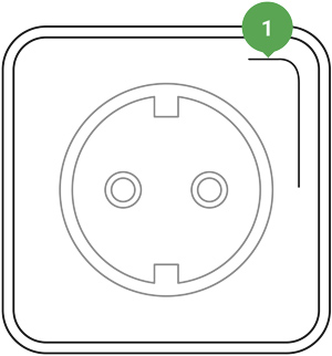
In case of a WallSwitch fault (e.g., no Jeweller signal between the hub and the relay), the Ajax app displays a malfunction counter in the upper-left corner of the device icon.
Malfunctions are displayed in the relay States. Fields with malfunctions will be highlighted in red.
Malfunction is displayed if:
- Current protection was activated.
- Temperature protection was activated.
- Voltage protection was activated.
- There is no connection between WallSwitch and the hub (or radio signal range extender).
Icons
Icons display some of WallSwitch states. You can see them in the Ajax app in the Devices ![]() tab.
tab.
| Icon | Meaning |
|
Jeweller signal strength between WallSwitch and the hub (or radio signal range extender). The recommended value is 2–3 bars. |
|
| The device is connected via a radio signal range extender. The icon is not displayed if WallSwitch works directly with the hub. | |
|
Current protection was activated. |
|
|
Voltage protection was activated. |
|
|
Temperature protection was activated. |
States
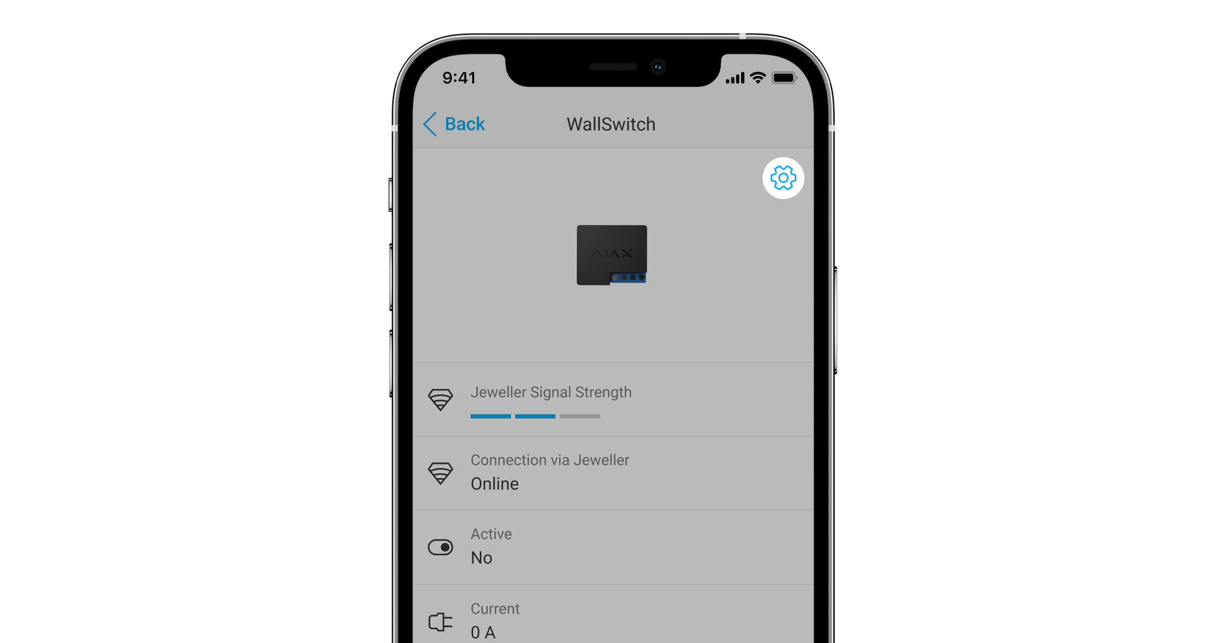
The states display information about the device and its operating parameters. WallSwitch states are available in the Ajax app. In order to do so:
- Go to the Devices tab.
- Select WallSwitch in the list.
| Parameter | Meaning |
| Jeweller Signal Strength |
Jeweller is a protocol for transmitting the events and alarms. The field displays the Jeweller signal strength between WallSwitch and the hub or radio signal range extender. Recommended values: 2–3 bars. |
| Connection via Jeweller | Connection status between WallSwitch and the hub or radio signal range extender:
|
| ReX | Displays the connection status of WallSwitch to the radio signal range extender:
The field is displayed if WallSwitch is operated via a radio signal range extender. |
| Active | WallSwitch contacts status:
The field is displayed if WallSwitch operates in the bistable mode. |
| Current |
The actual value of current that WallSwitch is switching. The frequency of value updates depends on the Jeweller settings. The default value is 36 seconds. |
| Voltage |
The actual value of voltage that WallSwitch is switching. The frequency of value updates depends on the Jeweller settings. The default value is 36 seconds. |
| Current Protection | Current protection state:
The relay will automatically continue to operate when voltage returns to normal. |
| Voltage Protection | Voltage protection state:
The relay will automatically continue to operate when the voltage returns to normal. We recommend disabling this protection if WallSwitch is connected to 110 V~ grids (only for the devices with a firmware version below 6.60.1.30). |
| Power |
The power consumption of an appliance connected to the circuit. The frequency of value updates depends on the Jeweller settings. The default value is 36 seconds. The power consumption values are displayed in increments of 1 W. |
| Electric Energy Consumed |
The electrical energy is consumed by an electrical appliance or appliances connected to the circuit that WallSwitch commutes. The frequency of value updates depends on the Jeweller settings. The default value is 36 seconds. The power consumption values are displayed in increments of 1 W. The counter is reset when WallSwitch is powered off. |
| Deactivation | Shows the status of WallSwitch deactivation function:
|
| Firmware | Relay firmware version. |
| ID | Device ID/serial number. It can be found on the device body and packaging. |
| Device No. | WallSwitch loop (zone) number. |
Configuring
To change WallSwitch settings in the Ajax app:
- Go to the Devices tab.
- Select WallSwitch in the list.
- Go to Settings by clicking on the gear icon .
- Set the parameters.
- Click Back to save the new settings.
| Setting | Setting |
| Name |
WallSwitch name. Displayed in the text of SMS and notifications in the event feed. To change the device name, click on the pencil icon The name can contain up to 12 Cyrillic characters or up to 24 Latin characters. |
| Room |
Selecting the virtual room to which WallSwitch is assigned. The room name is displayed in the text of SMS and notifications in the event feed. |
| Notifications | Selecting the relay notifications:
The setting is available when WallSwitch is connected to all hubs (except for the Hub model) with firmware version OS Malevich 2.15 or higher and in apps of the following versions or higher:
|
| Current Protection | Current protection setting:
The relay will automatically continue to operate when voltage returns to normal. |
| Voltage Protection | Voltage protection setting:
The relay will automatically continue to operate when voltage returns to normal. We recommend disabling this protection if WallSwitch is connected to 110 V~ grids (only for the devices with a firmware version below 6.60.1.30). |
| Mode | Selecting the relay operating mode:
The setting is available with firmware version 5.54.1.0 and higher. |
| Pulse Duration |
Selecting the pulse duration: 1 to 255 seconds. The setting is available when WallSwitch operates in the pulse mode. |
| Contact State | Selecting the relay contacts normal states:
|
| Scenarios |
It opens the menu for creating and configuring automation scenarios. Scenarios offer a new level of property protection. With them, the security system not only notifies about a threat, but also actively resists it. Use scenarios to automate security. For example, switch on lighting in the facility when an opening detector raises the alarm. |
| Jeweller Signal Strength Test |
Switching the relay to the Jeweller signal strength test mode. The test allows you to check the signal strength of Jeweller and the stability of the connection between WallSwitch and the hub or range extender to choose the best place to install the device. |
| User Guide | Opens the relay User Manual in the Ajax app. |
| Deactivation |
Allows to disable the device without removing it from the system. Two options are available:
After disconnecting WallSwitch will keep the state it had at the time of disconnection: active or inactive. |
| Unpair Device | Disconnects the relay from the hub and removes its settings. |
Indication
WallSwitch LED indicator flashes periodically if the device is not added to the hub. When you press the function button on the relay, the LED indicator lights up green.
Functionality testing
WallSwitch functionality tests do not begin immediately, but not later than over a single hub—device polling period (36 seconds with default settings). You can change the device polling period in the Jeweller or Jeweller/Fibra menu in the hub settings.
To run a test in the Ajax app:
- Select the hub if you have several of them or if you are using the PRO app.
- Go to the Devices tab.
- Select WallSwitch.
- Go to the Settings .
- Select and run the Jeweller Signal Strength Test.
Maintenance
The device requires no technical maintenance.
Technical specifications
| Assignment of the control device | Electrically operated control device |
| Design of the control device | Flush-mounted built-in control device |
| Automatic action type of the control device | Action type 1 (electronic disconnection) |
| Number of switching | Min 200,000 |
| Power supply voltage | 230 V~, 50 Hz |
| Rated pulse voltage | 2,500 V~ (Overvoltage category II for single-phase system) |
| Voltage protection | For 230 V~ grids: Maximum — 253 V~ Minimum — 184 V~ For 110 V~ grids: We recommend disabling this protection if WallSwitch is connected to 110 V~ grids (only for the devices with a firmware version below 6.60.1.30). |
| Cross-sectional area of the cable | 0,75–1,5 mm² (22–14 AWG) |
| Maximum load current | 10 А |
| Maximum current protection | Available, 13 A |
| Output power (resistive load 230 V~) for EAEU countries |
Up to 2.3 kW |
| Output power (resistive load 230 V~) for other regions |
Up to 3 kW |
| Operating mode |
Pulse or bistable (firmware version 5.54.1.0 and higher. Production date from March 5, 2020) Bistable only (firmware version under 5.54.1.0) |
| Pulse duration | 1 to 255 s (firmware version 5.54.1.0 and higher) |
| Energy consumption monitoring | Available are: current, voltage, power consumption, electrical energy meter |
| Energy consumption of the device in standby mode | Less than 1 W |
| Radio communication protocol |
Jeweller |
| Radio frequency band | 866.0 – 866.5 MHz 868.0 – 868.6 MHz 868.7 – 869.2 MHz 905.0 – 926.5 MHz 915.85 – 926.5 MHz 921.0 – 922.0 MHz Depends on the sales region. |
| Compatibility | All Ajax hubs, and radio signal range extenders |
| Radio signal modulation | GFSK |
| Radio signal range | Up to 1,000 m in an open space |
| Pollution degree | 2 for indoor use only |
| Protection class | IP20 |
| Operating temperature range | From 0°С to +64°С |
| Maximum temperature protection | Available, +65°C |
| Operating humidity | Up to 75% |
| Dimensions | 39 × 33 × 18 mm |
| Weight | 30 g |
| Service life | 10 years |
Complete Set
- WallSwitch.
- Wires — 2 pcs.
- Quick Start Guide.
Warranty
Warranty for the Limited Liability Company “Ajax Systems Manufacturing” products is valid for 2 years after the purchase.
If the device does not function correctly, please contact the Ajax Technical Support first. In most cases, technical issues can be resolved remotely.
Contact Technical Support: