The Ajax system not only provides theft and fire protection but also prevents site flooding attributed to pipe breaks or failures of plumbing fixtures. To implement the water leak prevention system, you will need a LeaksProtect water leak detector, a compatible electric valve, and a WallSwitch relay or Relay.
You can use third-party detectors in addition to LeaksProtect. Connect them to the Ajax system with the integration modules: Transmitter Jeweller, MultiTransmitter Jeweller, and MultiTransmitter Fibra.
Using the Ajax relay, you can shut off the water supply manually with the app or automatically: by alarm of the leak detector, by schedule, by changing the security mode, or by other scenarios.
You can automatically shut off the water without relays and third-party electric valves with WaterStop. It is a smart water shutoff valve from Ajax.
Only a qualified electrician can install WallSwitch and Relay, regardless of the electrical circuit type that accommodates the device.
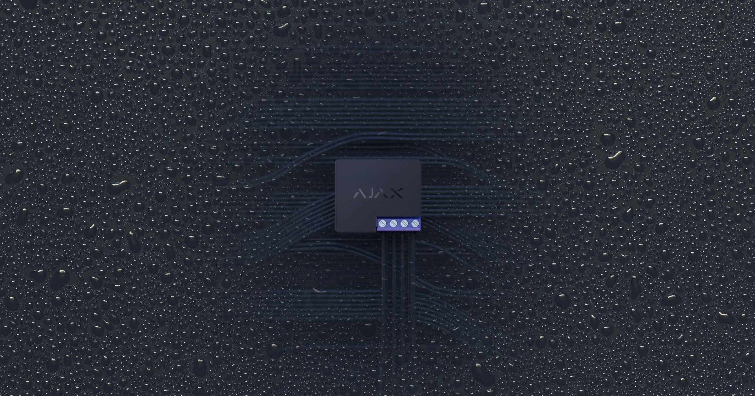
The relay opens and closes electrical circuits and can control the power supply of electrical appliances.
- Relay is a low-current remote control relay with a voltage-free “dry contact”.
- WallSwitch is a power relay to control power supply remotely with an energy consumption meter.
Both devices are remotely controlled via the Ajax app. The app allows you to set up automatic closing and/or opening of the relay contacts when changing the armed state and using the Night Mode.
Use a DIN Holder bracket to install Relay or WallSwitch on a DIN rail.
How to choose an electric valve to shut off the water
The electric valve opens and shuts off the water supply when it receives an electrical signal. When choosing an electric valve, pay attention to the following parameters:
- Pipe diameter and threaded connection type of the fitting.
- Valve type. Valves are either normally closed or normally open. There are also special electric valves with two stable states that alternate when a DC pulse is applied.

Normally closed valves are used most frequently. Unlike normally open valves, they shut off the water when external power is lost.
- Power supply voltage. Electric valves operate at different DC and AC voltages: 230 V~, 24 V ~, 24 V⎓, 12 V⎓, etc.
- Manual control. The rotating mechanism provides manual electric valve control similar to a common tap. This allows you to shut off the water even if the phone is unavailable.
- The number of control inputs — one or two control inputs or controlled by polarity inversion of the electrical supply at the input.
Normally closed valves with one control input are the most suitable to implement the water shut-off system based on the Ajax system. No coupling relays are required to connect the valves of this type. If you use pulse valves, the Ajax app will not know the valve state: open or closed. Relay requires electric valves operating at 12/24 V⎓ and WallSwitch — at 230 V~.
The valve should have two power supply sources: the main power source (electricity grid) of the site and the backup battery. In this case, you will be able to shut off the water even if the building is disconnected. It is easier and cheaper to provide 12/24 V⎓ backup power supply rather than 230 V~.
Layout diagram of the Relay connection to a 12/24 V⎓ electromagnetic valve
During mounting and operating, follow the general electrical safety rules for using electrical appliances as well as the requirements of electrical safety laws and regulations.
When power is lost, the Relay contacts remain in the open state. After the external power is restored, the Relay contacts restore their initial state.
Connection to the electric valve with one control input
Provide a 12/24 V⎓ external power source to implement connection according to the diagram.
A single power supply source can power Relay and the electric valve. When mounting the device, do not allow moisture to penetrate Relay or the cable connections site.
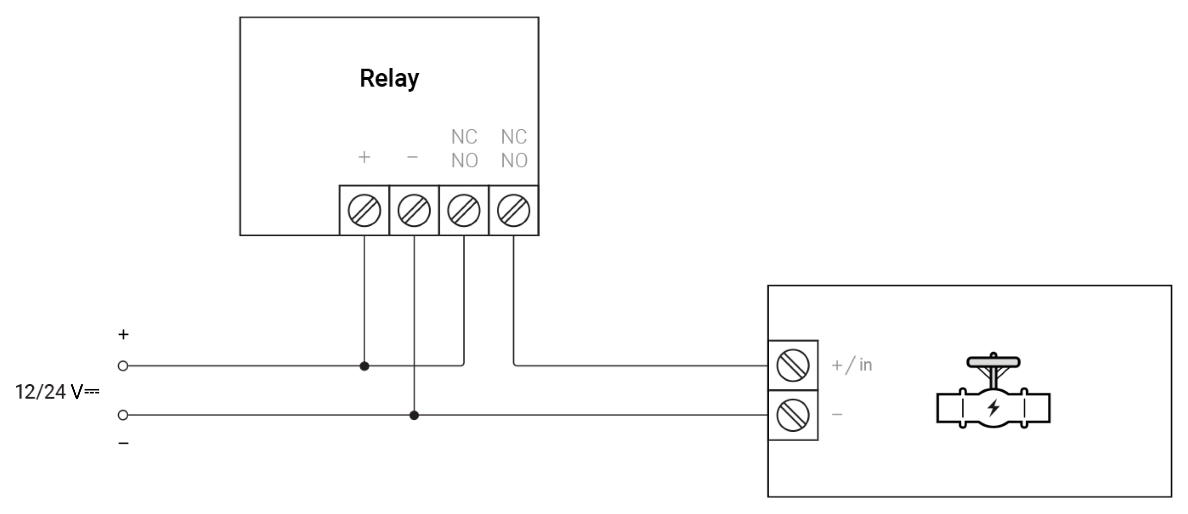
- Connect the power supply source to the power terminals of the relay.
- Connect the “+” contact terminal of the power source to one of the relay contact terminals and the “+/in” contact (control input) of the electromagnetic valve — to the other relay contact terminal.
- Connect the “–” contact terminal of the electromagnetic valve to the “–” contact terminal of the power source.
Such connection ensures closing of the electromagnetic valve using Relay.
Valve examples:
- PIE T20-S2-B
- CONVA A20-T25-S2-C
- Ebowan 12 V DC
Operation of the 12/24 V⎓ electromagnetic valve with one control input
Relay set up
- Go to the Devices tab.
- Open the Relay menu.
- Open Settings .
- Select Bistable operation mode.
- Set the Contact State — Normally Open.
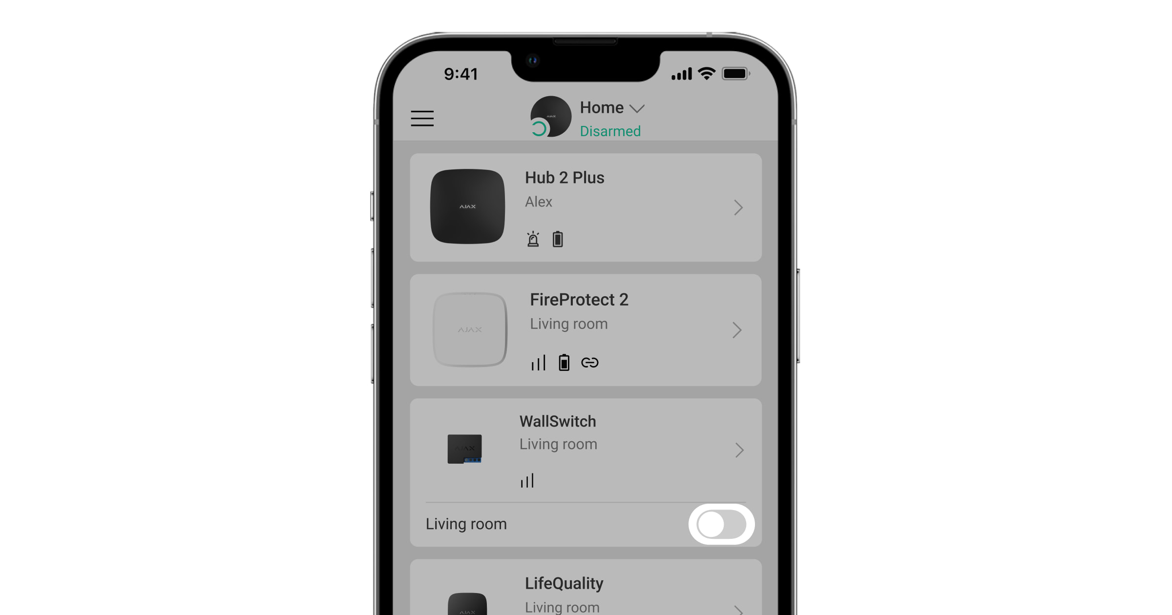
Operation of the electric valve in the Ajax app
Click the switch in the Relay line — the state of the relay contact terminals will change to the opposite.
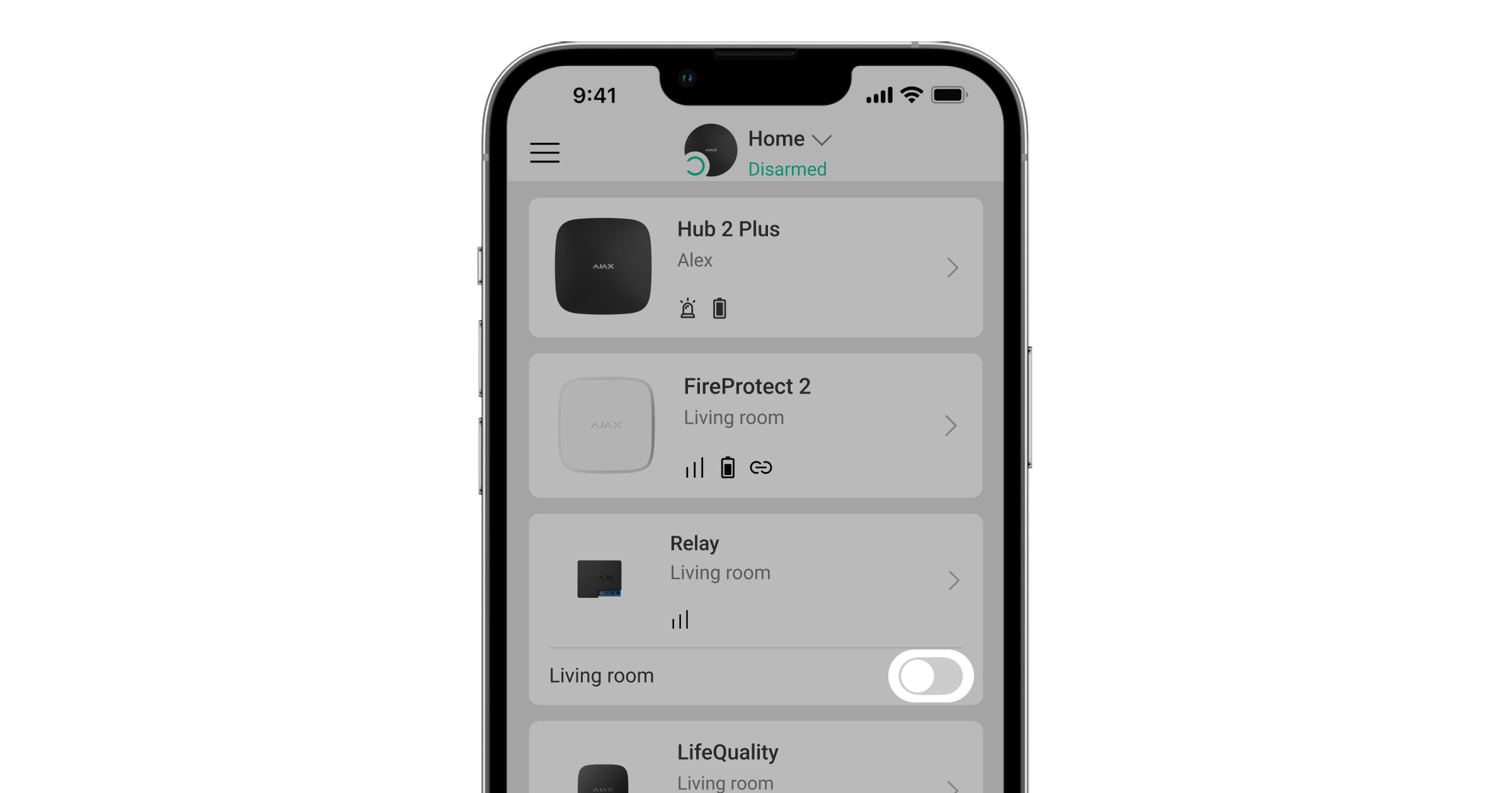
When the Relay contact terminals are closed, the electric valve receives power and opens. When opened, the electric valve remains unpowered and the water is shut off.
Connection to the electric valve with two control inputs
Provide a 12/24 V⎓ external power source and an SPDT-type coupling relay (12/24 V⎓) to implement connection according to the diagram.
A single power source can power Relay, coupling relay, and electric valve. When mounting the device, do not allow moisture to penetrate Relay, the coupling relay, or the cable connections site.
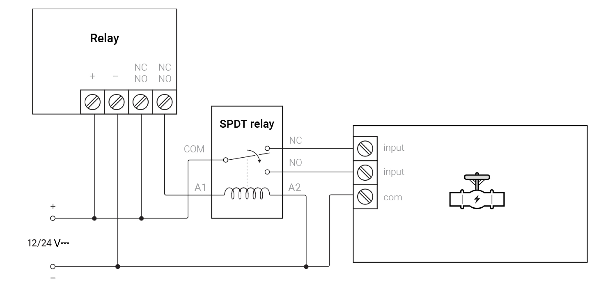
- Connect the power supply source to the power terminals of Relay.
- Connect the “+” contact terminal of the power source to one of the Relay contact terminals and the A1 contact terminal of the coupling relay — to the other Relay contact terminal.
- Connect the com contact terminal of the electromagnetic valve (common contact) and the A2 contact terminal of the coupling relay to the “–” contact terminal of the power source.
- Connect the COM contact terminal of the coupling relay to the “+” contact terminal of the power source.
- Connect the NC contact terminal of the coupling relay to the control opening input of the electric valve, and the NO contact terminal — to the closing input.
Such connection ensures closing of the electromagnetic valve using Relay.
Operation of the 12/24 V⎓ electromagnetic valve featuring two control inputs
Relay set up
- Go to the Devices tab.
- Open the Relay menu.
- Open Settings .
- Select Bistable operation mode.
- Set the Contact State — Normally Closed.
Operation of the electric valve in the Ajax app
Click the switch in the Relay line — the state of the relay contact terminals will change to the opposite.
When contacts close, the valve closes; when contacts open, the valve opens.
Connection to electric valve featuring “polarity inversion” control input
Provide a 12/24 V⎓ external power supply source and a DPDT-type coupling relay (12/24 V⎓) to implement connection according to the diagram.
A single power source can power Relay, coupling relay, and electric valve. When mounting the device, do not allow moisture to penetrate Relay, the coupling relay, or the cable connections site.
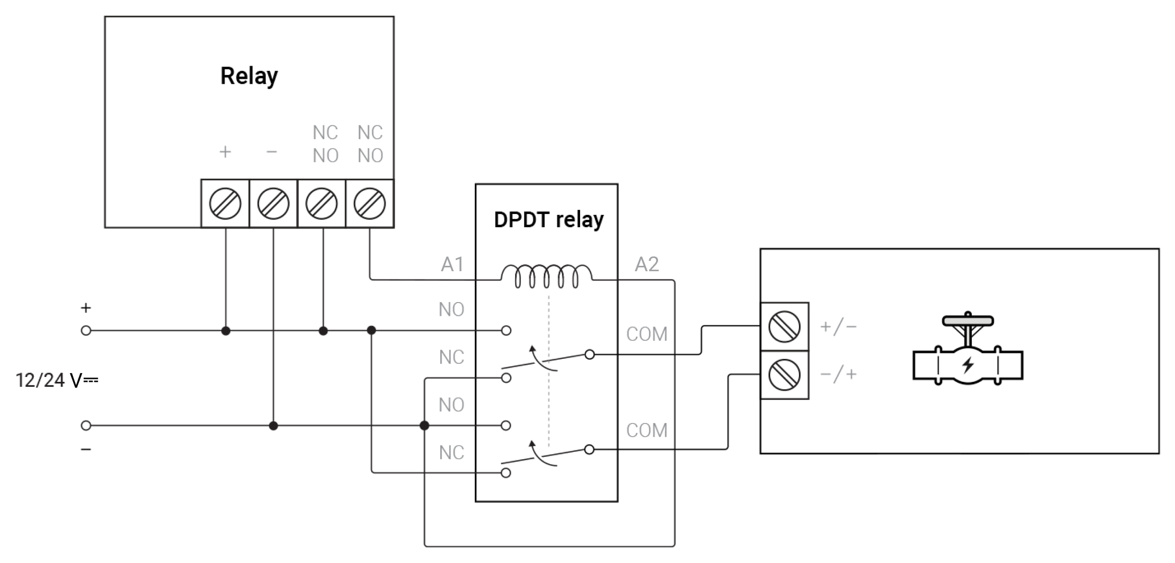
- Connect the power supply source to the power terminals of Relay.
- Connect the “+” contact terminal of the power source to one of the Relay contact terminals and the A1 contact terminal of the coupling relay — to the other Relay contact terminal.
- Connect the NO contact terminal of the relay’s first contact group to the “+” contact terminal, and the NC contact terminal — to the “–” contact terminal of the power source.
- Connect the NO contact terminal of the relay’s second contact group to the “–” contact terminal, and the NC contact terminal — to the “+” contact terminal of the power source.
- Connect the COM contact terminal of the relay’s first contact group to the first control input, and the COM contact terminal of the relay’s second contact group — to the second control input of the electric valve.
- Connect the A2 contact terminal of the coupling relay to the “–” contact terminal of the power source.
Such connection ensures operation of the coupling relay that supplies power of variable polarity to the electric valve control inputs using Relay. The polarity of the input voltage determines the electric valve state: open or closed.
Valve examples:
- COVNA A20-T15-S2-C
- CVX-15N
Operation of the 12/24 V⎓ electromagnetic valve featuring polarity inversion control
Relay set up
- Go to the Devices tab.
- Open the Relay menu.
- Open Settings .
- Select Bistable operation mode.
- Set the Contact State — Normally Closed.
Operation of the electric valve in the Ajax app
Click the switch in the Relay line — the state of the relay contact terminals will change to the opposite.
When contacts close, the valve closes; when contacts open, the valve opens.
Layout diagram of the WallSwitch connection to a 230 V~ electromagnetic valve
During mounting and operating, follow the general electrical safety rules for using electrical appliances as well as the requirements of electrical safety laws and regulations.
Connection to the 230 V~ electric valve with one control input
Provide a 230 V~ external power supply source to implement connection according to the diagram.
A single power supply source can power WallSwitch and the electric valve. When mounting the device, do not allow moisture to penetrate WallSwitch or the cable connections site.
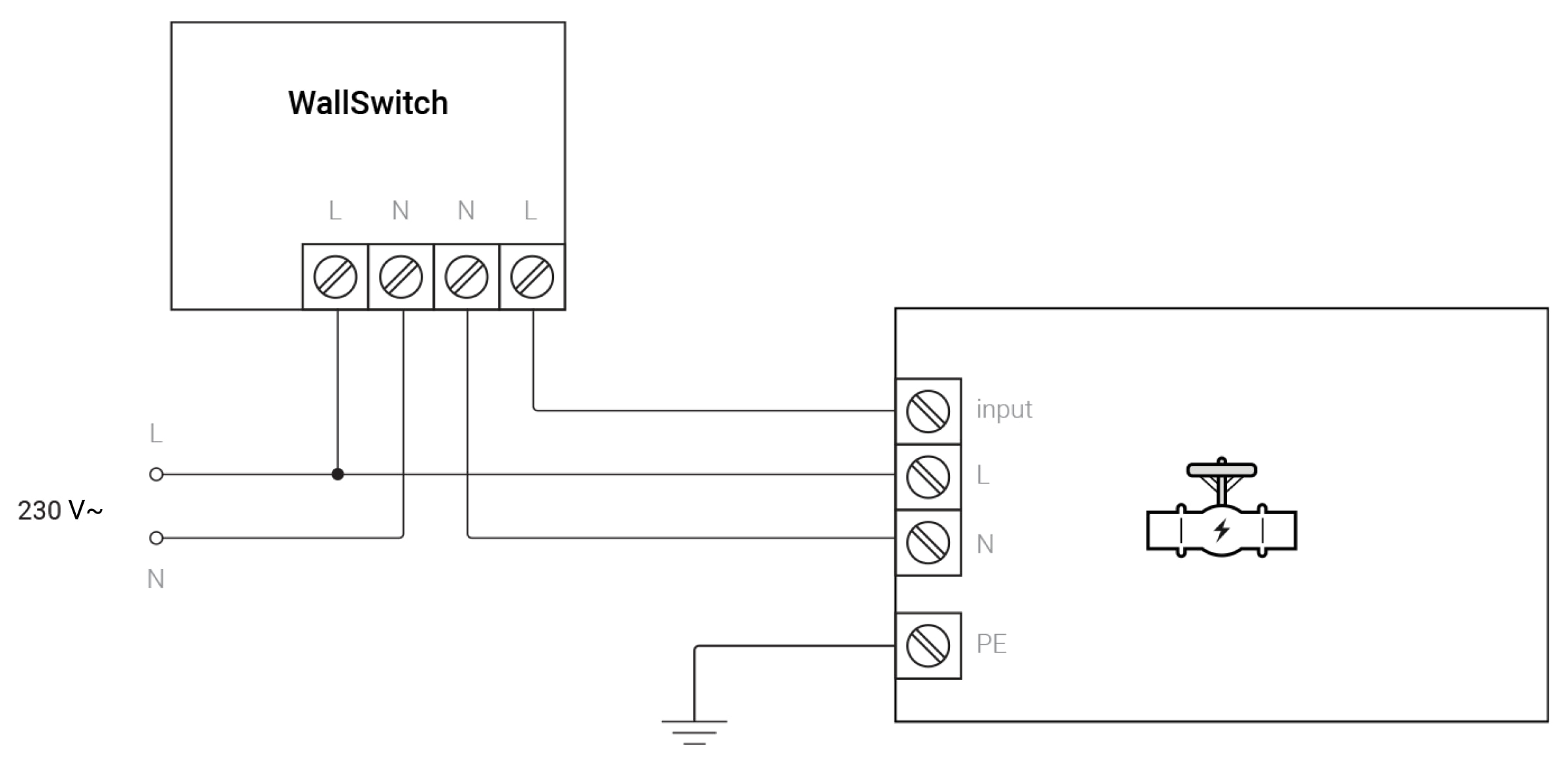
- Connect the power supply source to the power terminals of WallSwitch observing the polarity.
- Connect the N output terminal (neutral) of WallSwitch to the N contact terminal of the electric valve.
- Connect the L output terminal (phase) of WallSwitch to the control input of the electric valve.
- Connect the L contact terminal of the electric valve to the 230 V~ phase of the power source.
- Ground the PE contact terminal of the electric valve.
Such connection ensures the closing of the electromagnetic valve using WallSwitch. When the WallSwitch contacts close, the valve closes. When they open, the valve opens.
Some valves enable selection of the normal state: open or closed when control input is closed.
Valve examples:
- ESBE MBA 100 series
- 2W-160-15C
Operation of the 230 V~ electromagnetic valves with one control input
No additional WallSwitch setup via the app is required.
Click the switch in the WallSwitch line — the state of the relay contacts will change to the opposite.
When the WallSwitch contacts are closed, the electric valve is supplied with power and it closes. When contacts are opened, the control input is cut off and the electric valve opens.
Connection to the 230 V~ electric valve featuring two control inputs
Provide a 230 V~ external power supply source and an SPDT-type coupling relay (230 V~) to implement connection according to the diagram.
A single power source can power WallSwitch, the coupling relay, and the electric valve. When mounting the device, do not allow moisture to penetrate WallSwitch, the coupling relay or the cable connections site.
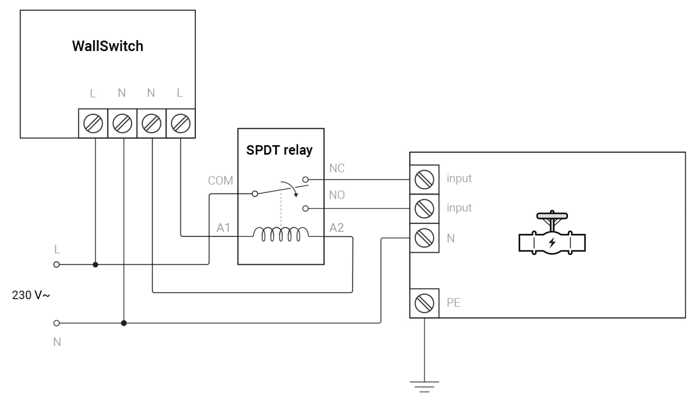
- Connect the power supply source to the power terminals of the WallSwitch observing the polarity.
- Connect the N output terminal (neutral) of WallSwitch to the A2 terminal of the coupling relay, and the L terminal (phase) of WallSwitch — to the A1 contact terminal of the coupling relay.
- Connect the COM contact terminal of the coupling relay to the L contact terminal of the power source.
- Connect the NC contact terminal of the coupling relay to the control opening input of the electric valve, and the NO contact terminal — to the closing input.
- Connect the N contact terminal (neutral) of the electric valve to the N contact terminal of the power source and ground the PE contact of the electric valve.
Such connection ensures the closing of the electromagnetic valve using WallSwitch.
Operation of the 230 V~ electromagnetic valves featuring two control inputs
No additional WallSwitch setup via the app is required.
Click the switch in the WallSwitch line — the state of the relay contacts will change to the opposite.
When WallSwitch contacts are closed, the electric valve is supplied with power and closes. The control input is cut off when contacts are opened, and the electric valve opens.
Automatic operation of an electric valve
Create a scenario to activate one or several electric valves automatically when arming/disarming the security system, by alarm or other conditions. The scenario by the alarm of the leak detector creates the water leak prevention system that shuts off the water without the user.
A scenario can be created in the relay settings:
Devices ![]() → Relay (or WallSwitch) → Settings
→ Relay (or WallSwitch) → Settings ![]() → Scenarios.
→ Scenarios.
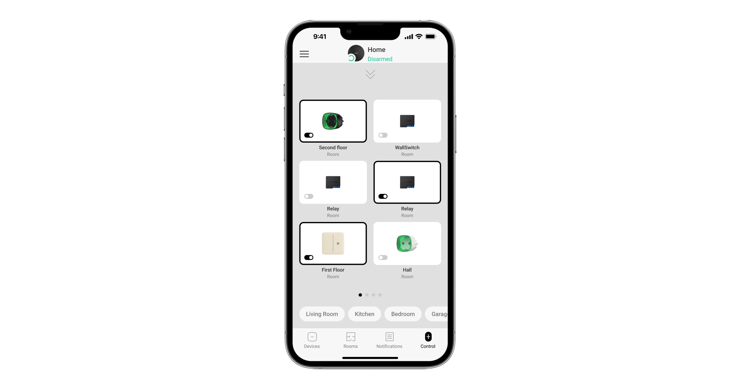
Quick access to automation devices
For quick access to control Relay, WallSwitch, or other automation devices, do the following steps in the Ajax apps:
- Go to the Control tab.
- Swipe up.
- Control the required devices.
- Swipe down to return to the Control tab.